US4991668A - Controlled directional drilling system and method - Google Patents
Controlled directional drilling system and method Download PDFInfo
- Publication number
- US4991668A US4991668A US07/306,050 US30605089A US4991668A US 4991668 A US4991668 A US 4991668A US 30605089 A US30605089 A US 30605089A US 4991668 A US4991668 A US 4991668A
- Authority
- US
- United States
- Prior art keywords
- housing
- motor
- tool
- sub
- bent
- Prior art date
- Legal status (The legal status is an assumption and is not a legal conclusion. Google has not performed a legal analysis and makes no representation as to the accuracy of the status listed.)
- Expired - Fee Related
Links
Images


Classifications
-
- E—FIXED CONSTRUCTIONS
- E21—EARTH DRILLING; MINING
- E21B—EARTH DRILLING, e.g. DEEP DRILLING; OBTAINING OIL, GAS, WATER, SOLUBLE OR MELTABLE MATERIALS OR A SLURRY OF MINERALS FROM WELLS
- E21B47/00—Survey of boreholes or wells
- E21B47/02—Determining slope or direction
- E21B47/024—Determining slope or direction of devices in the borehole
-
- E—FIXED CONSTRUCTIONS
- E21—EARTH DRILLING; MINING
- E21B—EARTH DRILLING, e.g. DEEP DRILLING; OBTAINING OIL, GAS, WATER, SOLUBLE OR MELTABLE MATERIALS OR A SLURRY OF MINERALS FROM WELLS
- E21B47/00—Survey of boreholes or wells
- E21B47/02—Determining slope or direction
- E21B47/022—Determining slope or direction of the borehole, e.g. using geomagnetism
-
- E—FIXED CONSTRUCTIONS
- E21—EARTH DRILLING; MINING
- E21B—EARTH DRILLING, e.g. DEEP DRILLING; OBTAINING OIL, GAS, WATER, SOLUBLE OR MELTABLE MATERIALS OR A SLURRY OF MINERALS FROM WELLS
- E21B7/00—Special methods or apparatus for drilling
- E21B7/04—Directional drilling
- E21B7/06—Deflecting the direction of boreholes
- E21B7/068—Deflecting the direction of boreholes drilled by a down-hole drilling motor
Definitions
- This invention relates to new and useful improvements in controlled drilling systems, and more particularly to a system of apparatus and method for controlled directional drilling utilizing a down hole motor with orienting and circulating tools and apparatus for orienting a bent sub or bent motor housing in relation to the surveying tool in the drill string to control the direction of the hole being drilled.
- Drilling systems wherein a drill bit is operated by a down hole motor, such as positive displacement fluid motors or turbine driven motors are known in the art.
- a down hole motor such as positive displacement fluid motors or turbine driven motors
- the drill bit is rotated by a rotor turned by flow of fluid, such as drilling fluid through the motor assembly.
- These down hole motors and drills are used in many cases for angular drilling of wells by supporting the motor on a bent sub or by using a motor having a bent housing.
- a surveying tool connected in the drill string above the motor senses and controls the direction of drilling.
- it is necessary to locate the bend in the bent sub or the bend in a bent motor housing accurately in relation to the surveying tool to permit accurate control.
- An accurate orientation of the bent sub or bent motor housing in relation to the surveying tool has been difficult with prior art equipment and such difficulties have been largely overcome by this invention.
- Slim hole drilling is less expensive than conventional drilling because it uses smaller tools, rigs, casing, and mud systems.
- "Slim hole drilling” as used herein refers to drilling operations in which the hole size is smaller than usual.
- the slim hole is drilled with less than normal diameter tools, for example, 61/2" bit or less.
- the tight clearances in smaller casing sizes provides some advantages and some disadvantages.
- Buckling of the pipe is controlled by hole diameter, drill pipe and tool joint size, and the required pushing force or negative drag. Increasing the tool joint diameter reduces buckling problems, however adequate clearance is needed inside the hole and casing for circulation and pipe movement. Because the pipe is in compression when pushed into the horizontal hole and in tension when pulled out of the hole, it must be appreciably stiffer than pipe used under normal conditions. Finally, there is the effect of rotation and bending on the tool joints and larger diameter elements of the drill string.
- Tschirky U.S. Pat. No. 3,879,094 discloses a down hole motor consisting of a positive displacement motor having a bearing assembly on the motor housing which has tungsten carbide radial bearings and a plurality of longitudinally spaced axial thrust bearings.
- Tiraspolsky U.S. Pat. No. 3,449,030 discloses a bearing assembly for use in down hole motors which includes a plurality of spaced axial thrust bearings having woven wire annular pads which function to absorb shock.
- Garrison U.S. Pat. No. 3,594,106 discloses a down hole motor assembly with longitudinally spaced axial thrust bearings and a spring mechanism for absorbing shock.
- Maurer et al U.S. Pat. No. 4,114,704 discloses a turbodrill having means to use the pressure of drilling mud to reverse the application of bearing forces from the lower to the upper thrust bearings.
- Another object of this invention to provide a system and method for horizontal slim hole drilling in which all drilling is done with motors and any pipe rotation is incidental to the drilling operation thereby allowing the use of conventional drill pipe.
- Another object of this invention is to provide a system and method for horizontal slim hole drilling in which the bottom hole assembly is of minimum diameter and has no shoulders thus reducing the tendency to hang and allowing constant bit weight to be maintained.
- Another object of this invention is to provide a system and method for horizontal slim hole drilling.
- a further object of this invention is to provide a system and method for horizontal slim hole drilling.
- Another object of this invention is to provide a controlled directional drilling system and method utilizing a drill string having a surveying tool and a drilling motor supported thereon by a bent sub, or in lieu thereof a drilling motor having a bent housing, with means for orienting the bend in the bent sub or bent motor housing accurately in relation to the surveying tool.
- Another object of this invention is to provide a controlled directional drilling system and method comprising a drill string having a surveying tool and a drilling motor supported thereon by a bent sub, or in lieu thereof a drilling motor having a bent housing, with an orienting tool or sub for orienting the bend in the bent sub or bent motor housing accurately in relation to the surveying tool and a bypass tool for use in combination with the motor for earth drilling and to flush cuttings and debris from the well bore.
- Another object of this invention is to provide a controlled directional drilling system and method utilizing a drill string for drilling a deviated well bore into the earth having a fluid operated drilling motor and drill bit secured on the bottom end and supported for angular drilling relative to a substantially vertical well bore, a bypass tool connected to a bent sub, or in lieu thereof a drilling motor having a bent housing, an orienting tool and mule shoe keying sub connected to the bypass tool, and a surveying tool connected in the drill string above the orienting tool and mule shoe sub.
- Still another object of this invention is to provide a controlled directional drilling system and method utilizing a drill string having a bent sub or bent motor housing, a bypass tool, orienting tool and mule shoe sub, and a surveying tool which will orient the bend in the sub or motor housing accurately in relation to the surveying tool and is capable of fine angular adjustment to orient the bend in the sub or motor housing accurately in relation to the surveying tool.
- Still another object of this invention is to provide a controlled directional drilling system and method utilizing a drill string having a bent sub or bent motor housing, a bypass tool, orienting tool and mule shoe sub, and a surveying tool which will orient the bend in the sub or motor housing accurately in relation to the surveying tool and is capable of operation under high pressure conditions.
- Still another object of this invention is to provide a controlled directional drilling system and method utilizing a drill string having a bent sub or bent motor housing, a bypass tool, orienting tool and mule shoe sub, and a surveying tool which will orient the bend in the sub or motor housing accurately in relation to the surveying tool and which includes means to counterbalance the pressures tending to open the bypass tool.
- FIG. 1A is a fragmentary view of the bypass tool of the apparatus shown in FIG. 1 with the tool lifted to a position opening the bypass valve for circulation of fluid to flush the well bore.
- FIG. 3 is a longitudinal cross section of a mule shoe sub used to key the surveying tool to the orienting tool or sub.
- FIG. 4 is a longitudinal cross section of a mule shoe sub of FIG. 3 in place keying the surveying tool to the orienting tool or sub.
- FIG. 5 is a sectional view taken on the line 5--5 of FIG. 2B showing the splined connection for orienting the key for the mule shoe sub to position it accurately in relation to the bend in the bent sub or bent motor housing used for angular drilling.
- FIGS. 7A and 7B taken together constitute a longitudinal sectional view showing details of the bypass tool and its relation to the rotary shaft which carries the drill bit, showing the bypass valve in an opened position.
- FIG. 8 is a sectional view taken on the line 8--8 of FIG. 6B.
- FIG. 1 there is shown a vertical section through a bore hole 1 in the earth, with a casing 2 in place, and a lower portion 3 extending at an angle, illustrating slant or angular drilling.
- the equipment described herein is primarily useful in slim hole drilling systems but can be used with larger diameter systems as well.
- Drilling motor 5 is a fluid operated motor with a drill bit 6 operated thereby.
- Motor 5 may be a positive displacement motor, e.g. a Moineau motor, or a turbodrill.
- the string of drill pipe 4 conducts drilling fluid through the motor assembly and into the bore hole.
- Motor 5 is supported by a bent sub 7 at a substantial angle to the vertical portion of well bore 1 and has bent housing 5b and a deflection pad 5a for continuing the drilling of the well bore portion 3 at an angle to the vertical portion thereof.
- the motor 5 is shown in combination with a bent sub.
- Deflection pad 5a acts as a fulcrum and increases the side load on the drill bit, causing it to drill along a sharper curve.
- bypass tool or sub 8 is connected to the top end of the bent sub or bent housing of the motor in the flow of drilling fluid which operates motor 5 and is operated as desired to direct flow of drilling fluid into the well bore 1 to flush out cuttings and debris which interferes with the drilling operation.
- Bypass tool or sub 8 is shown in FIGS. 1, 6A and 6B in a telescoped position and in FIGS. 1A, 7A and 7B in an extended or operated position.
- Bypass sub 8 is an optional feature and may or may not be used according to the conditions encountered in drilling.
- a circulating and orienting sub 9 is connected at one end to bypass tool or sub 8 and to a surveying tool 10 at the other end.
- the circulating and orienting sub 9 includes means to adjust the angular orientation of the point of connection to bypass tool or sub 8 in relation to the connection to bent sub 7 or bent motor housing 5.
- the surveying tool 10 is connected in drill string 4 above the circulating and orienting sub 9, bypass tool or sub 8, and motor 5 for determining and controlling the direction of drilling.
- a mule shoe keying sub 11 is connected to the surveying tool 10 for connecting and orienting the position of the motor 5 in relation to the surveying tool. Details of construction of mule shoe keying sub 11 and circulating and orienting sub or tool 9 are shown in FIGS. 2A, 2B, and 3-5 of the drawings.
- Circulating and orienting sub or tool 9 (see FIG. 5) comprises a lower tubular housing portion 12 and an upper housing or connecting sub 13 (FIGS. 2A and 2B).
- Connecting sub 13 has female threads 14 at its upper end and male threads 15 and an open bore 16 extending longitudinally.
- Lower housing portion 12 has female threads 17 at its upper end and male threads 18 at its lower end.
- a longitudinal passageway 19 extends the entire length of lower housing portion 12.
- An orienting, receiving sleeve 20 is fitted in the upper end of lower housing portion 12 and has an orienting key 21 supported in an opening 22 in the side wall thereof. Key 21 extends radially inward of passageway 19 and cooperates with the mule shoe as described below.
- the upper end of lower housing portion 12 has a plurality of longitudinal splines 23 and grooves 24 which are equal in size and equally spaced around the wall of the housing.
- Sleeve 20 has a plurality of longitudinal splines 25 and grooves 26 which are equal in size and equally spaced therearound and fit the grooves 24 and splines 23 of housing portion 12. This system of grooves and splines permits installation of sleeve 20 in housing portion 12 with incremental adjustment of the angular orientation by amounts corresponding to the spacing of the grooves and splines in the connection.
- the upper end of sleeve 20 has a peripheral groove 27 sealed by O-ring 28.
- the lower end of lower housing portion 12 has a plurality of side openings 28a.
- a seal sleeve 29 is positioned in closing relation to openings and has upper and lower grooves 30 and 31 sealed by O-rings 32 and 33, respectively.
- the upper end of seal sleeve 29 is keyed by shear pin 34 to retainer ring 35.
- An annular, elongated float valve 36 (a modified Baker float valve) is positioned between the upper surface of retainer ring 35 and the bottom end of orienting sleeve 20.
- Baker float 36 is open longitudinally and forms part of the passageway extending the entire length of the orienting sub or tool 11.
- Float valve 36 has a flapper check valve 36a, spring loaded closed, about half way along its length.
- the side opening 36b in float valve 36 is closed by a metal cover 36c tack welded in place.
- Mule shoe keying sub 11 is shown in FIG. 3 and its connection to orienting sub 9 is shown in FIG. 4.
- Mule shoe keying sub 11 comprises a tubular housing 37 which is internally threaded as at 38 for connection to the surveying tool 10.
- Tubular housing 37 has a plurality of longitudinal slots 39 and 40 and is cut away as shown at 41 to a guide tip portion 42.
- a spring-loaded latch member 43 is pivotally supported on the end 44 of latch support member 45 secured by machine screws 46 to the wall of tubular housing 37.
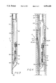
- the bypass tool or sub 8 comprises an outer tubular housing 47 (also called a drive sub) with an inner tubular housing 48 (also called an orifice shaft) telescoped inside for longitudinal sliding movement therein and having a telescoped position and an extended position.
- Outer tubular housing 47 is formed of two sections 49 and 50 which are threadedly secured together as described below.
- Tubular housing or drive sub 47 has an enlarged bore 51 in the upper portion and a smaller bore 52 in the lower section with a tapered transition surface 53 therebetween.
- Tubular housing or orifice shaft 48 has a larger outside diameter portion 54 at its upper end and a smaller outside diameter portion 55 at its lower end with a tapered transition surface 56 therebetween.
- Tubular housing or orifice shaft 48 is positioned for longitudinal sliding movement in tubular housing or drive sub 47 with larger O.D. portion 54 sliding in enlarged bore 51 and smaller O.D. portion 55 sliding in smaller bore 52.
- the smaller O.D. portion 55 which slides in smaller bore 52 functions as a sliding plug valve for opening and closing the bypass as will be described more fully below.
- tubular housing 48 The upper end of tubular housing 48 is enlarged as indicated at 57 forming a threaded box 58 for connection to the orienting sub 9.
- the lower end of tubular housing 47 terminates in a threaded pin portion 59 for connection to the upper end of the bent sub 7 or motor 5.
- the mid-section 60 (FIG. 6B) of the housings 47 and 48 is configured in a noncircular, e.g., polygonal or splined, cross section 47a and 48a (FIG. 8) which permits longitudinal sliding movement of the housings while restraining them from relative rotary movement. This construction allows rotary movement to be transferred from the drill string 4 and orienting sub 9 to down hole motor 5.
- the bore 61, extending the entire length of tubular housing or drive sub 48 and the smaller I.D. bore 52 in the lower end of tubular housing or orifice shaft 47 form a continuous passage for conducting drilling fluid from the surface from drill string 4 and orienting sub 9 to down hole motor 5.
- the outer lower wall portion of tubular housing 47 has one or more apertures or openings 62 extending from the smaller I.D. bore 52 to the outer surface of the tool for discharge of drilling fluid therethrough when the tool is extended to an operated position.
- a cylindrical screen 63 surrounds and is secured to housing section 16 to prevent debris or cuttings from the bore hole from entering the bypass tool.
- the outer tubular housing or drive sub 47 comprises two separate sections with male threads 64 on upper section 49 and female threads 65 on lower section 50.
- the male and female threads 64 and 65 are threaded together with the end of the male threaded portion defining a stop shoulder 66 in the enlarged bore portion 51 of threaded housing section 50.
- the enlarged bore portion of the upper end of drive sub 47 has a cylindrical bearing 67 of a suitable bearing metal or a hard rubber.
- Bearing 67 is secured in place by set screws 68 and is sealed by O-rings 69 and 70.
- a wiper ring retainer 71 is secured in place against the end of bearing 67 by snap ring 72 and retains a wiper ring 73.
- the lower end of the enlarged O.D. portion of orifice shaft 48 is threaded at 74 and has a retaining nut 75 threadedly secured thereon.
- Retaining nut 75 has a smooth cylindrical external surface with (Parker) Molygard wear rings 76 for wear protection and O-ring 77 to seal against the bore of drive sub lower section 50.
- the lower end 78 of retaining nut 75 abuts a shoulder 79 in drive sub lower section 50 and limits the extent of telescoping movement of the tool housings.
- a hole or aperture 80 opens through the wall of orifice shaft 48 into the space above retaining nut 75 and intersects a groove 81 for applying pressure into the region from above retaining nut 75 to the lower end of bearing 67.
- the lower, small O.D., end 55 of orifice shaft 48 extends through the smaller bore 52 in drive sub lower section 50 and is sealed peripherally by O-rings 82 to function as a sliding plug valve. Longitudinal movement of orifice shaft 48 in drive sub 47 will move the lower end 55 and O-rings 82 past the side openings 62 in drive sub 47 opening the normally closed valve to permit drilling fluid to exhaust from the bypass tool ahead of down hole motor 5 to flush the well bore of cuttings and debris.
- a 60 to 80 foot section is milled out of the casing starting 30 feet above the kickoff point, and a cement plug is placed in the milled out section.
- the cement is dressed down to the kickoff point.
- the 30 foot section above it gives adequate room to orient the bottom hole assembly (BHA) using the steering tool magnetics.
- BHA bottom hole assembly
- the hole is kicked off about 20 feet.
- the pipe is then tripped and the side-cutting drill bit and turn assembly are run back into the hole. It should be understood that it would also be possible to exit the hole via a conventional whipstock and milled window.
- the "turning" drilling assembly drills a fixed curve that is a function of the tool face orientation and, to a lesser degree, the formation. As the bit drills along the curve, it may be necessary to modify the assembly to keep the turn on track. During the drilling of the curve, the hole is closely monitored with a steering tool and short interval calculations to avoid changes in the inclination or azimuth. When the bottom hole assembly (BHA) reaches horizontal, a straight hole assembly is installed.
- BHA bottom hole assembly
- the present slim hole drilling system is flexible and easy to steer.
- the tool face can be turned easily and the change in drilling direction is rapid because of the limber system.
- the bit will drift off course if not continuously monitored.
- single shot surveys are not adequate.
- a preferred drilling technique is to drill depleted formations with an underbalanced fluid column. Low mud weights require careful attention to hole conditions, but there is a significant payoff in higher drilling rates and reduced lost circulation problems, as well as protecting the formation.
- This apparatus is assembled and operated by assembling the motor 5, bent sub 7, bypass tool or sub 8, and orienting sub or tool 9 on the drill pipe 4.
- bypass sub or tool 8 may be installed directly to the housing of the bent motor 5 or straight motor if the bent sub 7 is not used.
- Orienting sleeve 20 is adjusted angularly, as shown in FIG. 5, to position key 21 in alignment with the bend in bent sub 7, or alternatively, the bend in bent motor housing 5.
- mule shoe sub 11 is first installed on the lower end of surveying tool 10 and then slid into the upper end of the orienting sub 9.
- the lower portion of slot 40 and the guide portion 41 and 42 engages key 21 and guides the connection until the end of slot 40 engages the upper end of key 21 and latch 43 snaps into latching position as seen in FIG. 4.
- the bend in bent sub 7 or in bent motor housing 5 is properly aligned with surveying tool 10 so that it can control the drilling in the direction of the bend.
- Drilling mud (or other drilling fluid) is pumped through the drill pipe 4, the orienting sub or tool 10, the bypass tool 8 and through the motor 5 and out through the drill bit 6.
- the flow of the drilling mud (or other drilling fluid) through the motor 5 causes it to rotate at high speed to turn the drill bit 6 for drilling the hole.
- the apparatus has been described with a Moineau type positive displacement motor although other fluid-operated motors, such as turbines and the like, may be used.
- the Baker float valve 36 with flapper valve 36a protects the equipment against backflow of drilling fluid or formation fluids.
- the sleeve valve 29 normally closes the bypass ports 28.
- a ball 50 (shown in dotted line) is dropped into the drill string.
- Ball 50 is of a size permitting it to pass through the drill string and orienting sub 9 to close against the seat of the sleeve valve 29.
- the application of fluid pressure against the ball 50 will shear the pin 34 and move sleeve valve 29 downward to open valve ports 28 and allow drilling fluid to flow out from the drill string.
- O-ring seals 82 close off the bypass openings or ports 62. With the tool in the closed position, all of the drilling fluid passes through the down hole drilling motor 5.
- the tool When the orifice shaft 48 is lifted, the tool extends, allowing the seals 82 to move upward past the bypass openings or ports 62 and allowing drilling fluid to flow directly into the well bore annulus and bypass the down hole drilling motor 5.
- the screen 63 covering the bypass ports 62 prevents drill cuttings or other debris from entering the tool and plugging the motor 5 or drill bit 6.
- the hydraulic opening force tending to open the unbalanced tool can be large. In a 4-inch diameter tool the opening force is nearly 8,000 lbs. In such a case, the weight required to close the tool would be the opening force plus the bit weight plus the motor weight. This high bit weight may cause the bit torque to exceed the motor output torque and stall the motor. For this reason, the balanced design described above is preferred.
- the tool is designed so that the upward directed force (F opening ) tending to open the tool is:
- the net force tends to open the tool when F net is greater than 0 and close the tool when F net is smaller than 0.
- the total bit weight (F bit ) required to close the tool equals:
- the net force can be adjusted, by proper design, to compensate exactly for the weight of the bit and motor.
- the tool will close when thrust is first applied to the drill bit and it will open when the drill string is raised to lift the orifice sub in the tool.
- the tool is designed with some small net force tendency to open since there are always frictional forces to be overcome.
- the tool shown and described above is substantially balanced. However, if an unbalanced design is desired, it is produced by plugging the opening 80 and eliminating seals 77 on the retaining nut 75.
Abstract
Description
F.sub.H =πD.sub.1.sup.2 P/4 (lbs.)
P=P.sub.I -P.sub.A
P=P.sub.motor +P.sub.bit
F.sub.opening =πD.sub.1.sup.2 P/4
F.sub.closing =π(D.sub.2.sup.2 -D.sub.3.sup.2)P/4
F.sub.net =F.sub.opening -F.sub.closing
F.sub.net =π(D.sub.2.sup.2 +D.sub.3.sup.2)P/4
F.sub.bit =F.sub.net +W.sub.B +W.sub.M
Claims (38)
Priority Applications (1)
| Application Number | Priority Date | Filing Date | Title |
|---|---|---|---|
| US07/306,050 US4991668A (en) | 1989-02-06 | 1989-02-06 | Controlled directional drilling system and method |
Applications Claiming Priority (1)
| Application Number | Priority Date | Filing Date | Title |
|---|---|---|---|
| US07/306,050 US4991668A (en) | 1989-02-06 | 1989-02-06 | Controlled directional drilling system and method |
Publications (1)
| Publication Number | Publication Date |
|---|---|
| US4991668A true US4991668A (en) | 1991-02-12 |
Family
ID=23183538
Family Applications (1)
| Application Number | Title | Priority Date | Filing Date |
|---|---|---|---|
| US07/306,050 Expired - Fee Related US4991668A (en) | 1989-02-06 | 1989-02-06 | Controlled directional drilling system and method |
Country Status (1)
| Country | Link |
|---|---|
| US (1) | US4991668A (en) |
Cited By (48)
| Publication number | Priority date | Publication date | Assignee | Title |
|---|---|---|---|---|
| US5135059A (en) * | 1990-11-19 | 1992-08-04 | Teleco Oilfield Services, Inc. | Borehole drilling motor with flexible shaft coupling |
| US5269632A (en) * | 1992-10-22 | 1993-12-14 | Shell Oil Company | Method for strengthening the structural base of offshore structures |
| US5275511A (en) * | 1992-10-22 | 1994-01-04 | Shell Oil Company | Method for installation of piles in offshore locations |
| US5277519A (en) * | 1992-10-22 | 1994-01-11 | Shell Oil Company | Well drilling cuttings disposal |
| US5284513A (en) * | 1992-10-22 | 1994-02-08 | Shell Oil Co | Cement slurry and cement compositions |
| US5285679A (en) * | 1992-10-22 | 1994-02-15 | Shell Oil Company | Quantification of blast furnace slag in a slurry |
| US5301754A (en) * | 1992-10-22 | 1994-04-12 | Shell Oil Company | Wellbore cementing with ionomer-blast furnace slag system |
| US5301752A (en) * | 1992-10-22 | 1994-04-12 | Shell Oil Company | Drilling and cementing with phosphate-blast furnace slag |
| US5307876A (en) * | 1992-10-22 | 1994-05-03 | Shell Oil Company | Method to cement a wellbore in the presence of carbon dioxide |
| US5307877A (en) * | 1992-10-22 | 1994-05-03 | Shell Oil Company | Wellbore sealing with two-component ionomeric system |
| US5309999A (en) * | 1992-10-22 | 1994-05-10 | Shell Oil Company | Cement slurry composition and method to cement wellbore casings in salt formations |
| US5309997A (en) * | 1992-10-22 | 1994-05-10 | Shell Oil Company | Well fluid for in-situ borehole repair |
| US5311945A (en) * | 1992-10-22 | 1994-05-17 | Shell Oil Company | Drilling and cementing with phosphate |
| US5311944A (en) * | 1992-10-22 | 1994-05-17 | Shell Oil Company | Blast furnace slag blend in cement |
| US5314022A (en) * | 1992-10-22 | 1994-05-24 | Shell Oil Company | Dilution of drilling fluid in forming cement slurries |
| US5314031A (en) * | 1992-10-22 | 1994-05-24 | Shell Oil Company | Directional drilling plug |
| US5322124A (en) * | 1992-10-22 | 1994-06-21 | Shell Oil Company | Squeeze cementing |
| US5325922A (en) * | 1992-10-22 | 1994-07-05 | Shell Oil Company | Restoring lost circulation |
| US5332040A (en) * | 1992-10-22 | 1994-07-26 | Shell Oil Company | Process to cement a casing in a wellbore |
| US5343951A (en) * | 1992-10-22 | 1994-09-06 | Shell Oil Company | Drilling and cementing slim hole wells |
| US5343952A (en) * | 1992-10-22 | 1994-09-06 | Shell Oil Company | Cement plug for well abandonment |
| US5343950A (en) * | 1992-10-22 | 1994-09-06 | Shell Oil Company | Drilling and cementing extended reach boreholes |
| US5343947A (en) * | 1992-10-22 | 1994-09-06 | Shell Oil Company | Anchor plug for open hole test tools |
| US5351759A (en) * | 1992-10-22 | 1994-10-04 | Shell Oil Company | Slag-cement displacement by direct fluid contact |
| US5358049A (en) * | 1992-10-22 | 1994-10-25 | Shell Oil Company | Conversion of emulsion mud to cement |
| US5379843A (en) * | 1992-10-22 | 1995-01-10 | Shell Oil Company | Side-tracking cement plug |
| US5394951A (en) * | 1993-12-13 | 1995-03-07 | Camco International Inc. | Bottom hole drilling assembly |
| US5445230A (en) * | 1993-10-01 | 1995-08-29 | Wattenburg; Willard H. | Downhole drilling subassembly and method for same |
| US5673765A (en) * | 1993-10-01 | 1997-10-07 | Wattenburg; Willard H. | Downhole drilling subassembly and method for same |
| WO1998037300A1 (en) * | 1997-02-20 | 1998-08-27 | Bj Services Company, U.S.A. | Bottomhole assembly and methods of use |
| US5857531A (en) * | 1997-04-10 | 1999-01-12 | Halliburton Energy Services, Inc. | Bottom hole assembly for directional drilling |
| US6073707A (en) * | 1998-03-11 | 2000-06-13 | Canadian Downhole Drill Systems Inc. | Downhole sub with kick pad for directional drilling |
| WO2000052294A3 (en) * | 1999-03-03 | 2001-04-12 | Earth Tool Co Llc | Drill head for directional boring |
| US6622798B1 (en) * | 2002-05-08 | 2003-09-23 | Halliburton Energy Services, Inc. | Method and apparatus for maintaining a fluid column in a wellbore annulus |
| US20060006004A1 (en) * | 2004-07-09 | 2006-01-12 | Jim Terry | Method for extracting coal bed methane with source fluid injection |
| GB2428261A (en) * | 2003-04-02 | 2007-01-24 | Halliburton Energy Serv Inc | Method and apparatus for increasing drilling capacity and removing cuttings when drilling with coiled tubing |
| USRE39970E1 (en) | 2000-07-19 | 2008-01-01 | Schlumberger Technology Corporation | Downhole adjustable bent housing for directional drilling |
| WO2013023020A1 (en) * | 2011-08-10 | 2013-02-14 | Gas Technology Institute | Telescopic laser purge nozzle |
| WO2013165612A1 (en) * | 2012-05-04 | 2013-11-07 | Kolle Jack J | Steerable gas turbodrill |
| CN103643918A (en) * | 2013-12-20 | 2014-03-19 | 北京大地高科煤层气工程技术研究院 | Method for searching for and preventing mine water seepage of Ordovician limestone mine field |
| US9890593B2 (en) | 2015-07-02 | 2018-02-13 | Bitswave Inc. | Steerable earth boring assembly having flow tube with static seal |
| US9890592B2 (en) | 2015-07-02 | 2018-02-13 | Bitswave Inc. | Drive shaft for steerable earth boring assembly |
| CN107893635A (en) * | 2017-11-27 | 2018-04-10 | 中石化石油机械股份有限公司研究院 | Controllable type waterpower pulse drilling speed instrument |
| US9970237B2 (en) | 2015-07-02 | 2018-05-15 | Bitswave Inc. | Steerable earth boring assembly |
| CN110374581A (en) * | 2018-04-13 | 2019-10-25 | 中国石油化工股份有限公司 | Superhigh temperature mechanical orienting tool gauge and its design method |
| US10781639B1 (en) | 2019-03-27 | 2020-09-22 | Saudi Arabian Oil Company | Self-adjusting downhole motor |
| USD918870S1 (en) * | 2019-08-09 | 2021-05-11 | SDS Asia Limited, BVI # 1748971 | Speaker |
| US11319756B2 (en) | 2020-08-19 | 2022-05-03 | Saudi Arabian Oil Company | Hybrid reamer and stabilizer |
Citations (4)
| Publication number | Priority date | Publication date | Assignee | Title |
|---|---|---|---|---|
| US3717208A (en) * | 1971-08-05 | 1973-02-20 | E Anderson | Seal and equalizing arrangement for a directional drilling apparatus |
| US4067404A (en) * | 1976-05-04 | 1978-01-10 | Smith International, Inc. | Angle adjustment sub |
| US4667751A (en) * | 1985-10-11 | 1987-05-26 | Smith International, Inc. | System and method for controlled directional drilling |
| US4817740A (en) * | 1987-08-07 | 1989-04-04 | Baker Hughes Incorporated | Apparatus for directional drilling of subterranean wells |
-
1989
- 1989-02-06 US US07/306,050 patent/US4991668A/en not_active Expired - Fee Related
Patent Citations (4)
| Publication number | Priority date | Publication date | Assignee | Title |
|---|---|---|---|---|
| US3717208A (en) * | 1971-08-05 | 1973-02-20 | E Anderson | Seal and equalizing arrangement for a directional drilling apparatus |
| US4067404A (en) * | 1976-05-04 | 1978-01-10 | Smith International, Inc. | Angle adjustment sub |
| US4667751A (en) * | 1985-10-11 | 1987-05-26 | Smith International, Inc. | System and method for controlled directional drilling |
| US4817740A (en) * | 1987-08-07 | 1989-04-04 | Baker Hughes Incorporated | Apparatus for directional drilling of subterranean wells |
Cited By (57)
| Publication number | Priority date | Publication date | Assignee | Title |
|---|---|---|---|---|
| US5135059A (en) * | 1990-11-19 | 1992-08-04 | Teleco Oilfield Services, Inc. | Borehole drilling motor with flexible shaft coupling |
| US5269632A (en) * | 1992-10-22 | 1993-12-14 | Shell Oil Company | Method for strengthening the structural base of offshore structures |
| US5275511A (en) * | 1992-10-22 | 1994-01-04 | Shell Oil Company | Method for installation of piles in offshore locations |
| US5277519A (en) * | 1992-10-22 | 1994-01-11 | Shell Oil Company | Well drilling cuttings disposal |
| US5284513A (en) * | 1992-10-22 | 1994-02-08 | Shell Oil Co | Cement slurry and cement compositions |
| US5285679A (en) * | 1992-10-22 | 1994-02-15 | Shell Oil Company | Quantification of blast furnace slag in a slurry |
| US5301754A (en) * | 1992-10-22 | 1994-04-12 | Shell Oil Company | Wellbore cementing with ionomer-blast furnace slag system |
| US5301752A (en) * | 1992-10-22 | 1994-04-12 | Shell Oil Company | Drilling and cementing with phosphate-blast furnace slag |
| US5307876A (en) * | 1992-10-22 | 1994-05-03 | Shell Oil Company | Method to cement a wellbore in the presence of carbon dioxide |
| US5307877A (en) * | 1992-10-22 | 1994-05-03 | Shell Oil Company | Wellbore sealing with two-component ionomeric system |
| US5309999A (en) * | 1992-10-22 | 1994-05-10 | Shell Oil Company | Cement slurry composition and method to cement wellbore casings in salt formations |
| US5309997A (en) * | 1992-10-22 | 1994-05-10 | Shell Oil Company | Well fluid for in-situ borehole repair |
| US5311945A (en) * | 1992-10-22 | 1994-05-17 | Shell Oil Company | Drilling and cementing with phosphate |
| US5311944A (en) * | 1992-10-22 | 1994-05-17 | Shell Oil Company | Blast furnace slag blend in cement |
| US5314022A (en) * | 1992-10-22 | 1994-05-24 | Shell Oil Company | Dilution of drilling fluid in forming cement slurries |
| US5314031A (en) * | 1992-10-22 | 1994-05-24 | Shell Oil Company | Directional drilling plug |
| US5322124A (en) * | 1992-10-22 | 1994-06-21 | Shell Oil Company | Squeeze cementing |
| US5325922A (en) * | 1992-10-22 | 1994-07-05 | Shell Oil Company | Restoring lost circulation |
| US5332040A (en) * | 1992-10-22 | 1994-07-26 | Shell Oil Company | Process to cement a casing in a wellbore |
| US5343951A (en) * | 1992-10-22 | 1994-09-06 | Shell Oil Company | Drilling and cementing slim hole wells |
| US5343952A (en) * | 1992-10-22 | 1994-09-06 | Shell Oil Company | Cement plug for well abandonment |
| US5343950A (en) * | 1992-10-22 | 1994-09-06 | Shell Oil Company | Drilling and cementing extended reach boreholes |
| US5343947A (en) * | 1992-10-22 | 1994-09-06 | Shell Oil Company | Anchor plug for open hole test tools |
| US5351759A (en) * | 1992-10-22 | 1994-10-04 | Shell Oil Company | Slag-cement displacement by direct fluid contact |
| US5358049A (en) * | 1992-10-22 | 1994-10-25 | Shell Oil Company | Conversion of emulsion mud to cement |
| US5379843A (en) * | 1992-10-22 | 1995-01-10 | Shell Oil Company | Side-tracking cement plug |
| US5673765A (en) * | 1993-10-01 | 1997-10-07 | Wattenburg; Willard H. | Downhole drilling subassembly and method for same |
| US5445230A (en) * | 1993-10-01 | 1995-08-29 | Wattenburg; Willard H. | Downhole drilling subassembly and method for same |
| FR2713697A1 (en) * | 1993-12-13 | 1995-06-16 | Camco Int | Downhole drilling assembly. |
| US5394951A (en) * | 1993-12-13 | 1995-03-07 | Camco International Inc. | Bottom hole drilling assembly |
| WO1998037300A1 (en) * | 1997-02-20 | 1998-08-27 | Bj Services Company, U.S.A. | Bottomhole assembly and methods of use |
| GB2338735A (en) * | 1997-02-20 | 1999-12-29 | Bj Services Company Usa | Bottomhole assembly and methods of use |
| GB2338735B (en) * | 1997-02-20 | 2001-08-29 | Bj Services Company Usa | Bottomhole assembly and methods of use |
| US5857531A (en) * | 1997-04-10 | 1999-01-12 | Halliburton Energy Services, Inc. | Bottom hole assembly for directional drilling |
| US6073707A (en) * | 1998-03-11 | 2000-06-13 | Canadian Downhole Drill Systems Inc. | Downhole sub with kick pad for directional drilling |
| WO2000052294A3 (en) * | 1999-03-03 | 2001-04-12 | Earth Tool Co Llc | Drill head for directional boring |
| USRE39970E1 (en) | 2000-07-19 | 2008-01-01 | Schlumberger Technology Corporation | Downhole adjustable bent housing for directional drilling |
| US6622798B1 (en) * | 2002-05-08 | 2003-09-23 | Halliburton Energy Services, Inc. | Method and apparatus for maintaining a fluid column in a wellbore annulus |
| GB2428261A (en) * | 2003-04-02 | 2007-01-24 | Halliburton Energy Serv Inc | Method and apparatus for increasing drilling capacity and removing cuttings when drilling with coiled tubing |
| GB2428261B (en) * | 2003-04-02 | 2007-12-19 | Halliburton Energy Serv Inc | Method and apparatus for increasing drilling capacity and removing cuttings when drilling with coiled tubing |
| US20060006004A1 (en) * | 2004-07-09 | 2006-01-12 | Jim Terry | Method for extracting coal bed methane with source fluid injection |
| US7278497B2 (en) * | 2004-07-09 | 2007-10-09 | Weatherford/Lamb | Method for extracting coal bed methane with source fluid injection |
| WO2013023020A1 (en) * | 2011-08-10 | 2013-02-14 | Gas Technology Institute | Telescopic laser purge nozzle |
| WO2013165612A1 (en) * | 2012-05-04 | 2013-11-07 | Kolle Jack J | Steerable gas turbodrill |
| CN103643918A (en) * | 2013-12-20 | 2014-03-19 | 北京大地高科煤层气工程技术研究院 | Method for searching for and preventing mine water seepage of Ordovician limestone mine field |
| CN103643918B (en) * | 2013-12-20 | 2016-01-20 | 北京大地高科煤层气工程技术研究院 | A kind of searching for Ordovician limestone mining area and the method preventing mine from seeping water |
| US9890592B2 (en) | 2015-07-02 | 2018-02-13 | Bitswave Inc. | Drive shaft for steerable earth boring assembly |
| US9890593B2 (en) | 2015-07-02 | 2018-02-13 | Bitswave Inc. | Steerable earth boring assembly having flow tube with static seal |
| US9970237B2 (en) | 2015-07-02 | 2018-05-15 | Bitswave Inc. | Steerable earth boring assembly |
| CN107893635A (en) * | 2017-11-27 | 2018-04-10 | 中石化石油机械股份有限公司研究院 | Controllable type waterpower pulse drilling speed instrument |
| CN107893635B (en) * | 2017-11-27 | 2023-08-15 | 中石化石油机械股份有限公司研究院 | Controllable hydraulic pulse drilling speed-increasing tool |
| CN110374581A (en) * | 2018-04-13 | 2019-10-25 | 中国石油化工股份有限公司 | Superhigh temperature mechanical orienting tool gauge and its design method |
| US10781639B1 (en) | 2019-03-27 | 2020-09-22 | Saudi Arabian Oil Company | Self-adjusting downhole motor |
| WO2020198303A1 (en) * | 2019-03-27 | 2020-10-01 | Saudi Arabian Oil Company | Self-adjusting downhole motor |
| US10934782B2 (en) | 2019-03-27 | 2021-03-02 | Saudi Arabian Oil Company | Self-adjusting downhole motor |
| USD918870S1 (en) * | 2019-08-09 | 2021-05-11 | SDS Asia Limited, BVI # 1748971 | Speaker |
| US11319756B2 (en) | 2020-08-19 | 2022-05-03 | Saudi Arabian Oil Company | Hybrid reamer and stabilizer |
Similar Documents
| Publication | Publication Date | Title |
|---|---|---|
| US4991668A (en) | Controlled directional drilling system and method | |
| US7004263B2 (en) | Directional casing drilling | |
| US5181576A (en) | Downhole adjustable stabilizer | |
| US6216802B1 (en) | Gravity oriented directional drilling apparatus and method | |
| US7234544B2 (en) | Drill tool shaft-to-housing locking device | |
| US4185704A (en) | Directional drilling apparatus | |
| US7028789B2 (en) | Drilling assembly with a steering device for coiled-tubing operations | |
| US5458208A (en) | Directional drilling using a rotating slide sub | |
| US8708066B2 (en) | Dual BHA drilling system | |
| US20140174831A1 (en) | Directional Drilling Control Using a Bendable Driveshaft | |
| US9163457B2 (en) | Pressure compensation system for an oil-sealed mud motor bearing assembly | |
| GB2438718A (en) | A steerable well drilling system | |
| CA2445085C (en) | Method of drilling an ultra-short radius borehole | |
| US4789032A (en) | Orienting and circulating sub | |
| US4844180A (en) | Downhole drilling motor | |
| RU2114273C1 (en) | Method and device for drilling slant-directed bore-holes | |
| US20050034895A1 (en) | Smart clutch | |
| US11293230B2 (en) | Rotary steerable tool with independent actuators | |
| WO2013165612A1 (en) | Steerable gas turbodrill | |
| US20050133268A1 (en) | Method and apparatus for casing and directional drilling using bi-centered bit | |
| US7311157B1 (en) | Tool for controlling rotation of a bottom hole assembly with respect to a drillstring | |
| US4641717A (en) | Connector housing | |
| RU2405099C2 (en) | Drilling device and borehole sinking method | |
| US11655678B2 (en) | Mud motor bearing assembly for use with a drilling system | |
| SU1716068A1 (en) | Borehole deflector |
Legal Events
| Date | Code | Title | Description |
|---|---|---|---|
| AS | Assignment |
Owner name: MAURER ENGINEERING INC., TEXAS Free format text: ASSIGNMENT OF 1/2 OF ASSIGNORS INTEREST;ASSIGNORS:REHM, WILLIAM A.;MC DONALD, WILLIAM J.;MAURER, WILLIAM C.;AND OTHERS;REEL/FRAME:005039/0616 Effective date: 19890111 Owner name: BECHTEL INVESTMENTS, INC., NEVADA Free format text: ASSIGNMENT OF 1/2 OF ASSIGNORS INTEREST;ASSIGNORS:MC DONALD, WILLIAM J.;MAURER, WILLIAM C.;LEITKO, CURTIS E. JR.;AND OTHERS;REEL/FRAME:005039/0614 Effective date: 19890111 |
|
| FEPP | Fee payment procedure |
Free format text: PAYOR NUMBER ASSIGNED (ORIGINAL EVENT CODE: ASPN); ENTITY STATUS OF PATENT OWNER: LARGE ENTITY |
|
| FPAY | Fee payment |
Year of fee payment: 4 |
|
| FEPP | Fee payment procedure |
Free format text: PAYER NUMBER DE-ASSIGNED (ORIGINAL EVENT CODE: RMPN); ENTITY STATUS OF PATENT OWNER: LARGE ENTITY Free format text: PAYOR NUMBER ASSIGNED (ORIGINAL EVENT CODE: ASPN); ENTITY STATUS OF PATENT OWNER: LARGE ENTITY |
|
| AS | Assignment |
Owner name: BECFIELD DRILLING SERVICES, TEXAS Free format text: ASSIGNMENT OF ASSIGNORS INTEREST;ASSIGNOR:FREMONT GROUP, INC.;REEL/FRAME:007577/0448 Effective date: 19950720 |
|
| AS | Assignment |
Owner name: GENERAL ELECTRIC CAPITAL CORPORATION, A NEW YORK C Free format text: SECURITY AGREEMENT;ASSIGNOR:PHOENIX DRILLING SERVICES, INC., A DELAWARE CORPORATION;REEL/FRAME:008811/0883 Effective date: 19971106 |
|
| AS | Assignment |
Owner name: PHOENIX DRILLING SERVICES, INC., A CORP. OF DE, TE Free format text: ASSET PURCHASE;ASSIGNOR:BECFIELD DRILLING SERVICES;REEL/FRAME:009005/0710 Effective date: 19951128 |
|
| AS | Assignment |
Owner name: PHOENIX DRILLING SERVICES, INC., TEXAS Free format text: TERMINATION OF SECURITY INTEREST IN PATENTS;ASSIGNOR:GENERAL ELECTRIC CAPITAL CORPORATION;REEL/FRAME:009052/0022 Effective date: 19980316 |
|
| AS | Assignment |
Owner name: BLACK WARRIOR WIRELINE CORP., MISSISSIPPI Free format text: ASSIGNMENT OF ASSIGNORS INTEREST;ASSIGNOR:PHOENIX DRILLING SERVICES, INC.;REEL/FRAME:010078/0656 Effective date: 19980316 |
|
| REMI | Maintenance fee reminder mailed | ||
| LAPS | Lapse for failure to pay maintenance fees | ||
| AS | Assignment |
Owner name: FLEET CAPITAL CORPORATION, TEXAS Free format text: SECURITY INTEREST;ASSIGNOR:BLACK WARRIOR WIRELINE CORP.;REEL/FRAME:009781/0784 Effective date: 19980316 |
|
| FP | Lapsed due to failure to pay maintenance fee |
Effective date: 19990212 |
|
| AS | Assignment |
Owner name: PHOENIX DRILLING SERVICES, INC., TEXAS Free format text: ASSIGNMENT OF ASSIGNORS INTEREST;ASSIGNOR:PHOENIX ENERGY ACQUISITION CORPOPRATION II;REEL/FRAME:009987/0761 Effective date: 19951228 Owner name: PHOENIX ENERGY ACQUISITION CORPORATION II, TEXAS Free format text: ASSIGNMENT OF ASSIGNORS INTEREST;ASSIGNOR:BECFIELD DRILLING SERVICES;REEL/FRAME:009996/0409 Effective date: 19951202 |
|
| AS | Assignment |
Owner name: BLACK WARRIOR WIRELINE CORP., MISSISSIPPI Free format text: RELEASE;ASSIGNOR:FLEET CAPITAL CORPORATION;REEL/FRAME:010572/0514 Effective date: 20000215 |
|
| STCH | Information on status: patent discontinuation |
Free format text: PATENT EXPIRED DUE TO NONPAYMENT OF MAINTENANCE FEES UNDER 37 CFR 1.362 |