US4997067A - Friction apparatus - Google Patents
Friction apparatus Download PDFInfo
- Publication number
- US4997067A US4997067A US07/371,429 US37142989A US4997067A US 4997067 A US4997067 A US 4997067A US 37142989 A US37142989 A US 37142989A US 4997067 A US4997067 A US 4997067A
- Authority
- US
- United States
- Prior art keywords
- rotating member
- friction
- liner
- fibers
- fabric
- Prior art date
- Legal status (The legal status is an assumption and is not a legal conclusion. Google has not performed a legal analysis and makes no representation as to the accuracy of the status listed.)
- Expired - Fee Related
Links
- 239000000835 fiber Substances 0.000 claims abstract description 41
- 239000004744 fabric Substances 0.000 claims abstract description 22
- 229920005989 resin Polymers 0.000 claims abstract description 20
- 239000011347 resin Substances 0.000 claims abstract description 20
- 239000000463 material Substances 0.000 claims description 26
- 230000000694 effects Effects 0.000 claims description 11
- 239000002759 woven fabric Substances 0.000 claims description 10
- 229920001343 polytetrafluoroethylene Polymers 0.000 claims description 6
- 239000004810 polytetrafluoroethylene Substances 0.000 claims description 6
- 239000012783 reinforcing fiber Substances 0.000 claims description 6
- 229920003002 synthetic resin Polymers 0.000 claims description 6
- 239000000057 synthetic resin Substances 0.000 claims description 6
- 230000003068 static effect Effects 0.000 claims description 3
- -1 polytetrafluoroethylene Polymers 0.000 claims 3
- 238000004804 winding Methods 0.000 claims 2
- YCKRFDGAMUMZLT-UHFFFAOYSA-N Fluorine atom Chemical compound [F] YCKRFDGAMUMZLT-UHFFFAOYSA-N 0.000 abstract description 9
- 229910052731 fluorine Inorganic materials 0.000 abstract description 9
- 239000011737 fluorine Substances 0.000 abstract description 9
- 229920000784 Nomex Polymers 0.000 description 5
- 239000000853 adhesive Substances 0.000 description 5
- 230000001070 adhesive effect Effects 0.000 description 5
- 239000004763 nomex Substances 0.000 description 5
- 239000004809 Teflon Substances 0.000 description 4
- 229920006362 Teflon® Polymers 0.000 description 4
- 230000003014 reinforcing effect Effects 0.000 description 4
- 229920006303 teflon fiber Polymers 0.000 description 4
- 239000004696 Poly ether ether ketone Substances 0.000 description 3
- JUPQTSLXMOCDHR-UHFFFAOYSA-N benzene-1,4-diol;bis(4-fluorophenyl)methanone Chemical compound OC1=CC=C(O)C=C1.C1=CC(F)=CC=C1C(=O)C1=CC=C(F)C=C1 JUPQTSLXMOCDHR-UHFFFAOYSA-N 0.000 description 3
- 229920002530 polyetherether ketone Polymers 0.000 description 3
- BFKJFAAPBSQJPD-UHFFFAOYSA-N tetrafluoroethene Chemical group FC(F)=C(F)F BFKJFAAPBSQJPD-UHFFFAOYSA-N 0.000 description 3
- 229920013683 Celanese Polymers 0.000 description 2
- 229910000831 Steel Inorganic materials 0.000 description 2
- 239000010425 asbestos Substances 0.000 description 2
- 239000002131 composite material Substances 0.000 description 2
- 230000000670 limiting effect Effects 0.000 description 2
- 239000002184 metal Substances 0.000 description 2
- 229910052895 riebeckite Inorganic materials 0.000 description 2
- 239000010959 steel Substances 0.000 description 2
- 229920005992 thermoplastic resin Polymers 0.000 description 2
- 229920001187 thermosetting polymer Polymers 0.000 description 2
- XLYOFNOQVPJJNP-UHFFFAOYSA-N water Substances O XLYOFNOQVPJJNP-UHFFFAOYSA-N 0.000 description 2
- KXGFMDJXCMQABM-UHFFFAOYSA-N 2-methoxy-6-methylphenol Chemical compound [CH]OC1=CC=CC([CH])=C1O KXGFMDJXCMQABM-UHFFFAOYSA-N 0.000 description 1
- ZOXJGFHDIHLPTG-UHFFFAOYSA-N Boron Chemical compound [B] ZOXJGFHDIHLPTG-UHFFFAOYSA-N 0.000 description 1
- 229910000906 Bronze Inorganic materials 0.000 description 1
- OKTJSMMVPCPJKN-UHFFFAOYSA-N Carbon Chemical compound [C] OKTJSMMVPCPJKN-UHFFFAOYSA-N 0.000 description 1
- 229920000049 Carbon (fiber) Polymers 0.000 description 1
- 229920000742 Cotton Polymers 0.000 description 1
- 229920004934 Dacron® Polymers 0.000 description 1
- 239000004593 Epoxy Substances 0.000 description 1
- 239000004812 Fluorinated ethylene propylene Substances 0.000 description 1
- 229920000544 Gore-Tex Polymers 0.000 description 1
- 229920000271 Kevlar® Polymers 0.000 description 1
- 239000004642 Polyimide Substances 0.000 description 1
- 239000004734 Polyphenylene sulfide Substances 0.000 description 1
- 229920013632 Ryton Polymers 0.000 description 1
- 239000004736 Ryton® Substances 0.000 description 1
- 239000004760 aramid Substances 0.000 description 1
- 229920006231 aramid fiber Polymers 0.000 description 1
- 239000011230 binding agent Substances 0.000 description 1
- 238000009835 boiling Methods 0.000 description 1
- 229910052796 boron Inorganic materials 0.000 description 1
- 239000010974 bronze Substances 0.000 description 1
- 239000004917 carbon fiber Substances 0.000 description 1
- 239000000919 ceramic Substances 0.000 description 1
- KUNSUQLRTQLHQQ-UHFFFAOYSA-N copper tin Chemical compound [Cu].[Sn] KUNSUQLRTQLHQQ-UHFFFAOYSA-N 0.000 description 1
- 230000002349 favourable effect Effects 0.000 description 1
- 239000012530 fluid Substances 0.000 description 1
- 239000003365 glass fiber Substances 0.000 description 1
- 239000010439 graphite Substances 0.000 description 1
- 229910002804 graphite Inorganic materials 0.000 description 1
- 238000010348 incorporation Methods 0.000 description 1
- 239000004761 kevlar Substances 0.000 description 1
- 238000004519 manufacturing process Methods 0.000 description 1
- 239000000203 mixture Substances 0.000 description 1
- 238000012986 modification Methods 0.000 description 1
- 230000004048 modification Effects 0.000 description 1
- 229920001778 nylon Polymers 0.000 description 1
- 229920001568 phenolic resin Polymers 0.000 description 1
- 239000005011 phenolic resin Substances 0.000 description 1
- 229920000728 polyester Polymers 0.000 description 1
- 239000005020 polyethylene terephthalate Substances 0.000 description 1
- 229920001721 polyimide Polymers 0.000 description 1
- 235000013824 polyphenols Nutrition 0.000 description 1
- 229920000069 polyphenylene sulfide Polymers 0.000 description 1
- 230000001105 regulatory effect Effects 0.000 description 1
- 238000004513 sizing Methods 0.000 description 1
- 239000007787 solid Substances 0.000 description 1
- 239000002904 solvent Substances 0.000 description 1
- 239000010935 stainless steel Substances 0.000 description 1
- 229910001220 stainless steel Inorganic materials 0.000 description 1
- 238000009941 weaving Methods 0.000 description 1
Images


Classifications
-
- F—MECHANICAL ENGINEERING; LIGHTING; HEATING; WEAPONS; BLASTING
- F16—ENGINEERING ELEMENTS AND UNITS; GENERAL MEASURES FOR PRODUCING AND MAINTAINING EFFECTIVE FUNCTIONING OF MACHINES OR INSTALLATIONS; THERMAL INSULATION IN GENERAL
- F16D—COUPLINGS FOR TRANSMITTING ROTATION; CLUTCHES; BRAKES
- F16D65/00—Parts or details
- F16D65/02—Braking members; Mounting thereof
- F16D65/12—Discs; Drums for disc brakes
- F16D65/127—Discs; Drums for disc brakes characterised by properties of the disc surface; Discs lined with friction material
-
- F—MECHANICAL ENGINEERING; LIGHTING; HEATING; WEAPONS; BLASTING
- F16—ENGINEERING ELEMENTS AND UNITS; GENERAL MEASURES FOR PRODUCING AND MAINTAINING EFFECTIVE FUNCTIONING OF MACHINES OR INSTALLATIONS; THERMAL INSULATION IN GENERAL
- F16D—COUPLINGS FOR TRANSMITTING ROTATION; CLUTCHES; BRAKES
- F16D49/00—Brakes with a braking member co-operating with the periphery of a drum, wheel-rim, or the like
-
- F—MECHANICAL ENGINEERING; LIGHTING; HEATING; WEAPONS; BLASTING
- F16—ENGINEERING ELEMENTS AND UNITS; GENERAL MEASURES FOR PRODUCING AND MAINTAINING EFFECTIVE FUNCTIONING OF MACHINES OR INSTALLATIONS; THERMAL INSULATION IN GENERAL
- F16D—COUPLINGS FOR TRANSMITTING ROTATION; CLUTCHES; BRAKES
- F16D55/00—Brakes with substantially-radial braking surfaces pressed together in axial direction, e.g. disc brakes
- F16D55/24—Brakes with substantially-radial braking surfaces pressed together in axial direction, e.g. disc brakes with a plurality of axially-movable discs, lamellae, or pads, pressed from one side towards an axially-located member
- F16D55/26—Brakes with substantially-radial braking surfaces pressed together in axial direction, e.g. disc brakes with a plurality of axially-movable discs, lamellae, or pads, pressed from one side towards an axially-located member without self-tightening action
- F16D55/28—Brakes with only one rotating disc
-
- F—MECHANICAL ENGINEERING; LIGHTING; HEATING; WEAPONS; BLASTING
- F16—ENGINEERING ELEMENTS AND UNITS; GENERAL MEASURES FOR PRODUCING AND MAINTAINING EFFECTIVE FUNCTIONING OF MACHINES OR INSTALLATIONS; THERMAL INSULATION IN GENERAL
- F16D—COUPLINGS FOR TRANSMITTING ROTATION; CLUTCHES; BRAKES
- F16D69/00—Friction linings; Attachment thereof; Selection of coacting friction substances or surfaces
- F16D69/02—Compositions of linings; Methods of manufacturing
- F16D69/025—Compositions based on an organic binder
- F16D69/026—Compositions based on an organic binder containing fibres
-
- F—MECHANICAL ENGINEERING; LIGHTING; HEATING; WEAPONS; BLASTING
- F16—ENGINEERING ELEMENTS AND UNITS; GENERAL MEASURES FOR PRODUCING AND MAINTAINING EFFECTIVE FUNCTIONING OF MACHINES OR INSTALLATIONS; THERMAL INSULATION IN GENERAL
- F16D—COUPLINGS FOR TRANSMITTING ROTATION; CLUTCHES; BRAKES
- F16D69/00—Friction linings; Attachment thereof; Selection of coacting friction substances or surfaces
- F16D69/04—Attachment of linings
- F16D2069/0425—Attachment methods or devices
- F16D2069/045—Bonding
- F16D2069/0466—Bonding chemical, e.g. using adhesives, vulcanising
- F16D2069/0475—Bonding chemical, e.g. using adhesives, vulcanising comprising thermal treatment
-
- Y—GENERAL TAGGING OF NEW TECHNOLOGICAL DEVELOPMENTS; GENERAL TAGGING OF CROSS-SECTIONAL TECHNOLOGIES SPANNING OVER SEVERAL SECTIONS OF THE IPC; TECHNICAL SUBJECTS COVERED BY FORMER USPC CROSS-REFERENCE ART COLLECTIONS [XRACs] AND DIGESTS
- Y10—TECHNICAL SUBJECTS COVERED BY FORMER USPC
- Y10T—TECHNICAL SUBJECTS COVERED BY FORMER US CLASSIFICATION
- Y10T428/00—Stock material or miscellaneous articles
- Y10T428/21—Circular sheet or circular blank
- Y10T428/213—Frictional
Definitions
- This invention relates generally to friction apparatus and more particularly to friction apparatus having a friction surface comprised of a fabric having fluorine fibers and a resin.
- the friction apparatus in accordance with the invention comprises a support means and a lining member.
- the lining member comprises a fabric including fluorine fibers, and a cured synthetic resin.
- Friction apparatus in accordance with the invention have high load-bearing capacity, long-wearing capability and are able to operate with uniform torque through a wide temperature range and without stick slip, i.e., the static and dynamic coefficients of friction of the lining member are similar.
- FIG. 1 is an enlarged perspective diagrammatic view, with parts broken away, of woven fabric having fluorine fibers and a cured synthetic resin in accordance with the invention
- FIG. 2 is an enlarged diagrammatic simplified fragmentary perspective view illustrating the fibers making up the yarn of the woven fabric illustrated in FIG. 1;
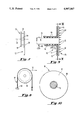
- FIG. 3 illustrates in diagrammatic form, a beam on which yarn or paper is wrapped and a brake wheel
- FIG. 4 is a side view taken along the line IV--IV of FIG. 3;
- FIG. 5 illustrates in diagrammatic form a supported brake band according to the invention as applied to the brake wheel shown in FIG. 3;
- FIG. 6 is a side view of FIG. 5;
- FIG. 7 illustrates in diagrammatic form an unsupported brake band according to the invention as applied to a spool on which woven tape, yarn, paper or the like is wrapped;
- FIG. 8 is a side view of the spool shown in FIG. 7;
- FIG. 9 is a diagrammatic fragmentary vertical sectional view of a brake disk according to the invention.
- FIG. 10 is a view taken along the line X--X of FIG. 9;
- FIG. 11 is a diagrammatic fragmentary vertical sectional view of a friction disk or clutch or torque limiter apparatus in accordance with the invention.
- FIG. 12 is a view taken along the line XII--XII of FIG. 11;
- FIG. 13 is a diagrammatic front view of a disk fabricated from thin strips of the fabric in accordance with the invention.
- FIG. 14 is a side view of FIG. 13.
- the lining member 10 comprises a sheet-like body with a friction surface 11.
- the sheet-like body includes a woven fabric, which includes warp yarns 12 and filling yarns 14, and a cured synthetic resin 16.
- the woven fabric of lining member 10 is constructed to present the warp yarns 12 at the wear face of friction surface 11.
- the filling yarns 14 comprise the support or reinforced backing of the lining member 10.
- the woven fabric of warp and filling yarns is impregnated with a thermosetting or thermoplastic resin 16 for support.
- the resulting high-strength composite can be cut to size and is easily secured to or bonded to any flat or curved surface with the resin, a suitable adhesive or other fastening means.
- the warp yarn 12 is made of a bundle 19 of filaments or fibers 20 and the backing, reinforcing or filling yarn 14 is made of a bundle 22 of filaments or fibers 24.
- the fibers 20 of the warp yarn 12 are fluorine fibers or a combination of fluorine fibers and other suitable fibers.
- fluorine fibers are available as Teflon which is a trademark of E.I. DuPont Company for its tetrafluorethylene (TFE) filament or as Goretex which is a trademark of W.L. Gore Company.
- polyester fibers such as Dupont brand Dacron and Kodak's brand Kodel
- aramid fibers such as Dupont brand Kevlar
- nylon fibers such as Dupont, brand Nomex, cotton fibers, PEEK and P.B.I. as manufactured by Celanese Corporation
- PPS fibers as manufactured by Phillips Ryton Corporation
- glass fibers ceramic fibers, asbestos fibers, steel fibers, stainless steel fibers, bronze fibers, carbon fibers, graphite fibers or boron fibers or a combination of one or more of such fibers.
- the warp yarn 12 is comprised of Teflon fibers and one or more of the above mentioned reinforcing fibers.
- the warp yarn 12 may have a content ratio of about 50% Teflon to 50% reinforcing fibers.
- Teflon to reinforcing fibers may be utilized depending upon the desired coefficient of friction, heat resistance, mechanical strength, wear resistance and heat stability of the resultant woven fabric and the resultant lining member.
- the fibers 20 and 24, of each bundle 19 and 22, respectively, may be twisted or have a zero twist or may be a combination of twisted and zero twist fibers.
- the fibers 20 either a single type fiber, or a combination of fibers, i.e., a multicomponent warp yarn, as described above, are formed into the yarn 12.
- the fibers 24, either a single type fiber or a combination of fibers, i.e. a multicomponent reinforcing yarn, as described above, are formed into the yarn 14.
- the yarns 12 and 14 are then woven into the fabric shown in FIG. 1 which, as shown, comprises a satin-weave fabric, with a 3:1 face, i.e. the ratio of Teflon fibers to reinforcing fibers at the face of the fabric is 3 to 1 or the warp yarns weave over 3 and under 1 filling yarn throughout the fabric. It is to be understood, however, that any ratio desired may be chosen and that the weave does not have to be a satin-weave.
- the advantages in accordance with the invention and a similar effect can be obtained by reversing the warp and filling yarns such that the warp yarns become the binders and the filling yarns become the TFE friction face; in other words, the underside of the liner would be used as a friction face.
- the woven fabric comprising the yarns 12 and 14, however constructed, is then impregnated with a suitable supporting or reinforcing resin and cured.
- Thermosetting resins such as various phenolics and polymides commercially available are suitable.
- FE 7119 brand resin manufactured by H.B. Fuller Company of Minneapolis, Minn., would be a suitable resin.
- thermoplastic resin such as PEEK resin manufactured by Celanese Corporation or PTFE resin manufactured by E.I. DuPont Company could also be used.
- the resulting composite is a flexible sheet-like lining material having a thickness in the range of 0.38 mm to 0.76 mm and preferably 0.50 mm which is suitable for use in various applications, examples of which will be set forth with reference to FIGS. 3-12.
- the liner can be laminated in thickness up to about 13 mm or larger for various applications in accordance with the invention.
- a method of making the lining member 10 is disclosed in U.S. Pat. No. 3,765,978, which patent is hereby incorporated by reference. Two examples of the fabric in accordance with the invention will be given wherein the warp and filling yarns are reversed from that shown in FIG. 1, i.e., the fibers of the filling yarns are comprised of Teflon fibers.
- a satin weave fabric can be produced comprising a 200 denier 100 filaments Nomex warp yarn, type 430, 6.0 twists per inch ("tpi") and a multi-component filament filling yarn comprising a 200 denier, 30 filament Teflon yarn and 200 denier, 100 filament Nomex yarn twisted together with 6.0 tpi.
- the fabric is thoroughly washed in boiling water to remove any water soluble sizing.
- the fabric is then dried and suitably coated with a resin adhesive.
- the adhesive may be a solvent based phenolic resin, epoxy, FEP or polyimide.
- the resin is then partially cured or so-called "B" staged so that it has a dry feel and can be readily handled.
- the "B" staged liner can now, if desired, be cut to size and be bonded to a supporting member such as a support disk by applying additional resin together with heat and pressure in a heated press.
- the resulting brake tensioning plate will exhibit superior wear and slip characteristics when compared to a PTFE resin face or a Nomex fabric face.
- the fabric is the same as that in Example One except that PEEK fibers are used (175 denier, 20 filaments) in place of Nomex yarn and the material after "B" staging is cut in strips and spirally wound and press cured in a heated mold to produce the disk illustrated in FIGS. 13 and 14.
- FIG. 3 illustrates in diagrammatic form a beam shown generally at 30 on which yarn, paper or the like may be wound.
- the beam 30 includes a core or center member 32 on which the material is actually wound and opposite end members 34 and 36.
- a shaft 38 extends through the beam to which the center member 32 is affixed.
- the shaft 38 is rotatably supported in some fashion by suitable support means represented in FIG. 3 by the arrows 39.
- the shaft 38 and center member 32 rotate as a unit.
- Material, designated by the reference numeral 40 is shown as being wound on the center member 32.
- the material 40 is designated as being unwound from the beam 30 as the beam 30 rotates in the direction of the arrow, i.e., clockwise.
- Mounted on the right side of shaft 38 to rotate therewith is a brake wheel 42.
- the friction apparatus or break means 44 comprises a brake band comprising a supporting member or band 46 of steel or other suitable material and a liner member 10, as described above, secured to the supporting member or band 46 by an adhesive or other suitable means.
- the brake band 46 is shown as secured at one end thereof as at 48, to a fixed support and at the other end thereof, has an adjustable force applied thereto such as, for example, by a weight, as designated by the letter W.
- the beam 30 rotates in a clockwise direction, as seen in FIG. 4, and since the liner member 10 is in frictional contact with the periphery 49 of brake wheel 42, the frictional force on the periphery 49 of brake wheel 42 developed by the sliding movement of the periphery 49 of the brake wheel 42 under the frictional surface of the liner member 10 effects a braking or tensioning action on the rotation of the beam 30 with the result that material 40 being unwound from the beam 30 is maintained under tension.
- the force applied to the end of the brake means 44 or weight W maintains the liner member 10 in frictional contact with the periphery 49 of brake wheel 42.
- this force or weight must be varied due to the changing radius of the material 40 on the beam 30 in order to maintain a relatively constant tensioning or braking action on brake wheel 42. If the unwinding of the material 40 is very, very slow, then the weight W can be changed by hand. If, however, the material is unwound at a rapid pace, then automatic weight adjusting means or some other suitable means such as, for example, a regulated air cylinder, can be utilized to apply a force to the end of the brake means 44.
- the brake means 44 permits sliding movement of the rotating brake wheel 42 with respect thereto and the force applied to the end of the brake means 44 maintains the friction surface of the liner 10 in contact with the rotating brake wheel 42 for effecting a relatively constant tensioning or braking effect on the rotating brake wheel 42.
- a spool is shown generally at 50 on which a woven tape or other material 52 is wound.
- the spool 50 like beam 30, includes a core or center member 54 and opposite end members 56 and 58.
- the spool 50 is rotatably supported by means (not shown) for rotation about an axis 60 passing through the center of member 54.
- the end member 58 has applied thereto break or tensioning means or brake band shown generally at 62.
- the break or tensioning means 62 comprises an unsupported strip of liner member lo, as described above.
- break means 62 is shown as secured at one end thereof, as at 64, to a fixed support and at the other end thereof, has an adjustable force applied thereto such as, for example, by a weight W.
- the essential difference between the brake means 44 and 62 is that brake means 62 is unsupported, i.e., it does not have a member comparable to supporting member or band 46. Otherwise, operation of the break means 62 is the same as that given above with reference to brake means 44.
- FIG. 9 illustrates a diagrammatic fragmentary vertical sectional view of a friction or brake disk, shown generally at 66.
- the friction or brake disk 66 comprises an annular supporting disk 68 to which is secured an annular liner member 10.
- the liner member 10 is attached or secured to supporting disk 68 as by bonding with a suitable adhesive, rivets, screws or other suitable means.
- a member, shown generally at 70 with which brake disk 66 coacts.
- Member 70 comprises a annular metal plate 72 to which is welded, or otherwise secured, a tubular member 74. Together, the members 72 and 74 are fixed against rotation as indicated at 75 and would form a part of a larger piece of equipment or machinery, not shown.
- the disk 68 is secured to a shaft 76 which is mounted for rotation, as designated by the arrow 78, and disk 68 rotates with shaft 76.
- roller bearings 80 are provided between tubular member 74 and shaft 76.
- the arrows 82 in FIG. 9 indicate the application of a force or pressure against brake disk 66 to effect frictional engagement between annular liner member 10 and the annular surface of annular metal plate 72.
- braking effect is to be construed in its broadest sense, i.e., to include a slowing, tensioning, slip or sliding action and not be limited solely to a stopping action.
- the pressure could be applied to the disk 66 in a member of a well known ways and by various apparatus. As for example, the pressure may be applied by weights, springs, air diaphragms, fluid diaphragms or by electro-magnetic means.
- FIG. 11 illustrates a friction disk or clutch or torque limiter apparatus in accordance with the invention.
- the apparatus shown in FIG. 11 comprises an annular disk 90 secured to a shaft 92.
- Shaft 92 and disk 90 are mounted for rotation as indicated by the arrow 94.
- Bonded or otherwise secured to the disk 90 are a plurality of liner members 10 in the form of segments.
- a second annular disk 96 is secured to a shaft 98.
- the shaft 98 and disk 90 are mounted for rotation as indicated by the arrow 100. While the liner members 10 have been illustrated as secured to the disk 90 they could just as easily be secured to the disk 96.
- the shaft 92 and disk 90 will be considered a rotating driving member which may be driven directly or indirectly by an suitable means, as for example, by an electric motor, and disk 96 and shaft 98 will be considered a rotating driven member.
- either or both shafts 96, 98 can be mounted for relative horizontal movement as indicated by the arrows 102 and 104 in order to effect relative movement of disks 90 and 96 towards and away from each other.
- lining members 10 have been shown as secured to disk 90, lining members 10 may be secured to disk 96.
- disks 90 and 96 are shown as single disks, they may each comprise a plurality of interleaved disks with a plurality of lining members 10 secured to either the plurality of disks 90 or to the plurality of disks 96.
- disk 96 and shaft 98 In operation, with shaft 92 being driven and with liner member 10 in frictional contact with disk 96, disk 96 and shaft 98 will rotate and be driven due to the clutching action effected by the liners 10 on the surface of the disk 96.
- the apparatus illustrated in FIGS. 11 and 12, in addition to being representative of a clutch means, can also be considered as representative of a torque limiting means or device.
- the driving member (shaft 92 and disk 90) can be arranged to effect relative slippage between the driving member and the driven member (disk 96 and shaft 98) when input torque to the driven member exceeds a predetermined value or the load on the driven member exceeds a predetermined value.
- FIG. 13 is a diagrammatic front view of disk 110 fabricated from thin strips of the sheet liner material described herein and exemplified in FIG. 1.
- the sheet liner material can be cut or slit into narrow strips or tapes. Continuous lengths of the tape can then be wound on a mandrel to form the disk 110. Thereafter, the disk 110 would be inserted into a suitable heated mold cavity for press curing into a solid disk as shown in FIGS. 13 and 14. Portions of the fluorine fibers used to construct the sheet liner material would be presented, together with portions of other fibers utilized to make the fabric of the liner, at the opposite surfaces 112 and 114. The surfaces 112 and 114 provide friction surfaces as hereinbefore described.
- the disk 110 can be used alone or may be bonded or otherwise secured to a support member.
- Lining members according to the invention when forming a part of tensioning devices, brakes, clutches, torque limiters or other suitable friction apparatus offer significant advantages.
- the liner in accordance with the invention is lightweight and because the combination of yarn types and resin types utilized produces a hard wearing material, the liner can be used in thin sheets. Because the liner sheets are thin, they are not only lightweight and cost effective, but also have good thermal properties and allow heat to dissipate from the friction face or surface to the backing of the liner. Lining members in accordance with the invention have been tested to have a uniform coefficient of friction through a temperature range from about 65° F. to about 300° F. and depending on the resin system, it is believed can have a uniform coefficient of friction through a temperature range from about 65° F.
- the lining members 10 have static and dynamic coefficients of friction which are substantially equal thereby eliminating stick-slip operation in the types of apparatus in which they are employed.
- the liner member 10 can be utilized in various apparatus such as tensioning devices, brakes, clutches, torque limiters and the like and in applications wherein it is desired to have a uniform or constant tensioning or slip friction surface for effecting braking, clutching or torque limiting action. It will also be understood that, while the liner member 10 has been described in detail above as comprising a woven fabric, the invention is not so limited as the fabric may also be non-woven, braided or knitted if so desired. The incorporation of heat and wear resistant fluorine fibers in such fabrics will also produce liner member having the desired constant slip friction surface in accordance with the invention.
Abstract
Description
Claims (15)
Priority Applications (1)
| Application Number | Priority Date | Filing Date | Title |
|---|---|---|---|
| US07/371,429 US4997067A (en) | 1989-06-26 | 1989-06-26 | Friction apparatus |
Applications Claiming Priority (1)
| Application Number | Priority Date | Filing Date | Title |
|---|---|---|---|
| US07/371,429 US4997067A (en) | 1989-06-26 | 1989-06-26 | Friction apparatus |
Publications (1)
| Publication Number | Publication Date |
|---|---|
| US4997067A true US4997067A (en) | 1991-03-05 |
Family
ID=23463959
Family Applications (1)
| Application Number | Title | Priority Date | Filing Date |
|---|---|---|---|
| US07/371,429 Expired - Fee Related US4997067A (en) | 1989-06-26 | 1989-06-26 | Friction apparatus |
Country Status (1)
| Country | Link |
|---|---|
| US (1) | US4997067A (en) |
Cited By (29)
| Publication number | Priority date | Publication date | Assignee | Title |
|---|---|---|---|---|
| EP0687829A1 (en) | 1994-06-17 | 1995-12-20 | Wagner Electric Corporation | Reinforced friction material |
| US5576358A (en) * | 1995-02-03 | 1996-11-19 | Alliedsignal Inc. | Composition for use in friction materials and articles formed therefrom |
| US5615758A (en) * | 1994-09-30 | 1997-04-01 | Nels; Terry E. | Fabric arrangement and method for controlling fluid flow |
| EP0892191A1 (en) * | 1996-02-23 | 1999-01-20 | Anatoly Veniaminovich Pinkhasovich | Reinforcing filler, friction polymer composite material and a brake friction element |
| EP0992782A1 (en) * | 1998-10-06 | 2000-04-12 | Ion Track Instruments, Inc. | Materials and apparatus for the detection of contraband |
| US6065579A (en) * | 1994-09-30 | 2000-05-23 | Select Powertrain Technologies Corp. | Synchronizer blocker rings used in manual transmissions |
| US6247499B1 (en) * | 1999-08-13 | 2001-06-19 | Ico, Inc. | Pipe wrap corrosion protection system |
| US6488133B1 (en) * | 1997-09-29 | 2002-12-03 | Inertia Dynamics, Inc. | Clutch system and method |
| US6675939B2 (en) | 2001-01-31 | 2004-01-13 | Inertia Dynamics, Inc. | Elevator brake assembly |
| US20050011720A1 (en) * | 2003-07-14 | 2005-01-20 | Adair Jeffrey W. | Friction material having oil localization slots |
| US6875473B2 (en) * | 2001-01-08 | 2005-04-05 | J. D. Lincoln, Inc. | Woven fabric with a modified ester resin for use as a wet friction liner |
| US20050075019A1 (en) * | 2003-10-03 | 2005-04-07 | Lam Robert C. | High coefficient woven friction material |
| US20050074595A1 (en) * | 2003-10-03 | 2005-04-07 | Lam Robert C. | Friction material containing partially carbonized carbon fibers |
| US20050075022A1 (en) * | 2003-10-03 | 2005-04-07 | Lam Robert C. | Elastic and porous friction material with high amount of fibers |
| US20050241907A1 (en) * | 2004-04-28 | 2005-11-03 | Gregory Mordukhovich | Woven composite clutch friction member with dual-directional moduli of elasticity |
| US20050281971A1 (en) * | 2004-06-18 | 2005-12-22 | Lam Robert C | Fully fibrous structure friction material |
| US20060116622A1 (en) * | 2003-06-24 | 2006-06-01 | Pike Anthony B | Medical protection sheeting |
| US20060175162A1 (en) * | 2005-02-04 | 2006-08-10 | Thorp John H E | Reinforced brake lining and method of producing |
| US20060241207A1 (en) * | 2005-04-26 | 2006-10-26 | Borgwarner Inc. | Friction material |
| US20090036010A1 (en) * | 2007-08-03 | 2009-02-05 | Borgwarner Inc. | Friction material with silicon |
| US20090324887A1 (en) * | 2008-06-30 | 2009-12-31 | Borgwarner Inc. | Friction materials |
| US20100155189A1 (en) * | 2006-05-01 | 2010-06-24 | Danaher Motion | Braking or clutching device |
| US7749562B1 (en) | 2004-07-26 | 2010-07-06 | Borgwarner Inc. | Porous friction material comprising nanoparticles of friction modifying material |
| US20100304631A1 (en) * | 2005-11-02 | 2010-12-02 | Borgwarner Inc. | Carbon Friction Materials |
| US8397889B2 (en) | 2008-03-12 | 2013-03-19 | Borgwarner Inc. | Frictional device comprising at least one friction plate |
| US8603614B2 (en) | 2004-07-26 | 2013-12-10 | Borgwarner Inc. | Porous friction material with nanoparticles of friction modifying material |
| US20150308532A1 (en) * | 2012-07-23 | 2015-10-29 | Hitachi Chemical Company, Ltd. | Brake pad for yaw control, and brake member |
| US20190101173A1 (en) * | 2017-09-29 | 2019-04-04 | Robert Bosch Llc | Additively-Manufactured Brake Pad Assembly with Controlled Compressibility Factor |
| EP3333289A4 (en) * | 2015-08-05 | 2019-08-21 | Toray Industries, Inc. | Self lubricating fabric, method for production and use thereof |
Citations (26)
| Publication number | Priority date | Publication date | Assignee | Title |
|---|---|---|---|---|
| US2599826A (en) * | 1946-12-06 | 1952-06-10 | Johns Manyille Corp | Reinforced friction facing |
| US2702770A (en) * | 1951-08-14 | 1955-02-22 | Raybestos Manhattan Inc | Production of friction materials |
| US2728700A (en) * | 1953-03-16 | 1955-12-27 | Thomas L Gatke | Friction member |
| US2809130A (en) * | 1956-05-18 | 1957-10-08 | Gen Motors Corp | Method of bonding a fluorinated synthetic resin to another material |
| US3085667A (en) * | 1959-09-10 | 1963-04-16 | Sperry Rand Corp | Clutch brake friction disk |
| US3365041A (en) * | 1965-10-21 | 1968-01-23 | Raybestos Manhattan Inc | Clutch facing |
| US3526306A (en) * | 1968-02-08 | 1970-09-01 | Raybestos Manhattan Inc | Clutch facing |
| US3617426A (en) * | 1969-03-10 | 1971-11-02 | Minnesota Mining & Mfg | Torque-transmitting member |
| US3664472A (en) * | 1969-12-10 | 1972-05-23 | Messgeratewerk Zwonitz K Veb | Coupling with thermoplastic and cellulosic friction disc |
| US3684062A (en) * | 1969-02-14 | 1972-08-15 | Kelsey Hayes Co | Friction lining composition |
| US3710905A (en) * | 1970-08-13 | 1973-01-16 | Minnesota Mining & Mfg | Torque transmitting device |
| US3712428A (en) * | 1970-06-22 | 1973-01-23 | Carborundum Co | Reinforced carbon bodies |
| US3765978A (en) * | 1971-07-08 | 1973-10-16 | Textron Inc | Method of making a low-friction fabric bearing |
| US3860094A (en) * | 1972-12-26 | 1975-01-14 | Roger Breton | Self-tightening brake for bicycles, motorcycles and the like |
| US3868002A (en) * | 1972-10-03 | 1975-02-25 | Raymond Babled | Brake members and shoes and shoe supports for such members, especially for two-wheeled vehicles |
| US4291794A (en) * | 1979-10-10 | 1981-09-29 | The B. F. Goodrich Company | Power transmission and energy absorbing systems |
| US4344615A (en) * | 1980-04-10 | 1982-08-17 | Carlson Charles H | Controlled friction exercising device |
| US4384640A (en) * | 1979-06-21 | 1983-05-24 | Raymark Corporation | Friction material for clutch facings and the like |
| US4539240A (en) * | 1984-11-29 | 1985-09-03 | Borg-Warner Corporation | Asbestos free friction element |
| US4585098A (en) * | 1982-06-18 | 1986-04-29 | D.A.B. Industries, Inc. | Filament-reinforced composite transmission brake band |
| US4593802A (en) * | 1983-10-11 | 1986-06-10 | The S. K. Wellman Company | Friction material |
| US4700823A (en) * | 1980-03-28 | 1987-10-20 | Eaton Corporation | Clutch with pyrolytic carbon friction material |
| US4728552A (en) * | 1984-07-06 | 1988-03-01 | Rodel, Inc. | Substrate containing fibers of predetermined orientation and process of making the same |
| US4762216A (en) * | 1987-06-03 | 1988-08-09 | Eaton Corporation | Vehicle component having improved friction material |
| US4778548A (en) * | 1987-07-24 | 1988-10-18 | Fox Joseph R | Bonding woven carbon fabric friction materials |
| US4781275A (en) * | 1984-04-30 | 1988-11-01 | Amsted Industries Incorporated | Composition railway brake shoe |
-
1989
- 1989-06-26 US US07/371,429 patent/US4997067A/en not_active Expired - Fee Related
Patent Citations (27)
| Publication number | Priority date | Publication date | Assignee | Title |
|---|---|---|---|---|
| US2599826A (en) * | 1946-12-06 | 1952-06-10 | Johns Manyille Corp | Reinforced friction facing |
| US2702770A (en) * | 1951-08-14 | 1955-02-22 | Raybestos Manhattan Inc | Production of friction materials |
| US2728700A (en) * | 1953-03-16 | 1955-12-27 | Thomas L Gatke | Friction member |
| US2809130A (en) * | 1956-05-18 | 1957-10-08 | Gen Motors Corp | Method of bonding a fluorinated synthetic resin to another material |
| US3085667A (en) * | 1959-09-10 | 1963-04-16 | Sperry Rand Corp | Clutch brake friction disk |
| US3365041A (en) * | 1965-10-21 | 1968-01-23 | Raybestos Manhattan Inc | Clutch facing |
| US3526306A (en) * | 1968-02-08 | 1970-09-01 | Raybestos Manhattan Inc | Clutch facing |
| US3684062A (en) * | 1969-02-14 | 1972-08-15 | Kelsey Hayes Co | Friction lining composition |
| US3617426A (en) * | 1969-03-10 | 1971-11-02 | Minnesota Mining & Mfg | Torque-transmitting member |
| US3664472A (en) * | 1969-12-10 | 1972-05-23 | Messgeratewerk Zwonitz K Veb | Coupling with thermoplastic and cellulosic friction disc |
| US3712428A (en) * | 1970-06-22 | 1973-01-23 | Carborundum Co | Reinforced carbon bodies |
| US3710905A (en) * | 1970-08-13 | 1973-01-16 | Minnesota Mining & Mfg | Torque transmitting device |
| US3765978A (en) * | 1971-07-08 | 1973-10-16 | Textron Inc | Method of making a low-friction fabric bearing |
| US4074512A (en) * | 1971-07-08 | 1978-02-21 | Textron, Inc. | Low-friction fabric bearing |
| US3868002A (en) * | 1972-10-03 | 1975-02-25 | Raymond Babled | Brake members and shoes and shoe supports for such members, especially for two-wheeled vehicles |
| US3860094A (en) * | 1972-12-26 | 1975-01-14 | Roger Breton | Self-tightening brake for bicycles, motorcycles and the like |
| US4384640A (en) * | 1979-06-21 | 1983-05-24 | Raymark Corporation | Friction material for clutch facings and the like |
| US4291794A (en) * | 1979-10-10 | 1981-09-29 | The B. F. Goodrich Company | Power transmission and energy absorbing systems |
| US4700823A (en) * | 1980-03-28 | 1987-10-20 | Eaton Corporation | Clutch with pyrolytic carbon friction material |
| US4344615A (en) * | 1980-04-10 | 1982-08-17 | Carlson Charles H | Controlled friction exercising device |
| US4585098A (en) * | 1982-06-18 | 1986-04-29 | D.A.B. Industries, Inc. | Filament-reinforced composite transmission brake band |
| US4593802A (en) * | 1983-10-11 | 1986-06-10 | The S. K. Wellman Company | Friction material |
| US4781275A (en) * | 1984-04-30 | 1988-11-01 | Amsted Industries Incorporated | Composition railway brake shoe |
| US4728552A (en) * | 1984-07-06 | 1988-03-01 | Rodel, Inc. | Substrate containing fibers of predetermined orientation and process of making the same |
| US4539240A (en) * | 1984-11-29 | 1985-09-03 | Borg-Warner Corporation | Asbestos free friction element |
| US4762216A (en) * | 1987-06-03 | 1988-08-09 | Eaton Corporation | Vehicle component having improved friction material |
| US4778548A (en) * | 1987-07-24 | 1988-10-18 | Fox Joseph R | Bonding woven carbon fabric friction materials |
Non-Patent Citations (1)
| Title |
|---|
| Fenner Manheim Product Bulletin (1988). * |
Cited By (50)
| Publication number | Priority date | Publication date | Assignee | Title |
|---|---|---|---|---|
| US5861203A (en) * | 1994-06-17 | 1999-01-19 | Wagner Electric Corporation | Reinforced friction material |
| EP0687829A1 (en) | 1994-06-17 | 1995-12-20 | Wagner Electric Corporation | Reinforced friction material |
| US6439363B1 (en) | 1994-09-30 | 2002-08-27 | Select Powertrain Technologies Corp. | Fabric arrangement and method for controlling fluid flow |
| US5615758A (en) * | 1994-09-30 | 1997-04-01 | Nels; Terry E. | Fabric arrangement and method for controlling fluid flow |
| US5842551A (en) * | 1994-09-30 | 1998-12-01 | Nels; Terry E. | Fabric arrangement and method for controlling fluid flow |
| US5998311A (en) * | 1994-09-30 | 1999-12-07 | Nels; Terry E. | Fabric arrangement and method for controlling fluid flow |
| US6065579A (en) * | 1994-09-30 | 2000-05-23 | Select Powertrain Technologies Corp. | Synchronizer blocker rings used in manual transmissions |
| US5576358A (en) * | 1995-02-03 | 1996-11-19 | Alliedsignal Inc. | Composition for use in friction materials and articles formed therefrom |
| EP0892191A1 (en) * | 1996-02-23 | 1999-01-20 | Anatoly Veniaminovich Pinkhasovich | Reinforcing filler, friction polymer composite material and a brake friction element |
| EP0892191A4 (en) * | 1996-02-23 | 1999-05-19 | Anatoly Veniamino Pinkhasovich | Reinforcing filler, friction polymer composite material and a brake friction element |
| US6488133B1 (en) * | 1997-09-29 | 2002-12-03 | Inertia Dynamics, Inc. | Clutch system and method |
| EP0992782A1 (en) * | 1998-10-06 | 2000-04-12 | Ion Track Instruments, Inc. | Materials and apparatus for the detection of contraband |
| US6642513B1 (en) | 1998-10-06 | 2003-11-04 | General Electric Company | Materials and apparatus for the detection of contraband |
| US20040094707A1 (en) * | 1998-10-06 | 2004-05-20 | General Electric Company | Materials and apparatus for the detection of contraband |
| US6815670B2 (en) | 1998-10-06 | 2004-11-09 | General Electric Company | Materials and apparatus for the detection of contraband |
| US6247499B1 (en) * | 1999-08-13 | 2001-06-19 | Ico, Inc. | Pipe wrap corrosion protection system |
| US6875473B2 (en) * | 2001-01-08 | 2005-04-05 | J. D. Lincoln, Inc. | Woven fabric with a modified ester resin for use as a wet friction liner |
| US6675939B2 (en) | 2001-01-31 | 2004-01-13 | Inertia Dynamics, Inc. | Elevator brake assembly |
| US20060116622A1 (en) * | 2003-06-24 | 2006-06-01 | Pike Anthony B | Medical protection sheeting |
| US20050011720A1 (en) * | 2003-07-14 | 2005-01-20 | Adair Jeffrey W. | Friction material having oil localization slots |
| US7014027B2 (en) | 2003-07-14 | 2006-03-21 | Borgwarner Inc. | Friction material having oil localization slots |
| US20050074595A1 (en) * | 2003-10-03 | 2005-04-07 | Lam Robert C. | Friction material containing partially carbonized carbon fibers |
| US20050075021A1 (en) * | 2003-10-03 | 2005-04-07 | Lam Robert C. | High performance, durable, deposit friction material |
| US20050075022A1 (en) * | 2003-10-03 | 2005-04-07 | Lam Robert C. | Elastic and porous friction material with high amount of fibers |
| US20050075019A1 (en) * | 2003-10-03 | 2005-04-07 | Lam Robert C. | High coefficient woven friction material |
| US20050241907A1 (en) * | 2004-04-28 | 2005-11-03 | Gregory Mordukhovich | Woven composite clutch friction member with dual-directional moduli of elasticity |
| CN100406763C (en) * | 2004-04-28 | 2008-07-30 | 通用汽车公司 | Woven composite clutch friction member with dual-directional moduli of elasticity |
| US7028823B2 (en) * | 2004-04-28 | 2006-04-18 | General Motors Corporation | Woven composite clutch friction member with dual-directional moduli of elasticity |
| US20050281971A1 (en) * | 2004-06-18 | 2005-12-22 | Lam Robert C | Fully fibrous structure friction material |
| US8021744B2 (en) | 2004-06-18 | 2011-09-20 | Borgwarner Inc. | Fully fibrous structure friction material |
| US7749562B1 (en) | 2004-07-26 | 2010-07-06 | Borgwarner Inc. | Porous friction material comprising nanoparticles of friction modifying material |
| US8603614B2 (en) | 2004-07-26 | 2013-12-10 | Borgwarner Inc. | Porous friction material with nanoparticles of friction modifying material |
| US7225904B2 (en) * | 2005-02-04 | 2007-06-05 | Goodrich Corporation | Reinforced brake lining and method of producing |
| US20060175162A1 (en) * | 2005-02-04 | 2006-08-10 | Thorp John H E | Reinforced brake lining and method of producing |
| US20060241207A1 (en) * | 2005-04-26 | 2006-10-26 | Borgwarner Inc. | Friction material |
| US7806975B2 (en) | 2005-04-26 | 2010-10-05 | Borgwarner Inc. | Friction material |
| US8394452B2 (en) | 2005-11-02 | 2013-03-12 | Borgwarner Inc. | Carbon friction materials |
| US20100304631A1 (en) * | 2005-11-02 | 2010-12-02 | Borgwarner Inc. | Carbon Friction Materials |
| US20100155189A1 (en) * | 2006-05-01 | 2010-06-24 | Danaher Motion | Braking or clutching device |
| EP2302250A1 (en) * | 2006-05-01 | 2011-03-30 | Danaher Motion | A braking or clutching device |
| US8371423B2 (en) * | 2006-05-01 | 2013-02-12 | American Precision Industries, Inc. | Braking or clutching device |
| US20090036010A1 (en) * | 2007-08-03 | 2009-02-05 | Borgwarner Inc. | Friction material with silicon |
| US8397889B2 (en) | 2008-03-12 | 2013-03-19 | Borgwarner Inc. | Frictional device comprising at least one friction plate |
| US20090324887A1 (en) * | 2008-06-30 | 2009-12-31 | Borgwarner Inc. | Friction materials |
| US9939036B2 (en) | 2008-06-30 | 2018-04-10 | Borgwarner Inc. | Friction materials |
| US20150308532A1 (en) * | 2012-07-23 | 2015-10-29 | Hitachi Chemical Company, Ltd. | Brake pad for yaw control, and brake member |
| US9568061B2 (en) * | 2012-07-23 | 2017-02-14 | Hitachi Chemical Company, Ltd. | Brake pad for yaw control, and brake member |
| EP3333289A4 (en) * | 2015-08-05 | 2019-08-21 | Toray Industries, Inc. | Self lubricating fabric, method for production and use thereof |
| US20190101173A1 (en) * | 2017-09-29 | 2019-04-04 | Robert Bosch Llc | Additively-Manufactured Brake Pad Assembly with Controlled Compressibility Factor |
| US10690201B2 (en) * | 2017-09-29 | 2020-06-23 | Robert Bosch Llc | Additively-manufactured brake pad assembly with controlled compressibility factor |
Similar Documents
| Publication | Publication Date | Title |
|---|---|---|
| US4997067A (en) | Friction apparatus | |
| US3552533A (en) | Carbonized friction article | |
| US3707752A (en) | Roll covering | |
| US3365041A (en) | Clutch facing | |
| US3639197A (en) | Carbon composite structure including a band of helically wound carbon fibers | |
| US3936552A (en) | Nonmetallic composite friction member | |
| US3934686A (en) | Carbon friction members having torque transmitting formations | |
| GB1128360A (en) | Clutch facing | |
| JPH0434217A (en) | Slip clutch | |
| US3741855A (en) | Low friction bearing materials | |
| US5311094A (en) | Ultrasonic motor | |
| EP2126206A1 (en) | Roll cover and a covered roll | |
| US3600258A (en) | Friction facing comprising a tape of material of at least one strand of glass yarn and at least one strand of asbestos yarn in side-by-side relationship | |
| JP2004238615A (en) | Mono-directional prepreg, method for manufacturing fiber reinforced sheet and apparatus for the same | |
| JP2002003280A (en) | Sliding member of carbon-fiber-reinforced carbon and its manufacturing method | |
| US3141806A (en) | Apparatus for forming a wound hollow structure of fiber reinforced tape | |
| CA1224163A (en) | Filament-reinforced composite transmission/brake band and method and apparatus for making the same | |
| US20150362016A1 (en) | Plain bearing | |
| JPH0796273B2 (en) | Method of making rings of gears with internal and external teeth and use of said composite rings for making internal or external gears | |
| US3713934A (en) | Method of producing friction facings | |
| US3900408A (en) | Bearing liner | |
| EP2955401B1 (en) | Plain bearing | |
| JPS6258887A (en) | Ultrasonic motor | |
| US5171620A (en) | Honeycomb core | |
| US2855081A (en) | Clutch facing |
Legal Events
| Date | Code | Title | Description |
|---|---|---|---|
| AS | Assignment |
Owner name: FENNER AMERICA, INC., PENNSYLVANIA Free format text: ASSIGNMENT OF ASSIGNORS INTEREST.;ASSIGNOR:WATTS, ANTHONY P.;REEL/FRAME:005096/0598 Effective date: 19890622 |
|
| FPAY | Fee payment |
Year of fee payment: 4 |
|
| FPAY | Fee payment |
Year of fee payment: 8 |
|
| REMI | Maintenance fee reminder mailed | ||
| LAPS | Lapse for failure to pay maintenance fees | ||
| LAPS | Lapse for failure to pay maintenance fees |
Free format text: PATENT EXPIRED FOR FAILURE TO PAY MAINTENANCE FEES (ORIGINAL EVENT CODE: EXP.); ENTITY STATUS OF PATENT OWNER: LARGE ENTITY |
|
| STCH | Information on status: patent discontinuation |
Free format text: PATENT EXPIRED DUE TO NONPAYMENT OF MAINTENANCE FEES UNDER 37 CFR 1.362 |
|
| FP | Lapsed due to failure to pay maintenance fee |
Effective date: 20030305 |