US5014720A - Lead to electrode joint assembly and method of manufacture thereof - Google Patents
Lead to electrode joint assembly and method of manufacture thereof Download PDFInfo
- Publication number
- US5014720A US5014720A US07/461,703 US46170390A US5014720A US 5014720 A US5014720 A US 5014720A US 46170390 A US46170390 A US 46170390A US 5014720 A US5014720 A US 5014720A
- Authority
- US
- United States
- Prior art keywords
- coil
- electrode
- press tube
- counterbore
- minor
- Prior art date
- Legal status (The legal status is an assumption and is not a legal conclusion. Google has not performed a legal analysis and makes no representation as to the accuracy of the status listed.)
- Expired - Lifetime
Links
Images

Classifications
-
- A—HUMAN NECESSITIES
- A61—MEDICAL OR VETERINARY SCIENCE; HYGIENE
- A61N—ELECTROTHERAPY; MAGNETOTHERAPY; RADIATION THERAPY; ULTRASOUND THERAPY
- A61N1/00—Electrotherapy; Circuits therefor
- A61N1/02—Details
- A61N1/04—Electrodes
- A61N1/05—Electrodes for implantation or insertion into the body, e.g. heart electrode
- A61N1/056—Transvascular endocardial electrode systems
Definitions
- the present invention relates to a new and improved joint assembly and to a method of achieving the novel joint assembly.
- the joint assembly of the invention may have particular application to pacemakers, and more specifically, for connecting a helically wound lead conductor coil to an electrode.
- Electrodes have been implanted by a thoracotomy in which an electrode formed on the end of the lead is physically implanted into the myocardial tissues.
- Electrodes attached to the heart are stimulated by a cardiac pacemaker which may be implanted within the patient's body.
- Bipolar systems utilizing coaxial leads have come to be widely used.
- coaxial leads the two conductors are shaped into a small helix surrounded by a larger helix resulting in a much smaller pulse generator connector block. Nonetheless, there is continuing emphasis on developing leads and connectors of ever smaller sizes.
- the present invention relates to a novel joint assembly which may be used for affixing a helically wound lead conductor coil to an electrode of a pacemaker.
- the electrode has a longitudinal bore and a coaxial counterbore.
- One end of the coil is fittingly attached to a reduced diameter end of a press tube.
- the outer diameter of the extreme outer surface of the coil on the press tube is slightly greater than the inner diameter of the counterbore in the electrode.
- the reduced diameter end of the press tube with the coil therein is fittingly inserted into the counterbore. This results in a solid connection between the lead conductor coil and the electrode without causing any visible alteration of the outer surface of the electrode.
- the technique of the invention provides for maximum diametric reduction of the electrode, and therefore, maximum weight reduction. Both of these are important considerations when designing down-sized endocardial pacing leads.
- the crimped electrode presently used has a diameter of approximately 0.094 inches.
- the assembly of the invention could be as small as 0.75 inches in diameter while still employing the same components.
- the invention simplifies known techniques and can result in a higher rate of manufacture and, therefore, productivity.
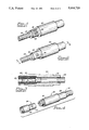
- FIG. 1 is a perspective view depicting a prior art coil to electrode connection which has been accomplished by welding;
- FIG. 2 is a perspective view of another prior art connection which has been accomplished by crimping
- FIG. 3 is a cross section view taken generally along line 3--3 in FIG. 2;
- FIG. 4 is a perspective exploded view illustrating primary components of the invention
- FIG. 5 is a side elevation view illustrating one step of a method resulting in the connection of the invention.
- FIG. 6 is a side elevation view of a completed connection of the invention.
- FIG. 7 is a cross section view taken generally along line 7--7 in FIG. 6.
- FIG. 1 illustrates an electrode 20 with a reduced end 22 to which a multiple winding helical coil 24 is joined.
- the coil 24 extends into a longitudinal bore 25 formed in the electrode.
- the reduced end 22 of the electrode 20 is provided with an elongated aperture 26 through which a plurality of ends 28 from the coil 24 project. The ends 28 are then spot or laser welded to the outer surface of the reduced end 22.
- Electrode 30 has a reduced end 32 to which a helical coil 34 is to be joined.
- Electrode 30 has a longitudinal bore 36 extending inwardly from one end and a counterbore 38 extending inwardly from an opposite end.
- the bore 36 and counterbore 38 meet at a modified shoulder 40 and the coil 34 is slidably received in the bore 36 and counterbore 38.
- a cylindrical crimp tube 42 is inserted into the counterbore 38 which enlarges the diameter of the coil 34 in the region of the counterbore 38.
- a suitable crimping tool is then employed to depress the reduced end 32 into firm engagement with the coil 34 at circumferentially spaced crimp regions 44 and the coil, in turn, into engagement with the crimp tube 42.
- the inner diameter of the crimp tube 42 must be sufficiently large to slidably receive an inner coil and its insulation (not shown).
- the inner coil and insulation combination is also slidably receivable within the coil 3 both within the bore 36 and as the coil extends to a distant location.
- the counterbore 38 is provided to accommodate the addition of the crimp tube 42, but of necessity, causes a reduced thickness of material at the reduced end 32 of the electrode 30.
- both the welded construction of FIG. and the crimped construction of FIGS. 2 and 3 have a number of drawbacks.
- the connection is not a uniform one but is substantially limited to the weld regions and to the crimp regions 44.
- a tubular electrode 46 which, in typical fashion, may be composed of a platinum iridium alloy.
- the electrode has a cylindrical outer surface 47 and is formed with a longitudinal bore 48 which extends inwardly from one end 50 and a counterbore 52 coaxial with the longitudinal bore 48 extending inwardly from an opposite end 54.
- the longitudinal bore 48 and counterbore 52 intersect at a modified shoulder 56.
- the electrode is formed with a cylindrical undercut surface 58 adjacent the end 50 which is generally coaxial with the cylindrical outer surface 47.
- a lead conductor 60 which may be formed as a multiple winding helical coil 62 is utilized by the invention and, in typical fashion, may be of MP 35N alloy manufactured by Latrobe Steel Company of Latrobe, Pa., or may be of other suitable metal.
- the coil 62 has a normal outer diameter slightly smaller than the inner diameter of the longitudinal bore 48 to enable slidable reception of the lead conductor 60 in the bore 48.
- the invention also utilizes a cylindrical press tube 64 which has a longitudinal bore 66 which may have an inner diameter substantially equal to that of the coil 62.
- the press tube 64 may be composed of a platinum iridium alloy like the electrode 46 or of AISI Type 316L stainless steel, or of other suitable material.
- the press tube 64 is also characterized as having a major end 68 with a major outer peripheral surface having an outer diameter substantially equal to the inner diameter of the counterbore 52, a minor end 70 with a minor outer peripheral surface having an outer diameter greater than the inner diameter of the longitudinal bore 48, and an annular shoulder 72 at the interface between the major outer surface and the minor outer surface.
- a proximal end of the coil 62 is threaded or otherwise forced onto the minor end 70 of the press tube 64 until it substantially engages the annular shoulder 72.
- This causes circumferential enlargement of the coil and the natural spring tension thereby created in the coil keeps it tightly affixed to the press tube.
- the coil 62 is affixed to the press tube 64 in the manner illustrated in FIG. 5, it presents an outer surface having an extreme outer diameter slightly greater than the inner diameter of the counterbore 52.
- a next step of the method of the invention is realized when the press tube 64 with coil 62 thereon is pressed in the direction of an arrow 74 such that the minor end 70 with coil 62 thereon is pressed into engagement with the counterbore 52. This step continues until a terminal surface of the minor end 70 is positioned proximate the shoulder 56. When this occurs, the minor end 70 is substantially coextensive with the counterbore 52.
- the interference fit which thereby results by reason of the engagement of the helical coil 62 with the counterbore 52 assures a strong and durable connection between the electrode and the lead connector 60. Additionally, the resultant connection presents no visible crimps or other assembly marks which would be detrimental to the operation of the electrode.
- Outer insulation tubing 76 which may be of polyurethane or other suitable insulating material, is fittingly applied to the surface 58 of the electrode 46 and generally overlies and insulates the coil 62 as it extends to a distant location.
- an inner lead conductor 77 may accompany the lead conductor 60. Its inner coil 78 and associated inner insulation 80 are slidably received within the bore 66 of the press tube 64 and within the interior of the coil 62.
- connection of the invention just described is strong and durable and of minimal diameter even as it provides for the inner lead conductor 77.
Abstract
Description
Claims (9)
Priority Applications (1)
| Application Number | Priority Date | Filing Date | Title |
|---|---|---|---|
| US07/461,703 US5014720A (en) | 1990-01-08 | 1990-01-08 | Lead to electrode joint assembly and method of manufacture thereof |
Applications Claiming Priority (1)
| Application Number | Priority Date | Filing Date | Title |
|---|---|---|---|
| US07/461,703 US5014720A (en) | 1990-01-08 | 1990-01-08 | Lead to electrode joint assembly and method of manufacture thereof |
Publications (1)
| Publication Number | Publication Date |
|---|---|
| US5014720A true US5014720A (en) | 1991-05-14 |
Family
ID=23833610
Family Applications (1)
| Application Number | Title | Priority Date | Filing Date |
|---|---|---|---|
| US07/461,703 Expired - Lifetime US5014720A (en) | 1990-01-08 | 1990-01-08 | Lead to electrode joint assembly and method of manufacture thereof |
Country Status (1)
| Country | Link |
|---|---|
| US (1) | US5014720A (en) |
Cited By (20)
| Publication number | Priority date | Publication date | Assignee | Title |
|---|---|---|---|---|
| US5314460A (en) * | 1991-03-29 | 1994-05-24 | Enzo Borghi | Adaptor device for electrode catheters |
| US5423876A (en) * | 1993-12-09 | 1995-06-13 | Medtronic, Inc. | Intramuscular lead having improved insertion |
| US5522875A (en) * | 1994-07-28 | 1996-06-04 | Medtronic, Inc. | Medical electrical lead system having a torque transfer stylet |
| US5522874A (en) * | 1994-07-28 | 1996-06-04 | Gates; James T. | Medical lead having segmented electrode |
| US5571157A (en) * | 1995-07-19 | 1996-11-05 | Pacesetter, Inc. | Endocardial lead with reduced diameter tip portion and method for making such lead |
| US5852872A (en) * | 1997-04-16 | 1998-12-29 | Pacesetter, Inc. | Technique for joining dissimilar sized electrical leads |
| US6026567A (en) * | 1995-05-11 | 2000-02-22 | Medtronic, Inc. | Medical lead with stranded conductors |
| US6374142B1 (en) | 2000-02-22 | 2002-04-16 | Cardiac Pacemakers, Inc. | Isodiametric pacing/defibrillation lead |
| US6456888B1 (en) | 2000-08-18 | 2002-09-24 | Cardiac Pacemakers, Inc. | Geometry for coupling and electrode to a conductor |
| US20040064174A1 (en) * | 2002-09-27 | 2004-04-01 | Belden Elisabeth L. | Methods and apparatus for joining small diameter conductors within medical electrical leads |
| US20050222660A1 (en) * | 2004-03-30 | 2005-10-06 | Cardiac Pacemakers, Inc. | Electrode and insulation assembly for a lead and method therefor |
| US20050228469A1 (en) * | 2004-04-12 | 2005-10-13 | Cardiac Pacemakers, Inc. | Electrode and conductor interconnect and method therefor |
| WO2006057582A1 (en) * | 2004-11-24 | 2006-06-01 | St. Jude Medical Ab | Attachment of tubing in a cardiac lead |
| US20070142890A1 (en) * | 2005-12-19 | 2007-06-21 | Cardiac Pacemakers, Inc. | Interconnections of implantable lead conductors and electrodes and reinforcement therefor |
| US20090276021A1 (en) * | 2008-04-30 | 2009-11-05 | Boston Scientific Neuromodulation Corporation | Electrodes for stimulation leads and methods of manufacture and use |
| US7787961B1 (en) * | 2007-07-11 | 2010-08-31 | Pacesetter, Inc. | Reduced-diameter body-implantable leads and methods of assembly |
| WO2011000791A1 (en) * | 2009-06-29 | 2011-01-06 | 3Win N.V. | Atraumatic lead for deep brain stimulation |
| WO2014113385A1 (en) * | 2013-01-15 | 2014-07-24 | Cardiac Pacemakers, Inc. | Coil electrode fitting |
| US9037260B2 (en) | 2013-01-15 | 2015-05-19 | Cardiac Pacemakers, Inc. | Cable conductor fitting |
| US9907948B2 (en) | 2013-06-07 | 2018-03-06 | Cardiac Pacemakers, Inc. | Electrical and mechanical connection for coiled stimulation/sensing lead conductors |
Citations (2)
| Publication number | Priority date | Publication date | Assignee | Title |
|---|---|---|---|---|
| US4328812A (en) * | 1980-03-21 | 1982-05-11 | Medtronic, Inc. | Ring electrode for pacing lead |
| US4667686A (en) * | 1985-05-16 | 1987-05-26 | Cordis Corporation | Pacer lead terminal assembly |
-
1990
- 1990-01-08 US US07/461,703 patent/US5014720A/en not_active Expired - Lifetime
Patent Citations (2)
| Publication number | Priority date | Publication date | Assignee | Title |
|---|---|---|---|---|
| US4328812A (en) * | 1980-03-21 | 1982-05-11 | Medtronic, Inc. | Ring electrode for pacing lead |
| US4667686A (en) * | 1985-05-16 | 1987-05-26 | Cordis Corporation | Pacer lead terminal assembly |
Cited By (32)
| Publication number | Priority date | Publication date | Assignee | Title |
|---|---|---|---|---|
| US5314460A (en) * | 1991-03-29 | 1994-05-24 | Enzo Borghi | Adaptor device for electrode catheters |
| US5423876A (en) * | 1993-12-09 | 1995-06-13 | Medtronic, Inc. | Intramuscular lead having improved insertion |
| US5522875A (en) * | 1994-07-28 | 1996-06-04 | Medtronic, Inc. | Medical electrical lead system having a torque transfer stylet |
| US5522874A (en) * | 1994-07-28 | 1996-06-04 | Gates; James T. | Medical lead having segmented electrode |
| US6026567A (en) * | 1995-05-11 | 2000-02-22 | Medtronic, Inc. | Medical lead with stranded conductors |
| US5571157A (en) * | 1995-07-19 | 1996-11-05 | Pacesetter, Inc. | Endocardial lead with reduced diameter tip portion and method for making such lead |
| US5852872A (en) * | 1997-04-16 | 1998-12-29 | Pacesetter, Inc. | Technique for joining dissimilar sized electrical leads |
| US6374142B1 (en) | 2000-02-22 | 2002-04-16 | Cardiac Pacemakers, Inc. | Isodiametric pacing/defibrillation lead |
| US6456888B1 (en) | 2000-08-18 | 2002-09-24 | Cardiac Pacemakers, Inc. | Geometry for coupling and electrode to a conductor |
| US20040064174A1 (en) * | 2002-09-27 | 2004-04-01 | Belden Elisabeth L. | Methods and apparatus for joining small diameter conductors within medical electrical leads |
| WO2004028619A1 (en) * | 2002-09-27 | 2004-04-08 | Medtronic, Inc. | Methods and apparatus for joining small diameter conductors within medical electrical leads |
| US7292894B2 (en) * | 2002-09-27 | 2007-11-06 | Medtronic, Inc. | Methods and apparatus for joining small diameter conductors within medical electrical leads |
| US20050222660A1 (en) * | 2004-03-30 | 2005-10-06 | Cardiac Pacemakers, Inc. | Electrode and insulation assembly for a lead and method therefor |
| US7212868B2 (en) | 2004-03-30 | 2007-05-01 | Cardiac Pacemakers, Inc. | Electrode and insulation assembly for a lead and method therefor |
| US20050228469A1 (en) * | 2004-04-12 | 2005-10-13 | Cardiac Pacemakers, Inc. | Electrode and conductor interconnect and method therefor |
| WO2006057582A1 (en) * | 2004-11-24 | 2006-06-01 | St. Jude Medical Ab | Attachment of tubing in a cardiac lead |
| WO2007078360A2 (en) * | 2005-12-19 | 2007-07-12 | Cardiac Pacemakers, Inc. | Lead interconnections and reinforcement |
| US8055354B2 (en) | 2005-12-19 | 2011-11-08 | Cardiac Pacemakers, Inc. | Interconnections of implantable lead conductors and electrodes and reinforcement therefor |
| US20070142890A1 (en) * | 2005-12-19 | 2007-06-21 | Cardiac Pacemakers, Inc. | Interconnections of implantable lead conductors and electrodes and reinforcement therefor |
| US7546165B2 (en) | 2005-12-19 | 2009-06-09 | Cardiac Pacemakers, Inc. | Interconnections of implantable lead conductors and electrodes and reinforcement therefor |
| US20090222074A1 (en) * | 2005-12-19 | 2009-09-03 | Zarembo Paul E | Interconnections of implantable lead conductors and electrodes and reinforcement therefor |
| WO2007078360A3 (en) * | 2005-12-19 | 2007-09-20 | Cardiac Pacemakers Inc | Lead interconnections and reinforcement |
| US7787961B1 (en) * | 2007-07-11 | 2010-08-31 | Pacesetter, Inc. | Reduced-diameter body-implantable leads and methods of assembly |
| US8676345B2 (en) | 2008-04-30 | 2014-03-18 | Boston Scientific Neuromodulation Corporation | Electrodes for stimulation leads and methods of manufacture and use |
| US8600518B2 (en) * | 2008-04-30 | 2013-12-03 | Boston Scientific Neuromodulation Corporation | Electrodes for stimulation leads and methods of manufacture and use |
| US20090276021A1 (en) * | 2008-04-30 | 2009-11-05 | Boston Scientific Neuromodulation Corporation | Electrodes for stimulation leads and methods of manufacture and use |
| WO2011000791A1 (en) * | 2009-06-29 | 2011-01-06 | 3Win N.V. | Atraumatic lead for deep brain stimulation |
| WO2014113385A1 (en) * | 2013-01-15 | 2014-07-24 | Cardiac Pacemakers, Inc. | Coil electrode fitting |
| US9037260B2 (en) | 2013-01-15 | 2015-05-19 | Cardiac Pacemakers, Inc. | Cable conductor fitting |
| US9272135B2 (en) | 2013-01-15 | 2016-03-01 | Cardiac Pacemakers, Inc. | Cable conductor fitting |
| US9295834B2 (en) | 2013-01-15 | 2016-03-29 | Cardiac Pacemakers, Inc. | Coil electrode fitting |
| US9907948B2 (en) | 2013-06-07 | 2018-03-06 | Cardiac Pacemakers, Inc. | Electrical and mechanical connection for coiled stimulation/sensing lead conductors |
Similar Documents
| Publication | Publication Date | Title |
|---|---|---|
| US5014720A (en) | Lead to electrode joint assembly and method of manufacture thereof | |
| US5676694A (en) | Medical electrical lead | |
| US6505401B1 (en) | Method of making an implantable medical electrical lead | |
| US7292894B2 (en) | Methods and apparatus for joining small diameter conductors within medical electrical leads | |
| US4328812A (en) | Ring electrode for pacing lead | |
| US8078280B2 (en) | Implantable biomedical electrical connectors having integral side and inner walls | |
| US7930038B2 (en) | Tubular lead electrodes and methods | |
| US4592372A (en) | Pacing/sensing electrode sleeve and method of forming same | |
| US5957970A (en) | Method of fabricating a medical electrical lead | |
| US8055354B2 (en) | Interconnections of implantable lead conductors and electrodes and reinforcement therefor | |
| US4280511A (en) | Ring electrode for pacing lead and process of making same | |
| US6456890B2 (en) | Lead with polymeric tubular liner for guidewire and stylet insertion | |
| US7110827B2 (en) | Electrical connectors for medical lead having weld-less wiring connection | |
| US5928277A (en) | One piece defibrillation lead circuit | |
| US5569883A (en) | Joint for providing a secure connection between a wound element and a mating part in a body implantable lead assembly and method for making such joint | |
| EP2224997B1 (en) | Medical implantable lead and method for manufacturing of such a lead | |
| US6456889B2 (en) | Lead with polymeric tubular liner for guidewire and stylet insertion | |
| US6061595A (en) | Laser spot weld winding to connector joint | |
| US20040249430A1 (en) | Implantable medical electrical lead | |
| US5330523A (en) | Implantable defibrillator patch lead | |
| US7921554B2 (en) | Method for manufacturing a medical electrical lead connector ring | |
| US8442646B2 (en) | Forming conductive couplings in medical electrical leads | |
| US20130245732A1 (en) | Lead header and manufacture thereof | |
| US8792996B2 (en) | Implantable medical lead and method of making same | |
| EP2374498B1 (en) | Medical implantable lead and method for manufacturing the same |
Legal Events
| Date | Code | Title | Description |
|---|---|---|---|
| AS | Assignment |
Owner name: SIEMENS AKTIENGESELLSCHAFT, GERMANY Free format text: ASSIGNMENT OF ASSIGNORS INTEREST.;ASSIGNORS:BARCEL, JAMES E.;SOUKUP, THOMAS M.;REEL/FRAME:005213/0688;SIGNING DATES FROM 19900103 TO 19900108 Owner name: SIEMENS-ELEMA AB, SWEDEN Free format text: ASSIGNMENT OF ASSIGNORS INTEREST.;ASSIGNORS:BARCEL, JAMES E.;SOUKUP, THOMAS M.;REEL/FRAME:005213/0688;SIGNING DATES FROM 19900103 TO 19900108 Owner name: SIEMENS-PACESETTER, INC., CALIFORNIA Free format text: ASSIGNMENT OF ASSIGNORS INTEREST.;ASSIGNORS:BARCEL, JAMES E.;SOUKUP, THOMAS M.;REEL/FRAME:005213/0688;SIGNING DATES FROM 19900103 TO 19900108 |
|
| STCF | Information on status: patent grant |
Free format text: PATENTED CASE |
|
| FEPP | Fee payment procedure |
Free format text: PAYOR NUMBER ASSIGNED (ORIGINAL EVENT CODE: ASPN); ENTITY STATUS OF PATENT OWNER: LARGE ENTITY |
|
| FPAY | Fee payment |
Year of fee payment: 4 |
|
| AS | Assignment |
Owner name: PACESETTER, INC., CALIFORNIA Free format text: ASSIGNMENT OF ASSIGNORS INTEREST;ASSIGNOR:SIEMENS PACESETTER, INC.;REEL/FRAME:007388/0042 Effective date: 19940930 |
|
| FEPP | Fee payment procedure |
Free format text: PAYER NUMBER DE-ASSIGNED (ORIGINAL EVENT CODE: RMPN); ENTITY STATUS OF PATENT OWNER: LARGE ENTITY |
|
| FPAY | Fee payment |
Year of fee payment: 8 |
|
| FPAY | Fee payment |
Year of fee payment: 12 |