US5021232A - Sulfur recovery process - Google Patents
Sulfur recovery process Download PDFInfo
- Publication number
- US5021232A US5021232A US07/415,100 US41510089A US5021232A US 5021232 A US5021232 A US 5021232A US 41510089 A US41510089 A US 41510089A US 5021232 A US5021232 A US 5021232A
- Authority
- US
- United States
- Prior art keywords
- sulfur
- tail gas
- containing compounds
- claus
- feed stream
- Prior art date
- Legal status (The legal status is an assumption and is not a legal conclusion. Google has not performed a legal analysis and makes no representation as to the accuracy of the status listed.)
- Expired - Fee Related
Links
Images


Classifications
-
- C—CHEMISTRY; METALLURGY
- C01—INORGANIC CHEMISTRY
- C01B—NON-METALLIC ELEMENTS; COMPOUNDS THEREOF; METALLOIDS OR COMPOUNDS THEREOF NOT COVERED BY SUBCLASS C01C
- C01B17/00—Sulfur; Compounds thereof
- C01B17/02—Preparation of sulfur; Purification
- C01B17/04—Preparation of sulfur; Purification from gaseous sulfur compounds including gaseous sulfides
- C01B17/0404—Preparation of sulfur; Purification from gaseous sulfur compounds including gaseous sulfides by processes comprising a dry catalytic conversion of hydrogen sulfide-containing gases, e.g. the Claus process
- C01B17/0456—Preparation of sulfur; Purification from gaseous sulfur compounds including gaseous sulfides by processes comprising a dry catalytic conversion of hydrogen sulfide-containing gases, e.g. the Claus process the hydrogen sulfide-containing gas being a Claus process tail gas
-
- B—PERFORMING OPERATIONS; TRANSPORTING
- B01—PHYSICAL OR CHEMICAL PROCESSES OR APPARATUS IN GENERAL
- B01D—SEPARATION
- B01D53/00—Separation of gases or vapours; Recovering vapours of volatile solvents from gases; Chemical or biological purification of waste gases, e.g. engine exhaust gases, smoke, fumes, flue gases, aerosols
- B01D53/34—Chemical or biological purification of waste gases
- B01D53/46—Removing components of defined structure
- B01D53/48—Sulfur compounds
- B01D53/485—Sulfur compounds containing only one sulfur compound other than sulfur oxides or hydrogen sulfide
-
- B—PERFORMING OPERATIONS; TRANSPORTING
- B01—PHYSICAL OR CHEMICAL PROCESSES OR APPARATUS IN GENERAL
- B01D—SEPARATION
- B01D53/00—Separation of gases or vapours; Recovering vapours of volatile solvents from gases; Chemical or biological purification of waste gases, e.g. engine exhaust gases, smoke, fumes, flue gases, aerosols
- B01D53/34—Chemical or biological purification of waste gases
- B01D53/46—Removing components of defined structure
- B01D53/48—Sulfur compounds
- B01D53/50—Sulfur oxides
-
- Y—GENERAL TAGGING OF NEW TECHNOLOGICAL DEVELOPMENTS; GENERAL TAGGING OF CROSS-SECTIONAL TECHNOLOGIES SPANNING OVER SEVERAL SECTIONS OF THE IPC; TECHNICAL SUBJECTS COVERED BY FORMER USPC CROSS-REFERENCE ART COLLECTIONS [XRACs] AND DIGESTS
- Y02—TECHNOLOGIES OR APPLICATIONS FOR MITIGATION OR ADAPTATION AGAINST CLIMATE CHANGE
- Y02P—CLIMATE CHANGE MITIGATION TECHNOLOGIES IN THE PRODUCTION OR PROCESSING OF GOODS
- Y02P20/00—Technologies relating to chemical industry
- Y02P20/151—Reduction of greenhouse gas [GHG] emissions, e.g. CO2
-
- Y—GENERAL TAGGING OF NEW TECHNOLOGICAL DEVELOPMENTS; GENERAL TAGGING OF CROSS-SECTIONAL TECHNOLOGIES SPANNING OVER SEVERAL SECTIONS OF THE IPC; TECHNICAL SUBJECTS COVERED BY FORMER USPC CROSS-REFERENCE ART COLLECTIONS [XRACs] AND DIGESTS
- Y10—TECHNICAL SUBJECTS COVERED BY FORMER USPC
- Y10S—TECHNICAL SUBJECTS COVERED BY FORMER USPC CROSS-REFERENCE ART COLLECTIONS [XRACs] AND DIGESTS
- Y10S62/00—Refrigeration
- Y10S62/922—Sulfur
Definitions
- This invention relates generally to sulfur recovery processes and more particularly to an improved Claus process and to a process for cleanup of sulfur-containing constituents in a gaseous stream such as a tail gas from a sulfur recovery unit (SRU).
- SRU sulfur recovery unit
- the recovery of sulfur and cleanup of sulfur-containing constituents or compounds in a gaseous stream may be economically and/or environmentally motivated.
- the Claus process is widely used for the recovery and production of elemental sulfur from acid or sour gas streams also containing hydrogen sulfide in admixture with carbon dioxide. Additional sulfur-containing compounds which may be present or otherwise encountered or formed in the process include sulfur dioxide, carbonyl sulfide and carbon disulfide.
- the acid gas streams usually also contain small amounts of hydrocarbons ranging from methane to butane and even higher molecular weight hydrocarbons.
- an initial thermal reaction zone or reactor is used with the addition of an oxidant such as air to react hydrogen sulfide to sulfur.
- an oxidant such as air to react hydrogen sulfide to sulfur.
- sulfur dioxide and water are formed.
- the gases from the thermal reaction zone are passed through one or more catalytic reactors or stages wherein sulfur dioxide is reacted with hydrogen sulfide over alumina or bauxite catalysts to produce additional sulfur.
- the thermal reaction becomes unstable and preheating or diverting of a portion of the acid gas feed around the thermal reactor is required in modified Claus processes.
- the conversion of contaminants to sulfur and the percent of sulfur recovery in such processes are limited by the Claus reaction thermodynamics or kinetics.
- the Claus process is sensitive to variations in the feed rate of the acid gas stream and relatively minor variations in upstream units tend to amplify in the Claus plant, "Claus Processing of Novel Acid Gas Streams", Beavon, David K., Symposium on Sulfur Recovery and Utilization, presented before the division of Petroleum Chemistry, Inc., American Chemical Society, Atlanta meeting, Mar. 29-Apr. 3, 1981.
- acid gas streams containing relatively high proportions of inerts, e.g. carbon dioxide the bypass of the thermal reactor is prohibited when even traces of olefins or aromatics are present since they react to form tarry products which foul the catalyst and discolor the sulfur, Beavon, supra.
- the Claus process as described above removes about 93-96% of the originally present sulfur and generally requires an accompanying tail gas cleanup process and plant process equipment to remove the unreacted sulfurous compounds, primarily sulfur dioxide and hydrogen sulfide together with lesser amounts of carbonyl sulfide and carbon disulfide.
- tail gas cleanup techniques may increase the overall recovery to 99.5-99.6% without meeting recent emission standards in the range of 100 ppm and less.
- the costs of such tail gas cleanup plants often exceed the cost of the Claus plant for bulk sulfur recovery, and therefore the plants may be based on emission standards rather than economics.
- the Shell Claus Offgas Treating (SCOT) process is considered to be one of the most flexible processes available. In such process, all of the sulfurous compounds are converted to hydrogen sulfide and in a final stage selectively absorbed with an alkanolamine solution.
- the purified tail gas for venting contains about 200-500 ppm hydrogen sulfide which must be incinerated to sulfur dioxide before venting. This exceeds some current emission standards and may restrict use of the process.
- the captial cost of the SCOT plant may equal the cost of the parent Claus plant in an "add-on" application and equals about 75-80% of the Claus cost in an integrated new plant.
- an improved sulfur recovery process contemplates a Claus reaction wherein sulfur-containing compounds are converted to elemental sulfur in the presence of a stoichiometric excess of hydrogen sulfide.
- the elemental sulfur is separated from a tail gas containing sulfurous compounds.
- the sulfurous compounds in the tail gas are concentrated as an excluded material in a crystallization separation process and recycled to the Claus reaction to enable recovery of substantially all of the sulfur originally present in the process feed stream being tested.
- the sulfur-containing compounds in the tail gas are effectively separated by crystallization for recycle to extinction.
- the present process enables substantially 100% recovery, free of limitation by the Claus reaction thermodynamics or kinetics.
- a crystallizable liquid including at least a portion of the sulfur-containing compounds in the tail gas is provided for use in the crystallization process.
- the sulfur-containing compounds and other contaminants present in the tail gas following the removal of any water may provide a suitable crystallizable liquid.
- the sulfur-containing compounds in the tail gas may be absorbed in a physical absorbent which together with the absorbed compounds provides the liquid phase.
- carbon dioxide is typically present and it may be separated as the high purity solid phase in the crystallization process.
- Lower boiling constituents such as nitrogen or hydrogen are stripped of sulfur-containing compounds in an absorption process using a high purity liquid carbon dioxide absorbent.
- liquid carbon dioxide also effectively removes sulfur dioxide, carbonyl sulfide and carbon disulfide present in the gas stream to thereby enable a vent gas which is substantially free of sulfur contamination.
- the combination of the recycle stream from the crystallization process with the process feed stream being treated provides a Claus feed stream having an increased concentration of sulfur-containing compounds in many applications. This tends to stabilize the Claus reaction and to avoid feed gas preheating or diverting techniques. Crystallization processing of the feed gas also tends to isolate the Claus reaction from feed rate variations due to upstream processing.
- the recovery process in accordance with the invention has a lower capital cost and operating energy requirement based on present economic analysis. Furthermore, the present process substantially eliminates sulfur emissions and affords improved Claus operations. The present process is also advantageous since it avoids incineration of sulfur-containing compounds and the additional operating fuel costs and apparatus costs thereof.
- liquid carbon dioxide is a physical absorbent for hydrogen sulfide as well as other sulfur-containing compounds. Liquid carbon dioxide removes carbonyl sulfide and carbon disulfide even more effectively than hydrogen sulfide. Thus, a flow of liquid carbon dioxide sufficient to remove all of the hydrogen sulfide present in the gas stream will also remove all of the carbonyl sulfide and carbon disulfide present.
- the recycle of these contaminants promotes their conversion in the Claus reaction since their concentration is limited by the reaction equilibrium. This is especially advantageous herein since it is difficult to convert these contaminants to sulfur in conventional sulfur recovery processes.
- the absorption process itself is further described in U.S. Pat. Nos. 4,270,937 and 4,609,388 which are owned by the assignee herein.
- carbon dioxide is the crystallizable material and the sulfur-containing compounds are at least partially excluded from a solid phase which contains the crystallizable material and which is obtained upon freezing a liquid phase of the materials.
- the crystallization process may be performed in multiple processing vessels wherein solid carbon dioxide is alternately formed and melted at non-triple point conditions as described in U.S. Pat. No. 4,609,388, supra.
- the crystallization is performed in a continuous separation cascade at temperatures and pressures near the triple point of carbon dioxide such that vapor, liquid and solid phases coexist nearly in equilibrium. Solid phase is formed by evaporative cooling of a liquid mixture of the materials.
- the solid is melted by direct contact with a condensing vapor of the materials while immersed in the liquid mixture or after separation from the liquid by conveyance to a drained bed of solids above the liquid mixture.
- Such triple point crystallization processes are described in greater detail in U.S. Pat. Nos. 4,581,052 and 4,623,372 which are owned by the assignee herein.
- the concentration of the excluded material may be facilitated by combination of vapor-liquid equilibrium separation techniques with the crystallization process. More particularly, one or more vapor-liquid separation stages may be combined in series with the crystallizer in order to further concentrate the exclude material in a more energy efficient manner.
- FIG. 1 is a simplified process flow diagram showing a sulfur recovery process comprising a Claus process and tail gas cleanup process in accordance with the present invention
- FIG. 2 is a more detailed process flow diagram showing a crystallization process used in the sulfur recovery process of FIG. 1;
- FIG. 3 is a simplified process flow diagram showing the sulfur recovery process of FIG. 1 modified to include vapor-liquid equilibrium separation for further concentrating an excluded material-enriched output from the crystallization process;
- FIG. 4 is a more detailed process flow diagram showing the crystallization process and vapor-liquid equilibrium separation
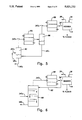
- FIG. 5 is a detailed process flow diagram showing another embodiment of the vapor-liquid equilibrium separation.
- FIG. 6 is a detailed process flow diagram showing yet another embodiment of the vapor-liquid equilibrium separation.
- a process feed gas stream having the foregoing composition may be received from natural gas cleanup processing at a temperature of 35° C. and a pressure substantially equal to atmospheric pressure.
- the Claus reaction may be performed at atmospheric pressure and the tail gas may be subsequently compressed to a pressure near the triple point pressure of carbon dioxide for crystallization processing or such other pressure as is required for pre-crystallization processing. If the feed gas is received at a high pressure, the Claus reaction may be performed at such pressure in order to minimize or eliminate downstream compression requirements.
- FIG. 1 a simplified process flow diagram for treatment of the process feed gas stream in a Claus process including tail gas cleanup in accordance with the present invention is shown.
- the major process steps or apparatus are schematically illustrated in FIG. 1 and include a sulfur recovery unit (SRU) 10 for producing and condensing elemental sulfur, a dehydrator 12 for removal of water from a tail gas from the SRU 10, an absorber 14 for separation of lower boiling constituents from sulfur-containing compounds, and a triple point crystallizer 16 for recovering and concentrating the sulfur-containing compounds in the feed to the SRU 10 by means of a recycle stream in line 18 and generating high purity liquid carbon dioxide absorbent as discussed below.
- SRU sulfur recovery unit
- the process feed stream in the line 20 is combined with the recycle stream in line 18 including unreacted or unconverted sulfur-containing compounds to produce a Claus feed stream flowing in line 22 to the SRU 10.
- the Claus feed stream contains about 80.3% sulfur-containing compounds on a molar basis.
- hydrogen sulfide is the only sulfur-containing compound present in a significant amount in the recycle stream in line 18 and it is present at about a 78.6% concentration.
- Other sulfur-containing compounds comprise about 1.7% sulfur dioxide and trace amounts of the above-noted additional contaminants.
- An oxidizing agent such as air or enriched air which is 95% oxygen and 5% nitrogen is added to the SRU 10 via line 19. Enriched air of the foregoing composition is used herein.
- the SRU 10 contains a single thermal reaction stage for converting the sulfur-containing compounds in the feed stream to elemental sulfur and a tail gas including unconverted sulfur-containing compounds.
- conversion to elemental sulfur will be in the range of 50-85% of the sulfur present in the Claus feed gas stream in line 22. (Of course, substantially 100% of the sulfur originally present in the process feed gas stream in line 20 is converted.)
- one or more catalytic reaction stages may be maintained, but such are not necessary to the Claus reaction process herein.
- the elemental sulfur is condensed and withdrawn from the SRU 10 through line 24.
- the Claus feed contains a stoichiometric excess of hydrogen sulfide.
- the formation of sulfur dioxide is thereby suppressed in accordance with the Claus reaction equilibrium equation: ##EQU1##
- the concentration of sulfur dioxide is reduced in accordance with the second power of the excess concentration of hydrogen sulfide.
- hydrogen sulfide will be the primary sulfur-containing compound in the tail gas since at least about 70% of the sulfur-containing compounds will be hydrogen sulfide.
- the sulfur-containing compounds in the tail gas may comprise up to about 99% hydrogen sulfide so that it is essentially the only sulfur-containing compound present.
- a tail gas containing about 48% of the sulfur originally present in the Claus feed gas in line 22 is withdrawn from the SRU 10 through line 26.
- the use of one or more additional reaction stages will tend to increase the percent of sulfur-containing compounds converted to sulfur as the gas flows through the SRU 10 and reduce the recycle stream flow. However, this is not necessary since essentially all of the sulfur-containing compounds in the tail gas are separated and recycled to the SRU 10 to enable recovery of 100% of the sulfur-containing compounds contained in the process feed gas stream in line 20. Accordingly, unless such additional stages are already present in a retro-fit application of the present invention, the use of the same is typically rejected based upon consideration of capital investment and operating energy costs.
- the use of a single stage in the SRU 10 also illustrates the application of the tail gas cleanup process to gas streams of relatively high sulfur content.
- the present tail gas cleanup process is not so limited. As indicated, the limitation is really determined by economics.
- the SRU 10 includes a cooling portion to condense the elemental sulfur formed in the Claus reaction.
- the condensed sulfur is withdrawn through line 24.
- Any elemental sulfur contained within the tail gas leaving the SRU 10 may be removed by conventional separation techniques. Such sulfur contaminant should be removed prior to dehydration of the tail gas in order to avoid a water and sulfur mixture which is difficult to handle.
- the tail gas from the SRU 10 may be hydrogenated prior to delivery to the dehydrator 12. This may be done in a known manner by passing the tail gas through a catalytic bed to convert any remaining sulfur dioxide and sulfur to hydrogen sulfide.
- the tail gas in the line 26 is delivered to dehydrator 12 for removal of water. Essentially, all of the water is separated and removed via line 28.
- the composition of the dehydrated tail gas withdrawn via line 30 is as follows.
- the nitrogen content is derived from the oxidizing agent and any nitrogen present in the process feed stream.
- the dehydrated tail gas is withdrawn from the dehydrator 12 through line 30 and passed to indirect heat exchanger 32 for cooling.
- the dehydrated tail gas is cooled in heat exchanger 32 to a temperature below its dew point to provide a gas/liquid mixture. For example, cooling to about -55° C. at a pressure of about 110 psia will provide a gas/liquid mixture which may be introduced into absorber 14 via line 34.
- liquid carbon dioxide absorbent delivered via line 36 absorbs sulfur-containing compounds from the upwardly flowing gaseous portion of the dehydrated tail gas. Accordingly, a purified tail gas essentially free of sulfur-containing compounds is withdrawn through line 38 from the absorber 14.
- the purified tail gas stream contains essentially only carbon dioxide and nitrogen. Less than one ppm of sulfur-containing compound in the purified tail gas stream is achieved easily in accordance with the disclosed process. Essentially 100% sulfur recovery can be achieved since all of the sulfur-containing compounds in the tail gas are absorbed by the liquid carbon dioxide and recycled to the Claus reaction. Accordingly, sulfur recovery is not restricted by Claus reaction thermodynamics or kinetics.
- the spent liquid carbon dioxide absorbent including absorbed sulfur-containing compounds is withdrawn from the absorber 14 through line 40 and introduced into the crystallizer 16 for purification.
- the liquid carbon dioxide and sulfur-containing compounds mixture provides the crystallizable liquid phase in the crystallizer.
- the sulfur-containing compounds are excluded from the solid phase formed upon freezing the liquid phase in the crystallizer 16 to produce the recycle stream in line 18.
- Purified liquid carbon dioxide is passed through line 36 to the absorber 14 for reuse.
- the absorber 14 may be eliminated and the dehydrated tail gas may be passed directly to the crystallizer 16 via lines 34 and 34(a), the latter being shown in dashed form in FIG. 1.
- Such a system also requires a pure oxygen oxidizing agent. Any excess carbon dioxide may be vented after its purification in the crystallizer 16. Any additional excess carbon dioxide not required in the absorption process may be withdrawn through line 36a as a liquid carbon dioxide product.
- triple point crystallization is preferred for subsequent purification of the spent absorbent and concentration of the recycle stream to be combined with the process feed stream.
- Triple point crystallization is applicable to the carbon dioxide and sulfur-containing compound mixture since such displays a unique pressure and temperature at which solid, liquid and gas phases coexist in equilibrium with each other in accordance with the conventional meaning of the term triple point.
- carbon dioxide is the crystallizable material and the sulfur-containing compounds are impurities or excluded materials.
- An in situ heat transfer material or component is also used. The cooling to form the solid phase is provided by evaporation of the in situ heat transfer component and the heating to melt the solid phase is provided by condensation of a vapor phase of the heat transfer component.
- the solid phase may be formed and melted at spaced zones located in the liquid phase.
- the solid phase is washed as it settles through the liquid phase intermediate the two zones.
- a condensing vapor is introduced into the melt zone for melting the submerged solid phase.
- a drained bed technique may be used wherein the solid phase is melted in a drained bed after separation from the liquid phase. The melt liquid drains through the bed without accumulation and the bed is substantially free of liquid during the melting step.
- a drained bed process is particularly described in assignee's U.S. Pat. No. 4,623,372.
- Each of the foregoing crystallization processes is a continuous separation cascade which operates mainly at temperatures and pressures near carbon dioxide triple point conditions. Small pressure differences through the cascade drive the process causing carbon dioxide to alternately freeze and melt at different locations in the cascade to establish concentration gradients and flows of crystallizable and excluded materials. Extremely pure carbon dioxide may be achieved by only a few stages of crystallization, e.g. 1 ppm of excluded material.
- stage 44 includes a flasher vessel 44a and associated washer-melter vessel 44b.
- stage 46 includes flasher vessel 46a and washer-melter vessel 46b.
- each washer-melter vessel a rising bed of carbon dioxide is formed and melted to provide a crystallizable material-enriched output which is withdrawn via lines 48 and 50, respectively.
- a stream of purified carbon dioxide is withdrawn from the washer-melter 44b through line 48 and passed to flasher 46a.
- a further purified stream of liquid carbon dioxide is withdrawn from the washer-melter 46b through line 50.
- a portion of the purified carbon dioxide in line 50 is vaporized in indirect heat exchanger 52 and returned via line 54 to the washer-melter 46b to provide a condensing vapor for further melting of the rising bed of carbon dioxide therein.
- the remaining portion of the purified liquid carbon dioxide withdrawn through line 50 provides a purified supply of absorbent passed via line 36 to the absorber 14.
- Evaporative cooling of the liquids in each of the flashers 44a and 46a produces a solid phase enriched in carbon dioxide.
- the solid phases are respectively delivered to the associated washer-melters as a slurry via lines 44c and 46c and inline pumps 58 and 60, respectively.
- the liquid phase or carrier fluids of the slurries are separated from the solid phases in each of the washer-melters 44b and 46b and returned to the associated flasher via lines 44d and 46d, respectively.
- the evaporative cooling in the flasher 46a produces an excluded material-enriched overhead vapor product withdrawn through line 62 and compressed by means of compressor 64 to provide a condensing vapor delivered via line 66 to the washer-melter 44b for melting the drained bed of carbon dioxide formed therein.
- This vapor flow also serves to upwardly convey the excluded sulfur-containing compounds to the adjacent higher stage 44.
- This upward flow may be supplemented by a liquid flow provided by passing a portion of the liquid flow in line 46d through line 46'd (shown in dotted outline) to line 44d and then to flasher 44a.
- Evaporative cooling in the flasher 44a produces an overhead vapor product having a high concentration of excluded material.
- the overhead product is withdrawn from the flasher 44a through line 68 and compressed by inline compressor 70.
- the overhead product is then passed via line 72 to indirect heat exchanger 74 wherein it is condensed and thereafter returned to the flasher 44a.
- heat exchangers 74 and 52 may comprise a single unit.
- the excluded material-enriched liquid withdrawn from washer-melter 44b is divided between line 44d and the recycle stream in line 18 including inline pump 42.
- the concentration of the excluded material or sulfur-containing compounds in this stream is approximately 78.6% hydrogen sulfide and 1.7% sulfur dioxide as indicated above. In this manner, a hydrogen sulfide-rich feed is maintained in the Claus reaction within the SRU 10.
- the in situ heat transfer component is primarily carbon dioxide with a lesser content of the excluded material.
- the pressure may be about 15 psia and the temperature -82° C. in the flasher 44a.
- the pressure will be in the order of 75 psia and the temperature about -57° C.
- FIG. 3 a simplified process flow diagram shows the sulfur recovery process of FIGS. 1 and 2 modified to include vapor-liquid equilibrium separation to produce a recycle stream of the desired composition, i.e. approximately 80% sulfur-containing compounds which primarily consist of hydrogen sulfide.
- the concentrating of the sulfur-containing compounds in the recycle stream is completed externally of the crystallizer. Accordingly, the recycle stream has a higher concentration of sulfur-containing compounds than exists at any location in the crystallization process.
- a vapor-liquid separator 80 receives a partially condensed flow of dehydrated tail gas from the heat exchanger 32 through line 34'a and an excluded material-enriched output from the crystallizer 16' through line 18'a which are separated into vapor and liquid phases.
- the liquid phase is withdrawn through line 18'b to provide a recycle flow of sulfur-containing compounds to the SRU 10.
- the vapor phase is withdrawn through line 34'b as a residual tail gas.
- the residual tail gas is cooled in indirect heat exchanger 82 to provide a vapor and liquid flow thereof for delivery to the absorber 14 through line 34'.
- the dehydrated tail gas is cooled to below its dew point in heat exchanger 32 (FIG. 3) to provide a vapor/liquid mixture at a temperature of about -30° C. and a pressure of 137 psia.
- the overall composition of the flow is about 65.4% hydrogen sulfide.
- the excluded material-enriched output from washer-melter 44b is delivered to the separator 80 via line 18'a as a liquid containing about 50% hydrogen sulfide at a temperature of -70° C. and a pressure of about 137 psia.
- the dehydrated tail gas and the excluded material-enriched output from the washer-melter are delivered to the separator 80 via line 34'a.
- the vapor and liquid components of the mixture of materials delivered via lines 34'a and 18'a are separated with the vapor phase being in equilibrium with the liquid phase.
- the liquid phase has a concentration of about 80% hydrogen sulfide and it is withdrawn through line 18'b and delivered to indirect heat exchanger 84 (FIG. 3) for heating and vaporization with recovery of its refrigeration energy.
- the vaporized liquid is then delivered through line 18' (FIG. 3) as a gaseous recycle stream to the SRU 10 (FIG. 3).
- the vapor phase is withdrawn from the separator 80 as a residual dehydrated tail gas containing about 40% hydrogen sulfide.
- the vapor is saturated and it is cooled in the heat exchanger 82 to provide a vapor/liquid mixture which is delivered through line 34' to the absorber 14.
- the liquid composition is about 50% hydrogen sulfide. Accordingly, the temperature is about -70° C. and the pressure is about 30 psia which correspond with the triple point conditions at such concentration of hydrogen sulfide. In contrast, the pressure in the flasher 44a (FIG. 2) in the process of FIGS. 1 and 2 is about 15 psia since the hydrogen sulfide concentration is about 80% therein. Accordingly, the vapor withdrawn through line 68 in the process of FIGS. 1 and 2 must be compressed an additional 15 psia by the compressor 70 (FIG. 2) since the triple point pressure is depressed by the increased hydrogen sulfide concentration.
- the use of the separator 80 to complete the concentration of the sulfur-containing compounds in the recycle stream externally of the crystallizer 16' thereby increases the minimum triple-point pressure therein and reduces the amount of compressor work required. Therefore, it is more energy and cost efficient in accordance with the embodiment of FIGS. 3 and 4 to utilize a vapor-liquid equilibrium separation in separator in 80 to concentrate the liquid phase to 80% hydrogen sulfide for recycle.
- a second vapor-liquid separator 86 may be connected in series with the separator 80 as shown in FIG. 5 with the use of the same reference numerals to identify corresponding parts described above in connection with the embodiments of FIGS. 1 to 4.
- the vapor phase withdrawn through line 34'b is condensed in part using indirect heat exchange in heat exchanger 82 for delivery as a vapor/liquid mixture to the separator 86.
- the vapor phase withdrawn through line 34'c from the separator 86 contains about 20% hydrogen sulfide.
- the vapor is condensed in part using indirect heat exchange in heat exchanger 88 and thereafter delivered via line 34' to the absorber 14.
- the liquid phase in separator 86 contains about 50% hydrogen sulfide.
- the liquid phase is passed via line 18'c to the separator 80.
- a distillation column 90 as shown in FIG. 6 may be used in place of series connected vapor-liquid separators 80 and 86.
- a three-tray column results in an overhead vapor removed via line 34'b.
- the vapor in line 34'b is condensed in heat exchanger 82.
- a portion of the condensed vapor is passed to the absorber 14 via line 34'.
- the remaining portion of the condensed vapor is returned via line 92 as a distillation recycle stream to the column 90.
- a liquid phase enriched in hydrogen sulfide is withdrawn from the bottom of the column via line 18'b for evaporation in heat exchanger 84 (FIG. 3) and recycled via line 18' to the SRU 10.
Landscapes
- Chemical & Material Sciences (AREA)
- Engineering & Computer Science (AREA)
- Chemical Kinetics & Catalysis (AREA)
- Organic Chemistry (AREA)
- Health & Medical Sciences (AREA)
- Biomedical Technology (AREA)
- Environmental & Geological Engineering (AREA)
- Analytical Chemistry (AREA)
- General Chemical & Material Sciences (AREA)
- Oil, Petroleum & Natural Gas (AREA)
- Inorganic Chemistry (AREA)
- Treating Waste Gases (AREA)
Abstract
Description
______________________________________
COMPONENT      MOL PERCENT
______________________________________
carbon dioxide 31.3%
hydrogen sulfide
               65.4%
sulfur dioxide  1.4%
nitrogen        1.9%
______________________________________
Claims (36)
Priority Applications (1)
| Application Number | Priority Date | Filing Date | Title |
|---|---|---|---|
| US07/415,100 US5021232A (en) | 1989-09-29 | 1989-09-29 | Sulfur recovery process |
Applications Claiming Priority (1)
| Application Number | Priority Date | Filing Date | Title |
|---|---|---|---|
| US07/415,100 US5021232A (en) | 1989-09-29 | 1989-09-29 | Sulfur recovery process |
Publications (1)
| Publication Number | Publication Date |
|---|---|
| US5021232A true US5021232A (en) | 1991-06-04 |
Family
ID=23644383
Family Applications (1)
| Application Number | Title | Priority Date | Filing Date |
|---|---|---|---|
| US07/415,100 Expired - Fee Related US5021232A (en) | 1989-09-29 | 1989-09-29 | Sulfur recovery process |
Country Status (1)
| Country | Link |
|---|---|
| US (1) | US5021232A (en) |
Cited By (13)
| Publication number | Priority date | Publication date | Assignee | Title |
|---|---|---|---|---|
| US20050258087A1 (en) * | 2002-06-25 | 2005-11-24 | Lalit Chordia | Novel collection system for chromatographic system |
| US20050287056A1 (en) * | 2004-06-29 | 2005-12-29 | Dakota Gasification Company | Removal of methyl mercaptan from gas streams |
| US20060260189A1 (en) * | 2003-04-03 | 2006-11-23 | Fluor Corporation | Configurations and methods of carbon capture |
| US7250149B1 (en) | 2004-02-24 | 2007-07-31 | Smith Strom W | Sulfur gas treatment process |
| WO2008042788A2 (en) * | 2006-09-29 | 2008-04-10 | Uop Llc | Integrated separation and purification process |
| US20080107581A1 (en) * | 2004-07-12 | 2008-05-08 | Exxonmobil Upstream Research Company | Methods for Removing Sulfur-Containing Compounds |
| US20080190291A1 (en) * | 2007-02-13 | 2008-08-14 | Drew Linden Krehbiel | Method and apparatus for sub-sea processing |
| US20100111824A1 (en) * | 2006-09-26 | 2010-05-06 | Lurgi Gmbh | Hydrogen production method |
| DE102010006102A1 (en) * | 2010-01-28 | 2011-08-18 | Siemens Aktiengesellschaft, 80333 | Process for the separation of purified value gas from a gas mixture, and apparatus for carrying out this process |
| US10005666B2 (en) * | 2016-01-05 | 2018-06-26 | Saudi Arabian Oil Company | Claus process for sulfur recovery with intermediate water vapor removal by adsorption |
| US10793434B2 (en) | 2019-01-25 | 2020-10-06 | Strom W. Smith | System for hydrogen sulfide destruction and sulfur recovery |
| US10968151B1 (en) | 2019-09-27 | 2021-04-06 | Wm Intellectual Property Holdings, L.L.C. | System and process for recovering methane and carbon dioxide from biogas and reducing greenhouse gas emissions |
| CN114195102A (en) * | 2021-12-28 | 2022-03-18 | 武汉国力通能源环保股份有限公司 | Method and device for refining sulfur from desulfurized sulfur paste |
Citations (9)
| Publication number | Priority date | Publication date | Assignee | Title |
|---|---|---|---|---|
| US4153674A (en) * | 1976-12-07 | 1979-05-08 | Shell Oil Company | Sulfur recovery from gases rich in H2 S and CO2 as well as COS or organic sulfur |
| US4169133A (en) * | 1977-02-08 | 1979-09-25 | Krupp-Koppers Gmbh | Process for recovering acidic gases collected during gas desulfurization |
| US4263270A (en) * | 1976-03-08 | 1981-04-21 | Shell Oil Company | Process for working-up hydrogen sulphide-containing gases |
| US4270937A (en) * | 1976-12-01 | 1981-06-02 | Cng Research Company | Gas separation process |
| US4406873A (en) * | 1980-10-20 | 1983-09-27 | The Ralph M. Parsons Co. | Process for sulfur production |
| US4581052A (en) * | 1976-12-01 | 1986-04-08 | Cng Research Company | Gas separation process |
| US4609388A (en) * | 1979-04-18 | 1986-09-02 | Cng Research Company | Gas separation process |
| US4620967A (en) * | 1983-03-29 | 1986-11-04 | Firma Carl Still Gmbh & Co. Kg | Method of recovering sulfur in a Claus process from vapors obtained in coke oven gas cleaning |
| US4623372A (en) * | 1984-07-11 | 1986-11-18 | Cng Research Company | Crystallization process |
-
1989
- 1989-09-29 US US07/415,100 patent/US5021232A/en not_active Expired - Fee Related
Patent Citations (9)
| Publication number | Priority date | Publication date | Assignee | Title |
|---|---|---|---|---|
| US4263270A (en) * | 1976-03-08 | 1981-04-21 | Shell Oil Company | Process for working-up hydrogen sulphide-containing gases |
| US4270937A (en) * | 1976-12-01 | 1981-06-02 | Cng Research Company | Gas separation process |
| US4581052A (en) * | 1976-12-01 | 1986-04-08 | Cng Research Company | Gas separation process |
| US4153674A (en) * | 1976-12-07 | 1979-05-08 | Shell Oil Company | Sulfur recovery from gases rich in H2 S and CO2 as well as COS or organic sulfur |
| US4169133A (en) * | 1977-02-08 | 1979-09-25 | Krupp-Koppers Gmbh | Process for recovering acidic gases collected during gas desulfurization |
| US4609388A (en) * | 1979-04-18 | 1986-09-02 | Cng Research Company | Gas separation process |
| US4406873A (en) * | 1980-10-20 | 1983-09-27 | The Ralph M. Parsons Co. | Process for sulfur production |
| US4620967A (en) * | 1983-03-29 | 1986-11-04 | Firma Carl Still Gmbh & Co. Kg | Method of recovering sulfur in a Claus process from vapors obtained in coke oven gas cleaning |
| US4623372A (en) * | 1984-07-11 | 1986-11-18 | Cng Research Company | Crystallization process |
Cited By (23)
| Publication number | Priority date | Publication date | Assignee | Title |
|---|---|---|---|---|
| US20050258087A1 (en) * | 2002-06-25 | 2005-11-24 | Lalit Chordia | Novel collection system for chromatographic system |
| US20060260189A1 (en) * | 2003-04-03 | 2006-11-23 | Fluor Corporation | Configurations and methods of carbon capture |
| US7250149B1 (en) | 2004-02-24 | 2007-07-31 | Smith Strom W | Sulfur gas treatment process |
| US20050287056A1 (en) * | 2004-06-29 | 2005-12-29 | Dakota Gasification Company | Removal of methyl mercaptan from gas streams |
| US7662215B2 (en) | 2004-07-12 | 2010-02-16 | Exxonmobil Upstream Research Company | Methods for removing sulfur-containing compounds |
| US20080107581A1 (en) * | 2004-07-12 | 2008-05-08 | Exxonmobil Upstream Research Company | Methods for Removing Sulfur-Containing Compounds |
| US8273323B2 (en) * | 2006-09-26 | 2012-09-25 | Lurgi Gmbh | Hydrogen production method |
| US20100111824A1 (en) * | 2006-09-26 | 2010-05-06 | Lurgi Gmbh | Hydrogen production method |
| WO2008042788A2 (en) * | 2006-09-29 | 2008-04-10 | Uop Llc | Integrated separation and purification process |
| US7637984B2 (en) | 2006-09-29 | 2009-12-29 | Uop Llc | Integrated separation and purification process |
| WO2008042788A3 (en) * | 2006-09-29 | 2008-06-19 | Uop Llc | Integrated separation and purification process |
| WO2008100408A2 (en) * | 2007-02-13 | 2008-08-21 | Kellogg Brown & Root Llc | Method and apparatus for sub-sea processing |
| US7770651B2 (en) * | 2007-02-13 | 2010-08-10 | Kellogg Brown & Root Llc | Method and apparatus for sub-sea processing |
| WO2008100408A3 (en) * | 2007-02-13 | 2008-11-13 | Kellogg Brown & Root Llc | Method and apparatus for sub-sea processing |
| US20080190291A1 (en) * | 2007-02-13 | 2008-08-14 | Drew Linden Krehbiel | Method and apparatus for sub-sea processing |
| DE102010006102A1 (en) * | 2010-01-28 | 2011-08-18 | Siemens Aktiengesellschaft, 80333 | Process for the separation of purified value gas from a gas mixture, and apparatus for carrying out this process |
| US10005666B2 (en) * | 2016-01-05 | 2018-06-26 | Saudi Arabian Oil Company | Claus process for sulfur recovery with intermediate water vapor removal by adsorption |
| US10793434B2 (en) | 2019-01-25 | 2020-10-06 | Strom W. Smith | System for hydrogen sulfide destruction and sulfur recovery |
| US10968151B1 (en) | 2019-09-27 | 2021-04-06 | Wm Intellectual Property Holdings, L.L.C. | System and process for recovering methane and carbon dioxide from biogas and reducing greenhouse gas emissions |
| US11220470B2 (en) | 2019-09-27 | 2022-01-11 | Wm Intellectual Property Holdings, L.L.C. | System and process for recovering methane and carbon dioxide from biogas and reducing greenhouse gas emissions |
| US11708313B2 (en) | 2019-09-27 | 2023-07-25 | Wm Intellectual Property Holdings, L.L.C. | System and process for recovering methane and carbon dioxide from biogas and reducing greenhouse gas emissions |
| CN114195102A (en) * | 2021-12-28 | 2022-03-18 | 武汉国力通能源环保股份有限公司 | Method and device for refining sulfur from desulfurized sulfur paste |
| CN114195102B (en) * | 2021-12-28 | 2024-01-12 | 武汉国力通能源环保股份有限公司 | Method and device for refining sulfur from desulfurization sulfur paste |
Similar Documents
| Publication | Publication Date | Title |
|---|---|---|
| EP0212297B1 (en) | High pressure process for sulfur recovery from a hydrogen sulfide containing gas stream | |
| US5304361A (en) | Removal of hydrogen sulfide | |
| US4430316A (en) | Scrubbing system yielding high concentration of hydrogen sulfide | |
| US5733516A (en) | Process for removal of hydrogen sulfide from a gas stream | |
| US5021232A (en) | Sulfur recovery process | |
| US3335071A (en) | Ammonia recovery process | |
| US4124685A (en) | Method for substantially complete removal of hydrogen sulfide from sulfur bearing industrial gases | |
| EP0066306B1 (en) | process for the removal of h2s and co2 from gaseous streams | |
| EP0215505A2 (en) | Removing H2S from a sour gaseous stream | |
| US3971844A (en) | Method for removing sodium sulfate from aqueous solutions | |
| US4412977A (en) | Selective acid gas removal | |
| US3365374A (en) | H2s recovery by absorption and plural distillation | |
| EP0189558A2 (en) | Oxidative removal of hydrogen sulfide from gas streams | |
| EP1456123B1 (en) | Method of recovering sulfurous components in a sulfur-recovery process | |
| US4110087A (en) | Sulfur dioxide removal by absorption and fractionation | |
| EP0186235B1 (en) | Removal of acid gases from a sour gaseous stream | |
| US20070006731A1 (en) | Method for removing acid gases from pressurized natural gas that is contaminated with acid gas compounds and recovering the removed acid gases at an increased pressure level | |
| CS196350B2 (en) | Treatnment of gases containing hydrogen sulphide | |
| US5951961A (en) | Process for treating a gas containing hydrogen sulphide and sulphur dioxide, comprising a step for eliminating sulphur by cooling a gaseous effluent | |
| US4530827A (en) | Process for the simultaneous removal of H2 S, SO2 and elemental sulfur from gaseous mixtures | |
| KR19990022865A (en) | Method and apparatus for treating hydrogen sulfide-containing gas comprising a cooling step for crystallizing and removing sulfur | |
| EP0151010B1 (en) | Apparatus and process for the concentration of sulphuric acid | |
| JPS6097028A (en) | Treatment of exhaust gas | |
| US4123505A (en) | Reducing SO2 in refinery off gas | |
| EP0375077B1 (en) | Removing hydrogen sulphide from a gas mixture |
Legal Events
| Date | Code | Title | Description |
|---|---|---|---|
| AS | Assignment |
Owner name: CNG RESEARCH COMPANY, A CORP. OF DE Free format text: ASSIGNMENT OF ASSIGNORS INTEREST.;ASSIGNORS:HISE, RALPH E.;COOK, W. JEFFREY;REEL/FRAME:005147/0687 Effective date: 19890929 |
|
| FEPP | Fee payment procedure |
Free format text: PAYOR NUMBER ASSIGNED (ORIGINAL EVENT CODE: ASPN); ENTITY STATUS OF PATENT OWNER: SMALL ENTITY |
|
| FPAY | Fee payment |
Year of fee payment: 4 |
|
| FEPP | Fee payment procedure |
Free format text: PAT HOLDER CLAIMS SMALL ENTITY STATUS - SMALL BUSINESS (ORIGINAL EVENT CODE: SM02); ENTITY STATUS OF PATENT OWNER: SMALL ENTITY |
|
| AS | Assignment |
Owner name: ACRION TECHNOLOGIES, INC., OHIO Free format text: ASSIGNMENT OF ASSIGNORS INTEREST;ASSIGNOR:CNG RESEARCH COMPANY;REEL/FRAME:007779/0922 Effective date: 19951228 |
|
| REMI | Maintenance fee reminder mailed | ||
| LAPS | Lapse for failure to pay maintenance fees | ||
| FP | Lapsed due to failure to pay maintenance fee |
Effective date: 19990604 |
|
| STCH | Information on status: patent discontinuation |
Free format text: PATENT EXPIRED DUE TO NONPAYMENT OF MAINTENANCE FEES UNDER 37 CFR 1.362 |