US5025969A - Dual actuation staple insertion apparatus - Google Patents
Dual actuation staple insertion apparatus Download PDFInfo
- Publication number
- US5025969A US5025969A US07/232,151 US23215188A US5025969A US 5025969 A US5025969 A US 5025969A US 23215188 A US23215188 A US 23215188A US 5025969 A US5025969 A US 5025969A
- Authority
- US
- United States
- Prior art keywords
- staple
- chamber
- secured
- drive means
- open end
- Prior art date
- Legal status (The legal status is an assumption and is not a legal conclusion. Google has not performed a legal analysis and makes no representation as to the accuracy of the status listed.)
- Expired - Fee Related
Links
Images


Classifications
-
- B—PERFORMING OPERATIONS; TRANSPORTING
- B25—HAND TOOLS; PORTABLE POWER-DRIVEN TOOLS; MANIPULATORS
- B25C—HAND-HELD NAILING OR STAPLING TOOLS; MANUALLY OPERATED PORTABLE STAPLING TOOLS
- B25C5/00—Manually operated portable stapling tools; Hand-held power-operated stapling tools; Staple feeding devices therefor
- B25C5/10—Driving means
- B25C5/11—Driving means operated by manual or foot power
Definitions
- This invention relates to staple insertion apparatus, and more particularly to an apparatus for sequentially inserting large, generally U-shaped staples through agricultural mats, erosion control mats, or other sheet like material, into the ground, by manual force generated by the user's hands, foot or a combination of hand and foot actuation.
- mat or sheet materials may incorporate seeds, fertilizers, or various forms of week control to improve growing conditions.
- Mat or sheet material may be employed to control soil erosion. The mat or sheet material is tailored to follow the uneven contour of the ground.
- U.S. Pat. No. 4,706,864 discloses a fastener implanting machine actuated by foot pressure wherein a spring extends over a pulley to raise the driver when the operator is not exerting foot pressure on the foot pedal.
- the fasteners disclosed are not U-shaped fasteners, but utilize a shorter leg and a longer leg: or two shorter legs and a centrally disposed longer leg.
- U.S. Pat. No. 4,377,919 discloses a hold down system for horticultural plastic sheet, which employs "T", “L” or inverted “W” shaped fasteners, which are manually positioned and inserted into the ground with a driving tool utilizing a combination of foot and hand power.
- U.S. Pat. No. 3,890,910 discloses an air powered staple insertion apparatus, actuated by a foot valve, to pneumatically drive the staple into the ground.
- the staple insertion apparatus disclosed herein utilizes the manual force of the operator's hands, or the operator's foot, or a combination of the operator's hands and foot, to drive a large U-shaped staple through a mat or sheet, into the ground to secure and retain the material against the ground.
- the U-shaped staples are preferably secured together in an aligned, juxtaposed relation for ease of handling and insertion of a plurality of staples into the staple insertion chamber.
- the operator positions the apparatus upon the mat or sheet material, and utilizes hand or foot pressure, or both, to bias the drive member against the forward most staple positioned beneath the drive member, into the ground.
- a spring member raises the drive member into a first operating position, whereupon the plurality of staples in the chamber are biased to align the next adjacent staple beneath the drive member in preparation for the next staple insertion.
- a chamber protects the staples during use, by enclosing the staples between the top, bottom and sides of the housing.
- FIG. 1 shows a perspective view of the staple insertion apparatus, with the staple advancing means and a plurality of staples shown in exploded view.
- FIG. 2 is a cross sectional view of the staple insertion apparatus, with the staple advancing apparatus releasably secured within the housing.
- FIG. 3 is a cross sectional view of the housing, taken along lines 3--3 in FIG. 2.
- FIG. 4 is an end view of the staple insertion apparatus, with the drive member positioned in the lower operating position.
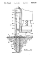
- FIG. 1 shows the staple insertion apparatus 10, positioned upon a large portion of selected material 12. Operator 13 grasps handle 15 in preparation for insertion of a staple 14 through the selected material 12, into the ground (not shown).
- a plurality of staples 14 are shown in exploded view, in aligned, juxtaposed relation.
- staples 14 are preferably secured together by one or more traverse strips 22 secured to each staple 14.
- the ends 24 of each staple 14 are preferably pointed to aid insertion of staple 14 into the ground.
- Each staple 14 may be formed from wire, strip, or sheet material into a generally U-shaped configuration having a top portion 26, with depending side portions 18, 20. The adjoining top 26 and side portions 18, 20 of each staple 14 are preferably radiused to avoid stress concentration during insertion.
- the staple insertion apparatus 10 of FIG. 1-4 comprises an elongated, horizontally disposed housing 30 having a bottom portion 82, opposing side portions 34, 36 adjacent to the bottom portion 32, and a top portion 38 adjacent to the side portions 34, 36 forming a chamber 40 therebetween.
- Chamber 40 is sized to slidably receive a plurality of staples 14 therein.
- the opposing ends of chamber 40 form a first open end portion 42 and a second open end portion 44.
- the plurality of staples 14 are inserted through second open end portion 44, and are biased by staple advancing means 50 towards the first open end portion 42.
- the staple advancing means 50 preferably comprises a tubular handle portion 52 extending externally from an end closure member 54 having an aperture 56 therethrough.
- An elongated rod 58 is secured at one end in spaced relation within tubular handle portion 52, and extends in spaced relation through aperture 56 in closure member 54.
- elongated rod 58 is sized to extend substantially the length of chamber 40, as shown in FIG. 3.
- Staple guide means 62 is sized to be slidably received within chamber 40, and to abut the staple 14 closest to the second open end portion 44.
- staple guide means 62 preferably comprises a top portion 64, and adjoining side portions 66, 68.
- a central extension 70 depends from top portion 64 in spaced relation between side portions 66, 68 to support a boss 72 having an aperture 74 therethrough.
- Rod 58 is slidably disposed through aperture 74 in staple guide means 62, and a biasing means 76, such as a compression spring, preferably extends about rod 58 between staple guide means 62 and tubular handle 52.
- Tubular handle 52 is sized to substantially receive biasing means 76 therein when chamber 40 is fully loaded with a plurality of staples 14.
- Biasing means 76 is sized to linearly bias staple guide means 62 substantially towards the first open end portion 42 of chamber 40 in a manner to sequentially align each of the plurality of staples 14 disposed within chamber 40 in proximity to first open end portion 42.
- a retaining means 78 is preferably secured at end 80 of rod 58 to retain staple guide means on rod 58 when the staple advancing means 50 is removed from chamber 40 as shown in FIG. 1.
- staple support member 82 is secured to the bottom 32 of housing 30 within chamber 40 in spaced relation from top 88 and sides 84, 36.
- staple support member 82 extends substantially the length of chamber 40 to support staples 14 as they are biased by the staple advancing means 50 towards first open end 42.
- Staple support member 82 is preferably formed with sides 84, 86 extending in spaced relation from sides 34, 36 of housing 30, with upper ends 88, 90 inclined towards each other in spaced relation in a manner to support the top portion 26 of staples 14. This allows staples of various lengths to be utilized without adversely affecting the actuation of staple insertion apparatus 10.
- the space 92 between upper ends 88, 90 allows central extension 70 of staple guide means 62 to be slidably received therebetween.
- Staple guide means 62 is supported upon ends 88. 90 of staple support member 82 which serves to align staple guide means 62 in relation to the plurality of staples 14, regardless of staple length.
- a housing support member 94 is secured to housing 30 in proximity to the first open end portion 42.
- Housing support member 94 is preferably secured to housing 80 in proximity to the first open end portion 42.
- Housing support member 94 may be fabricated of one or more pieces, and extends above housing 30 to secure a vertically disposed tubular member 96 in spaced relation above the first open end portion 42 of chamber 40.
- a staple retaining means 97, 98 serves to limit the travel of staples 14 in a manner to align the staple 14 closest to the first open end portion 42 beneath the staple drive member 100.
- Staple drive member 100 is sized to be slidably received between staple retaining means 97, 98 and the first open end portion 42 of chamber 40.
- the bottom portion of drive member 100 is contoured to the general configuration of the top portion 26 of each staple 14.
- Staple retaining means 97, 98 may be secured to housing 30, or to housing support member 94 in accordance with manufacturing preference.
- housing support member 94 is formed to the configuration of staple retaining means 97, 98.
- Staple drive member 100 is secured to an elongated drive member 102.
- Elongated drive member 102 is slidably received within tubular member 96, and extends above tubular member 96, as best shown in FIG. 2.
- a foot actuation member 104 may be secured to the elongated drive member 102 at a location below tubular member 96. Foot actuation member 104 is preferably releasably secured to elongated drive member 102 to allow alternate positioning of the foot actuation member 104 for use from the operator's left or right side, according to the operator's preference.
- a first biasing means 106 is slidably disposed upon elongated drive member 102, between the upper end 107 of tubular member 96 and a stop 109.
- Stop 109 is secured to elongated drive member 102 to allow drive member 102 to be biased between an upper operating position where the drive member 102 is above the first open end portion of chamber 40, and a lower operating position where the driVe member 102 is extended substantially across the first open end portion of chamber 40.
- the stop 109 is preferably secured to drive member 102 in a manner to restrict the staple drive member 100 from extending substantially below the bottom 32 of housing 30, as best shown in FIG. 4.
- Handles 122, 123 are preferably secured to drive member 102 above stop 109, at right angles to drive member 102. Handles 122, 123 preferably extend from each side of the elongated drive member 102 to provide opposed gripping surfaces on opposite sides of the elongated drive member 102. The opposed handles 122. 123 center the downward force applied upon the handles by the operator about the drive member 102.
- the first biasing means 106 acts against the upper end 97 of tubular member 96 and stop 109 to raise drive member 102 to the upper operating position, in preparation for insertion of the next staple 14.
- the elongated drive member 102 is linearly biased towards the ground.
- the downward force drives the staple drive member 100 against the top portion of the staple 14 aligned beneath the staple drive member 100, forcibly separating staple 14 from the remaining staples disposed upon staple support member 82, to forcibly drive the separated staple 14 through the selected material 12, into the ground.
- the first biasing member 106 As staple 14 is driven into the ground, the first biasing member 106 is compressed. Upon completion of the downward force applied by the operator, the biasing member 106 expands to raise the drive member 102 to the upper operating position shown in FIG. 1 and 2.
- a cap 120 may be secured to the upper end of elongated drive member 102 to stop foreign material from entering into elongated drive member 102. Likewise, the bottom portion of elongated drive member 102 may be plugged, or otherwise closed off to stop foreign material from entering elongated drive member 102.
- Staple support member 82 may also be closed off in proximity to end 42 of chamber 40. However, the space between sides 84, 86 of staple support member 82 and sides 34, 36 of chamber 40 must remain sufficiently open to allow passage of staple 14 closest to end 42 to abut staple retaining means 97, 98 in order to properly align staple 14 beneath staple drive member 100, when the drive member 102 is raised into the upper operating position.
- Operator 13 may easily move and reposition the staple insertion apparatus 10 with handles 122, 123 in preparation for insertion of the next staple 14.
- the operator 13 may drive the staple 14 into the ground.
- the first biasing means 106 raises the elongated drive member 102, which also raises staple drive member 100, foot actuation member 104, stop 109 and handles 122, 123, in preparation for subsequent staple insertion.
- the operator 13 may then move several strides to the next staple insertion location and repeat the staple insertion procedure, to sequentially insert each of a plurality of staples disposed within chamber 40 through material 12, thereby covering a great expanse of material 12, in a very short time.
- operator 18 may quickly reload the next plurality of staples within chamber 40 by releasing retaining means 60 and withdrawing staple advancing means 50 from chamber 40.
- Operator 13 may then load the next plurality of staples 14 within chamber 40 and insert staple advancing means 50 into chamber 40 to bias staples 14 towards the first open end portion 42 of chamber 40.
- Staple advancing means 50 is then secured to housing 30 with retaining means 60, in preparation for further use.
Abstract
Description
Claims (20)
Priority Applications (1)
| Application Number | Priority Date | Filing Date | Title |
|---|---|---|---|
| US07/232,151 US5025969A (en) | 1987-05-11 | 1988-08-15 | Dual actuation staple insertion apparatus |
Applications Claiming Priority (2)
| Application Number | Priority Date | Filing Date | Title |
|---|---|---|---|
| US07/048,739 US4826066A (en) | 1987-05-11 | 1987-05-11 | Staple insertion apparatus |
| US07/232,151 US5025969A (en) | 1987-05-11 | 1988-08-15 | Dual actuation staple insertion apparatus |
Related Parent Applications (1)
| Application Number | Title | Priority Date | Filing Date |
|---|---|---|---|
| US07/048,739 Continuation-In-Part US4826066A (en) | 1987-05-11 | 1987-05-11 | Staple insertion apparatus |
Publications (1)
| Publication Number | Publication Date |
|---|---|
| US5025969A true US5025969A (en) | 1991-06-25 |
Family
ID=26726481
Family Applications (1)
| Application Number | Title | Priority Date | Filing Date |
|---|---|---|---|
| US07/232,151 Expired - Fee Related US5025969A (en) | 1987-05-11 | 1988-08-15 | Dual actuation staple insertion apparatus |
Country Status (1)
| Country | Link |
|---|---|
| US (1) | US5025969A (en) |
Cited By (23)
| Publication number | Priority date | Publication date | Assignee | Title |
|---|---|---|---|---|
| US5211722A (en) * | 1989-08-01 | 1993-05-18 | Wagner John W | Divot anchoring process |
| US6053260A (en) * | 1998-06-23 | 2000-04-25 | Boon; Peter | Flagger/marker/locator |
| US6142352A (en) * | 1998-05-05 | 2000-11-07 | Illinois Tool Works Inc. | Roofing washer-dispensing and fastener-driving machine |
| US6585456B2 (en) | 2001-03-21 | 2003-07-01 | Johnston-Morehouse-Dickey, Co. | Combination anchoring pin and insertion apparatus |
| US20040011847A1 (en) * | 2002-07-22 | 2004-01-22 | Wells Joe F. | Fastener insertion device |
| US20040258480A1 (en) * | 2003-06-19 | 2004-12-23 | Prisby James V. | Conduit installation tool and method of use thereof |
| US20060062680A1 (en) * | 2004-08-31 | 2006-03-23 | Mark Myrowich | Turf stapler |
| US20080105726A1 (en) * | 2006-10-18 | 2008-05-08 | Malco Products, Inc. | Vertical feed hand stapler |
| US7476059B1 (en) | 2006-11-20 | 2009-01-13 | Gregory Paul Holland | Erosion control and stabilization blanket stapling apparatus |
| US20100276468A1 (en) * | 2009-05-04 | 2010-11-04 | Carrette Paul M | Marker system with marker and installation apparatus |
| WO2011041825A1 (en) | 2009-10-05 | 2011-04-14 | Christopher John Lacy | Apparatus and methods for inserting a fastener |
| US7992754B1 (en) * | 2009-05-04 | 2011-08-09 | Flagshooter, LLC | Marker system with marker and installation apparatus |
| US20110197804A1 (en) * | 2009-05-04 | 2011-08-18 | Flag Shooter, Llc | Marker Apparatus |
| US20110210154A1 (en) * | 2009-05-04 | 2011-09-01 | Flag Shooter, Llc | Marker Installation Apparatus |
| US20120012635A1 (en) * | 2010-07-16 | 2012-01-19 | Barry Jaffe | Stapler for preventing simultaneous dispensing of multiple staples |
| US8136471B1 (en) | 2009-05-04 | 2012-03-20 | Flagshooter, LLC | Marker system with marker and installation apparatus |
| EP2604391A1 (en) * | 2011-12-15 | 2013-06-19 | Roth Werke GmbH | Device for storing and providing tube holders for fixing tubes |
| US20130334276A1 (en) * | 2012-06-13 | 2013-12-19 | James C. McDonald | Utility marker setter |
| US20140048579A1 (en) * | 2012-08-14 | 2014-02-20 | Patrick Thompson | Location marking device |
| US20150217437A1 (en) * | 2014-02-05 | 2015-08-06 | Mark Howard Thomaschefsky | Sod Staple Inserter |
| US20170317479A1 (en) * | 2016-05-02 | 2017-11-02 | Lg Electronics Inc. | Wire installation apparatus and control method thereof |
| CN109664244A (en) * | 2018-12-29 | 2019-04-23 | 湖南达道新能源开发有限公司 | A kind of nail pipe machine |
| US10688643B2 (en) | 2016-03-25 | 2020-06-23 | Source All Media, Inc | Staple insertion device |
Citations (8)
| Publication number | Priority date | Publication date | Assignee | Title |
|---|---|---|---|---|
| US1441474A (en) * | 1922-04-08 | 1923-01-09 | Andrew M Anderson | Stapling machine |
| US1919944A (en) * | 1931-11-19 | 1933-07-25 | Acme Staple Company | Stapie setting machine |
| US3035269A (en) * | 1961-06-09 | 1962-05-22 | Latsch William | Portable driver for fasteners |
| US3890910A (en) * | 1972-04-19 | 1975-06-24 | Bunzl & Biach Ag | Method of laying webs of composite material containing plant seed |
| US4139136A (en) * | 1977-07-25 | 1979-02-13 | Catalano Joseph R | Nail driver |
| US4377919A (en) * | 1981-10-26 | 1983-03-29 | Gams Joseph W | Holddown system for horticultural plastic sheet |
| US4627563A (en) * | 1985-08-20 | 1986-12-09 | Meyer Dennis W | Device for driving U-shaped anchors into the ground |
| US4706864A (en) * | 1986-02-28 | 1987-11-17 | William M. Jacobsen | Fastener implanting machine for ground erosion covers |
-
1988
- 1988-08-15 US US07/232,151 patent/US5025969A/en not_active Expired - Fee Related
Patent Citations (8)
| Publication number | Priority date | Publication date | Assignee | Title |
|---|---|---|---|---|
| US1441474A (en) * | 1922-04-08 | 1923-01-09 | Andrew M Anderson | Stapling machine |
| US1919944A (en) * | 1931-11-19 | 1933-07-25 | Acme Staple Company | Stapie setting machine |
| US3035269A (en) * | 1961-06-09 | 1962-05-22 | Latsch William | Portable driver for fasteners |
| US3890910A (en) * | 1972-04-19 | 1975-06-24 | Bunzl & Biach Ag | Method of laying webs of composite material containing plant seed |
| US4139136A (en) * | 1977-07-25 | 1979-02-13 | Catalano Joseph R | Nail driver |
| US4377919A (en) * | 1981-10-26 | 1983-03-29 | Gams Joseph W | Holddown system for horticultural plastic sheet |
| US4627563A (en) * | 1985-08-20 | 1986-12-09 | Meyer Dennis W | Device for driving U-shaped anchors into the ground |
| US4706864A (en) * | 1986-02-28 | 1987-11-17 | William M. Jacobsen | Fastener implanting machine for ground erosion covers |
Cited By (33)
| Publication number | Priority date | Publication date | Assignee | Title |
|---|---|---|---|---|
| US5211722A (en) * | 1989-08-01 | 1993-05-18 | Wagner John W | Divot anchoring process |
| US6142352A (en) * | 1998-05-05 | 2000-11-07 | Illinois Tool Works Inc. | Roofing washer-dispensing and fastener-driving machine |
| US6053260A (en) * | 1998-06-23 | 2000-04-25 | Boon; Peter | Flagger/marker/locator |
| US6585456B2 (en) | 2001-03-21 | 2003-07-01 | Johnston-Morehouse-Dickey, Co. | Combination anchoring pin and insertion apparatus |
| US20040011847A1 (en) * | 2002-07-22 | 2004-01-22 | Wells Joe F. | Fastener insertion device |
| US6926186B2 (en) | 2002-07-22 | 2005-08-09 | North American Green, Inc. | Fastener insertion device |
| US20040258480A1 (en) * | 2003-06-19 | 2004-12-23 | Prisby James V. | Conduit installation tool and method of use thereof |
| US20060062680A1 (en) * | 2004-08-31 | 2006-03-23 | Mark Myrowich | Turf stapler |
| US20080105726A1 (en) * | 2006-10-18 | 2008-05-08 | Malco Products, Inc. | Vertical feed hand stapler |
| US7476059B1 (en) | 2006-11-20 | 2009-01-13 | Gregory Paul Holland | Erosion control and stabilization blanket stapling apparatus |
| US20100276468A1 (en) * | 2009-05-04 | 2010-11-04 | Carrette Paul M | Marker system with marker and installation apparatus |
| US7992754B1 (en) * | 2009-05-04 | 2011-08-09 | Flagshooter, LLC | Marker system with marker and installation apparatus |
| US20110197804A1 (en) * | 2009-05-04 | 2011-08-18 | Flag Shooter, Llc | Marker Apparatus |
| US20110210154A1 (en) * | 2009-05-04 | 2011-09-01 | Flag Shooter, Llc | Marker Installation Apparatus |
| US8065856B2 (en) * | 2009-05-04 | 2011-11-29 | Flagshooter, LLC | Marker system with marker and installation apparatus |
| US8656857B2 (en) * | 2009-05-04 | 2014-02-25 | Flagshooter Holdings, Llc | Marker installation apparatus |
| US8136471B1 (en) | 2009-05-04 | 2012-03-20 | Flagshooter, LLC | Marker system with marker and installation apparatus |
| WO2011041825A1 (en) | 2009-10-05 | 2011-04-14 | Christopher John Lacy | Apparatus and methods for inserting a fastener |
| EP2485872A1 (en) * | 2009-10-05 | 2012-08-15 | Christopher John Lacy | Apparatus and methods for inserting a fastener |
| CN102712082A (en) * | 2009-10-05 | 2012-10-03 | 克里斯托弗·约翰·拉丝 | Apparatus and methods for inserting a fastener |
| US20120261456A1 (en) * | 2009-10-05 | 2012-10-18 | Christopher John Lacy | Apparatus and methods for inserting a fastener |
| CN102712082B (en) * | 2009-10-05 | 2016-03-16 | 克里斯托弗·约翰·拉丝 | The insertion apparatus of securing member and method |
| EP2485872A4 (en) * | 2009-10-05 | 2013-09-04 | Christopher John Lacy | Apparatus and methods for inserting a fastener |
| US20120012635A1 (en) * | 2010-07-16 | 2012-01-19 | Barry Jaffe | Stapler for preventing simultaneous dispensing of multiple staples |
| EP2604391A1 (en) * | 2011-12-15 | 2013-06-19 | Roth Werke GmbH | Device for storing and providing tube holders for fixing tubes |
| US20130334276A1 (en) * | 2012-06-13 | 2013-12-19 | James C. McDonald | Utility marker setter |
| US8925781B2 (en) * | 2012-06-13 | 2015-01-06 | James C McDonald | Utility marker setter |
| US20140048579A1 (en) * | 2012-08-14 | 2014-02-20 | Patrick Thompson | Location marking device |
| US20150217437A1 (en) * | 2014-02-05 | 2015-08-06 | Mark Howard Thomaschefsky | Sod Staple Inserter |
| US10688643B2 (en) | 2016-03-25 | 2020-06-23 | Source All Media, Inc | Staple insertion device |
| US20170317479A1 (en) * | 2016-05-02 | 2017-11-02 | Lg Electronics Inc. | Wire installation apparatus and control method thereof |
| US10594117B2 (en) * | 2016-05-02 | 2020-03-17 | Lg Electronics Inc. | Wire installation apparatus and control method thereof |
| CN109664244A (en) * | 2018-12-29 | 2019-04-23 | 湖南达道新能源开发有限公司 | A kind of nail pipe machine |
Similar Documents
| Publication | Publication Date | Title |
|---|---|---|
| US5025969A (en) | Dual actuation staple insertion apparatus | |
| US4826066A (en) | Staple insertion apparatus | |
| US4627563A (en) | Device for driving U-shaped anchors into the ground | |
| US4524896A (en) | Reversible staple feeder shoe and door system for the magazine of a staple driving tool | |
| CA2222518A1 (en) | Fastener length adjustable canister-type magazine for a fastener driving tool | |
| AU1868702A (en) | Selectable trigger | |
| US2946060A (en) | Clip positioning head for fastener driving tool | |
| CA2212425A1 (en) | Fasteners | |
| US4832557A (en) | Ground-implantable plastic fastener for holding erosion cloth on the ground | |
| US6481691B1 (en) | Fastener puller | |
| US20030168491A1 (en) | Upright nail gun and method therefor | |
| US4036422A (en) | Roofing nail applicator | |
| US4148462A (en) | Tree felling device | |
| US5379986A (en) | Stake extractor device with a double-handed cross handle | |
| US2974933A (en) | Garden hose guard | |
| US3940114A (en) | Fencing kit | |
| US6578314B1 (en) | Mole trap choke | |
| US7240382B2 (en) | Method and tool for securing together two or more layers of a mattress using a plastic fastener | |
| US5902309A (en) | Compound lever activated elastomeric band castration tool | |
| US3156920A (en) | Magazine construction | |
| US2699585A (en) | Fastening device | |
| TW202116627A (en) | Binding machine | |
| US4766694A (en) | Portable animal trap holder | |
| CN213295988U (en) | High-efficient gardens floor pavement location appurtenance | |
| US3161432A (en) | Ground anchor upsetting and retrieving device |
Legal Events
| Date | Code | Title | Description |
|---|---|---|---|
| REMI | Maintenance fee reminder mailed | ||
| LAPS | Lapse for failure to pay maintenance fees | ||
| FP | Lapsed due to failure to pay maintenance fee |
Effective date: 19950628 |
|
| AS | Assignment |
Owner name: NORTH AMERICAN GREEN, INC., INDIANA Free format text: ASSIGNMENT OF ASSIGNORS INTEREST;ASSIGNORS:KOESTER, DANIEL L;KOESTER, WILLIAM L;REEL/FRAME:015083/0840 Effective date: 20040830 |
|
| AS | Assignment |
Owner name: MERRILL LYNCH PCG, INC., NEW YORK Free format text: SECURITY INTEREST;ASSIGNOR:NORTH AMERICAN GREEN, INC.;REEL/FRAME:015286/0733 Effective date: 20040924 Owner name: MADISON CAPITAL FUNDING LLC, ILLINOIS Free format text: SECURITY INTEREST;ASSIGNOR:NORTH AMERICAN GREEN, INC.;REEL/FRAME:015286/0733 Effective date: 20040924 Owner name: ANTARES CAPITAL CORPORATION, ILLINOIS Free format text: SECURITY INTEREST;ASSIGNOR:NORTH AMERICAN GREEN, INC.;REEL/FRAME:015286/0733 Effective date: 20040924 |
|
| AS | Assignment |
Owner name: GENERAL ELECTRIC CAPITAL CORPORATION, AS AGENT, IL Free format text: SECURITY AGREEMENT;ASSIGNOR:NORTH AMERICAN GREEN, INC.;REEL/FRAME:015400/0959 Effective date: 20040924 |
|
| AS | Assignment |
Owner name: NORTH AMERICA GREEN, INC., GEORGIA Free format text: RELEASE;ASSIGNORS:MERRILL LYNCH PCG, INC.;MADISON CAPITAL FUNDING LLC;ANTARES CAPITAL CORPORATION;REEL/FRAME:015530/0352 Effective date: 20041222 |
|
| AS | Assignment |
Owner name: NORTH AMERICAN GREEN, INC., INDIANA Free format text: RELEASE BY SECURED PARTY;ASSIGNOR:GENERAL ELECTRIC CAPITAL CORPORATION;REEL/FRAME:016769/0271 Effective date: 20051031 |
|
| STCH | Information on status: patent discontinuation |
Free format text: PATENT EXPIRED DUE TO NONPAYMENT OF MAINTENANCE FEES UNDER 37 CFR 1.362 |