US5027357A - ECC/CRC error detection and correction system - Google Patents
ECC/CRC error detection and correction system Download PDFInfo
- Publication number
- US5027357A US5027357A US07/258,240 US25824088A US5027357A US 5027357 A US5027357 A US 5027357A US 25824088 A US25824088 A US 25824088A US 5027357 A US5027357 A US 5027357A
- Authority
- US
- United States
- Prior art keywords
- polynomial
- error
- sector
- block
- data
- Prior art date
- Legal status (The legal status is an assumption and is not a legal conclusion. Google has not performed a legal analysis and makes no representation as to the accuracy of the status listed.)
- Expired - Lifetime
Links
Images


Classifications
-
- H—ELECTRICITY
- H03—ELECTRONIC CIRCUITRY
- H03M—CODING; DECODING; CODE CONVERSION IN GENERAL
- H03M13/00—Coding, decoding or code conversion, for error detection or error correction; Coding theory basic assumptions; Coding bounds; Error probability evaluation methods; Channel models; Simulation or testing of codes
- H03M13/03—Error detection or forward error correction by redundancy in data representation, i.e. code words containing more digits than the source words
- H03M13/05—Error detection or forward error correction by redundancy in data representation, i.e. code words containing more digits than the source words using block codes, i.e. a predetermined number of check bits joined to a predetermined number of information bits
- H03M13/09—Error detection only, e.g. using cyclic redundancy check [CRC] codes or single parity bit
- H03M13/091—Parallel or block-wise CRC computation
-
- H—ELECTRICITY
- H03—ELECTRONIC CIRCUITRY
- H03M—CODING; DECODING; CODE CONVERSION IN GENERAL
- H03M13/00—Coding, decoding or code conversion, for error detection or error correction; Coding theory basic assumptions; Coding bounds; Error probability evaluation methods; Channel models; Simulation or testing of codes
- H03M13/03—Error detection or forward error correction by redundancy in data representation, i.e. code words containing more digits than the source words
- H03M13/05—Error detection or forward error correction by redundancy in data representation, i.e. code words containing more digits than the source words using block codes, i.e. a predetermined number of check bits joined to a predetermined number of information bits
- H03M13/13—Linear codes
- H03M13/15—Cyclic codes, i.e. cyclic shifts of codewords produce other codewords, e.g. codes defined by a generator polynomial, Bose-Chaudhuri-Hocquenghem [BCH] codes
- H03M13/151—Cyclic codes, i.e. cyclic shifts of codewords produce other codewords, e.g. codes defined by a generator polynomial, Bose-Chaudhuri-Hocquenghem [BCH] codes using error location or error correction polynomials
- H03M13/158—Finite field arithmetic processing
-
- H—ELECTRICITY
- H03—ELECTRONIC CIRCUITRY
- H03M—CODING; DECODING; CODE CONVERSION IN GENERAL
- H03M13/00—Coding, decoding or code conversion, for error detection or error correction; Coding theory basic assumptions; Coding bounds; Error probability evaluation methods; Channel models; Simulation or testing of codes
- H03M13/03—Error detection or forward error correction by redundancy in data representation, i.e. code words containing more digits than the source words
- H03M13/05—Error detection or forward error correction by redundancy in data representation, i.e. code words containing more digits than the source words using block codes, i.e. a predetermined number of check bits joined to a predetermined number of information bits
- H03M13/13—Linear codes
- H03M13/15—Cyclic codes, i.e. cyclic shifts of codewords produce other codewords, e.g. codes defined by a generator polynomial, Bose-Chaudhuri-Hocquenghem [BCH] codes
- H03M13/151—Cyclic codes, i.e. cyclic shifts of codewords produce other codewords, e.g. codes defined by a generator polynomial, Bose-Chaudhuri-Hocquenghem [BCH] codes using error location or error correction polynomials
- H03M13/1515—Reed-Solomon codes
Definitions
- the present invention relates to error detection and correction systems employing a first code for detection and correction of errors, and a second code for detecting errors by which the presence of uncorrectable errors is determined.
- a standard encoding specification for 51/4 inch optical storage devices known as X3B11 has been adopted by the data storage systems industry. According to this standard, data is stored in sectors which consist of three or more interleaves of data. A data field error checking and correcting (ECC) code is generated over each interleave and a data field cyclic redundancy code (CRC) is generated over the XOR sum of data bytes across the interleaves, i.e. to the XOR sum of all data bytes with the same displacement from the beginning of each interleave.
- ECC data field error checking and correcting
- CRC data field cyclic redundancy code
- the ECC code is utilized to locate and correct correctable errors in each sector.
- the CRC code is utilized to determine whether errors exist in the sector that may not have been identified and corrected using the ECC code. When such errors are identified, then an uncorrectable sector signal is generated.
- Performance of data storage systems using the ECC/CRC codes for identifying uncorrectable errors is limited by the time required to compare the errors located and corrected by the ECC with those detected by the CRC code.
- a typical system using the X3B11 standard is required first to read the data of a sector, and then to generate a syndrome based on the ECC code. From the syndrome, error location and error value polynomials are generated and the data is corrected. The corrected data is then read for generation of a CRC syndrome. If the generation of the CRC syndrome based on the corrected data is non-zero, then an uncorrectable error is detected. This algorithm is obviously burdensome in that it requires reading of the entire sector of data twice.
- the present invention provides an apparatus for signalling the occurrence of uncorrectable errors in a stored sector of data which includes a data block, an error detecting (CRC) block, and an error checking and correcting (ECC) block.
- the apparatus includes a data bus which is connected to a storage system for communication of the sector of data.
- CRC logic is connected to the data bus and responsive to the CRC block in the sector for generating a syndrome identifying detected errors in the data block.
- ECC logic is connected to the data bus and responsive to the ECC block in the sector, for generating an error polynomial identifying a location and a value for correctable errors in the sector.
- An evaluation logic circuit is included that is coupled to the ECC logic and the CRC logic and responsive to the error polynomial and the syndrome for generating an uncorrectable error signal if the detected errors do not match the correctable errors.
- the ECC code is a Reed-Solomon code as in the X3B11 standard.
- the CRC code is a Reed-Solomon code as in the X3B11 standard.
- the ECC logic generates the plurality of terms in the error polynomial in an order with respect to the bytes of data in the data block.
- the CRC syndrome is a second polynomial with a plurality of terms generated in response to a CRC generation polynomial.
- the evaluation logic implements a reverse CRC generation polynomial.
- Detection logic receives the plurality of terms of the error polynomial, generates an estimated CRC syndrome based on the reverse CRC generation polynomial, and generates the uncorrectable error signal if the estimated CRC syndrome is not equal to the generated CRC syndrome.
- FIG. 1 is a block diagram of a data storage system implementing the present invention.
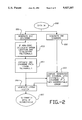
- FIG. 2 is a flow chart illustrating a method according to the present invention.
- FIG. 3 is a diagram of the CRC detection logic utilized in a preferred embodiment of the present invention.
- FIG. 1 is a block diagram of a data storage system implementing the present invention.
- the data storage system includes an optical disk storage media 10 coupled across line 11 to a storage control 12.
- Storage control 12 is coupled across line 13 to data bus 14.
- a memory 15 is coupled to the data bus across line 16.
- ECC syndrome is generated and, if non-zero, supplied across line 20 to logic generating an error polynomial 21. If the ECC syndrome is zero, a control signal indicating the same is supplied on line 20.
- the terms of the error polynomial, or the control signal indicating no errors detected, are supplied across line 23 to CRC detection logic 22, and a CRC syndrome generated by the CRC syndrome generator 19 is supplied across line 24 to the CRC detection logic 22.
- the CRC detection logic 22 generates an estimated CRC syndrome and compares it with the syndrome generated in the CRC generator 19. If the control signal is asserted, indicating no detected errors in the ECC logic, the estimated CRC syndrome is zero.
- the error location and evaluation polynomials are supplied on line 26 to an error vector generator 27.
- the error vector generator 27 is also coupled to receive the uncorrectable error signal on line 25.
- An error vector is then supplied on line 28 to the data bus 14. The error vector can then be utilized in the system to correct the data stored in the memory 15, if no uncorrectable errors were detected.
- FIG. 2 is a flow chart of the method of operation of the system according to the present invention for detecting uncorrectable errors in a sector of data.
- the data is read across the bus (block 200).
- the data on the bus is supplied to ECC syndrome generator and the CRC syndrome generator where the ECC syndrome is generated (block 201) and the CRC syndrome is generated (block 202).
- ECC syndrome is non-zero, then error location and evaluation polynomials are calculated (block 203). From the error evaluation and location polynomials, an estimated CRC syndrome is calculated (block 204). The CRC syndrome generated in block 202 is compared with the CRC syndrome estimated in block 204, and if they are unequal then an uncorrectable error signal is generated (block 205). An error vector is generated in response to the error evaluation and location polynomials and the uncorrectable error signal (block 206). The error vector is then supplied to the system for correction of the data if correctable (block 207).
- Euclid Divide and Polynomial Multiply modules compute the error evaluation and error location polynomials from the generated ECC syndrome polynomial S(x).
- the degree of ⁇ i (x) indicates the expected number of errors in the interleave.
- the next step determines if all errors can be found or an uncorrectable error is present.
- n the degree of ⁇ i (x) then all errors have been found, and the value of the errors is obtained as explained below. If n does not equal the degree of ⁇ i (x) then an uncorrectable error is assumed to be present.
- the estimated CRC syndrome is generated based on terms of the error polynomial e(x).
- the Chien Search implements a searching algorithm for roots of the error polynomial from the highest order to the lowest order with respect to the location of data within the sector. This gives you the lowest order j terms of the error polynomial first and is referred to as a forward Chien Search.
- the CRC syndrome is generated from the high to low orders with respect to the data in the sector. Therefore, all terms of the error polynomial must be generated before calculation of the estimated CRC syndrome may complete.
- the estimated CRC syndrome may be generated as the terms of the error polynomial are generated if a backward Chien Search is utilized.
- each term of the error polynomial as generated is supplied to the CRC detection logic and operated upon.
- the estimated CRC syndrome is supplied. This allows for implementation of the CRC detection logic with less memory, since all terms of the error polynomial need not be stored for generation of the estimated CRC syndrome.
- the estimated CRC syndrome will be available more quickly because less processing is required after receipt of the last term of the error polynomial.
- a forward Chien Search it is preferable to use a forward Chien Search because of convenience of implementation for the variable code lengths possible.
- the length of the interleave must be found by logic before proceeding with the reverse search. This logic for finding the length of the interleave and variable length interleaves complicates implementation of the error detection and correction system.
- a forward Chien Search on the other hand, always begins at the lowest order of the error polynomial.
- a preferred embodiment of the present invention uses a reverse CRC generation polynomial to operate on the error polynomial terms as they proceed from lowest order to highest order.
- n the code length
- s R (x) s 0 x r-1 +s 1 x r-2 + . . . +s r-2 x+s r-1 .
- FIG. 3 illustrates an implementation of the CRC detection block for the reverse CRC syndrome S R (x) according to the preferred embodiment of the present invention.
- the CRC detection logic as shown in FIG. 3 is connected to receive the error polynomial terms as generated across line 23 and the CRC syndrome terms as generated across line 24.
- the CRC syndrome terms on line 24 are supplied first. They are latched in register RI 50 and supplied across line 51 into 2:1 multiplexer 52.
- the control signal LDSEL is asserted to select the signal on line 51 as the output of multiplexer 52 on line 53.
- the term is latched in register RD3 54 in response to the CDRDLAT control signal, and supplied on line 55 through buffer 56 to line 57.
- the first term supplied across line 24 is the high order coefficient S3 of the generated CRC syndrome. This term is supplied through adder 58 into register RS3 59 in response to the RSLAT control signal.
- the second term of the CRC syndrome is supplied through register RD3 54 onto line 57 as a first input to multiplexer 60.
- the LDSEL is signal asserted to select the second term of the CRC syndrome as the output of multiplexer 60 across line 61 to latch RD2 62.
- the latch RD2 62 accepts the second term in response to the CDRDLAT signal, and supplies it on line 63 through buffer 64 to line 65.
- the second term is supplied through adder 66 to latch RS2 67 in response to the RSLAT control signal.
- the third term of the CRC syndrome supplied across line 24 is latched through RD3 and RD2 onto line 65 as an input to 2:1 multiplexer 68.
- the LDSEL signal is asserted to select the third term across line 69 as an input to latch RD1 70.
- the third term is latched in RD1 70 and supplied across line 71 through buffer 72 onto line 73.
- the third term is supplied through adder 74 to latch RS1 75 in response to assertion of the RSLAT signal.
- the fourth term of the CRC syndrome 24 is supplied through RI 50, RD3 54, RD2 62, RD1 70 onto line 73 as an input to 2:1 multiplexer 76.
- the LDSEL signal selects the fourth term as the output of multiplexer 76 on line 77 which is connected to the input of latch RD0 78.
- Latch RD0 stores the fourth term in response to the CDRDLAT signal and supplies it on line 79 through buffer 80 to line 81
- the fourth term is supplied through adder 82 to latch RS0 83 in response to the RSLAT signal. In this manner, the four terms of the CRC syndrome are latched in reverse order in registers RS0 through RS3, to implement a reverse CRC syndrome.
- the error polynomial is supplied through 2:1 multiplexer 84 to line 85, if the CRCDSEL control signal is not asserted.
- the CRCDSEL control signal is asserted to select all zeros through 2:1 multiplexer 84 if the ECC syndrome is zero and no error polynomial is generated.
- registers RD0 through RD3 are reset in response to the RDRST signal.
- the first term of the error polynomial is selected across line 85 through adder 86 and on line 87 as a second input to 2:1 multiplexer 76.
- the LDSEL signal results in selection of the error term through the multiplexer 76 to line 77 and into RD0 78.
- the second term of the error polynomial is supplied across line 85 through adder 86 into RD0 while the first term is supplied on line 81 through adder 88, multiplexer 68, and line 69 into register RD1 70.
- the third term of the error polynomial is selected through adder 86 and multiplexer 76 into RD0 78 while the second term is shifted through adder 88, multiplexer 68 into latch RD1 and the first term is shifted along line 71 through buffer 72, line 73, adder 90, line 91, multiplexer 60, and line 61 into latch RD2 62.
- the fourth term of the error polynomial is shifted into RD0 while the third, second and first terms are shifted through the detection logic as before, with the first term being shifted along line 65 through adder 92, line 93, multiplexer 52, and line 53 into RD3 54.
- RD3 54 The value in RD3 54 is supplied on line 55 through buffer 56 onto line 57 where it is supplied as input to true and complement generator 94.
- True and complement outputs 96 of the signal generated by true and complement generator 94 are supplied as inputs to multipliers 97, 98, 99, and 100, which require the true and complement inputs to perform multiplication.
- Multiplier 97 multiplies the signal on line 96 by ⁇ 77 and supplies its output on line 101 as a second input to adder 86.
- the signal on line 96 is multiplied in multiplier 98 by ⁇ 188 and supplied on line 102 as a second input to adder 88.
- the signal on line 96 is supplied through multiplier 99 where it is multiplied by ⁇ 57 and supplied on line 103 as a second input to adder 90.
- Multiplier 100 multiplies a signal on line 96 by ⁇ 215 and supplies its output on line 104 as a second output to adder 92.
- the terms of the error polynomial are generated, they are successively latched through the CRC detection circuit of FIG. 3 in response to the CDRDLAT signal until all terms have been received.
- the x 4 term of S R (x) can be implemented by shifting four zero terms at the end of the error polynomial into the detection logic of FIG. 3. In an implemented system, the x 4 term is cancelled by shifting four zeros at the end of the data polynomial used into the logic generating CRC syndrome. The effect is the same.
- the RSLAT signal is asserted so that the value in RD0 is summed with the value in RS0 and stored in latch RS0.
- the value in RD1 is summed with the value in RS1 and stored in RS1.
- the value in RD2 is summed with the value in RS2 and latched in RS2.
- the value in RD3 is summed with the value in RS3 and latched into RS3.
- the output of RS0 through RS3 on lines 105 through 108 represent a comparison of the estimated CRC syndrome with the generated CRC syndrome.
- the lines 105 through 108 are connected as inputs to NOR gate 109.
- the output of NOR gate 109 is the uncorrectable error signal on line 25. If any of the signals on line 105 through 108 are non-zero, then the uncorrectable error signal will be asserted active low.
- each interleave value is latched into the registers RS0 through RS3 while being scanned with the result of previous interleaves.
- the uncorrectable error signal is sampled.
- the RSRST signal is asserted to clear the latches RS0 through RS3 in order to initialize the circuit for operation on a following sector.
- this CRC detection logic of FIG. 3 implements the reverse CRC generation polynomial, and calculates an estimated CRC syndrome.
- the estimated CRC syndrome is compared with the CRC syndrome supplied across line 24 and previously stored in the registers RS0 through RS3. Result of the comparison is supplied on line 25 as the uncorrectable error signal.
- the CRC detection logic illustrated in FIG. 3 allows generation of the estimated CRC syndrome in parallel with the generation of the error polynomial.
- the uncorrectable error signal can be generated based on a single read of the sector of data, providing a significant performance advantage over prior art error detection and correction systems based on a first code for detecting and correcting errors and a second code for determining whether uncorrectable errors exist in the sector.
- the representative error detection and correction system for which the present invention is suited is the X3B11 standard for optical storage media on 51/4 inch disks. Such standard is incorporated by reference in the present application as if fully set forth herein.
Abstract
Occurrence of uncorrectable errors in a stored sector of data which includes a data block, an error checking and correcting (ECC) block and an error detecting (CRC) block is detected. ECC logic is connected to a data bus and responsive to the ECC block in the sector, for generating an error polynomial identifying a location and a value for correctable errors in the sector. CRC logic is connected to the data bus and responsive to the CRC block in the sector for generating a syndrome identifying detected errors in the data block. An evaluation logic circuit is included that is coupled to the ECC logic and the CRC logic and responsive to the error polynomial and the syndrome for generating an uncorrectable error signal if the detected errors do not match the correctable errors. The error checking and correcting code is a Reed-Solomon code as in the X3B11 standard. Likewise the CRC code is a Reed-Solomon code as in the X3B11 standard. The evaluation logic implements a reverse CRC generation polynomial having a plurality of terms in the same order as the error polynomial. Detection logic receives the plurality of terms of the error polynomial, generates an estimated CRC syndrome based on the reverse CRC generation polynomial, and generates the uncorrectable error signal if the estimated CRC syndrome is not equal to the generated CRC syndrome.
Description
1. Field of the Invention
The present invention relates to error detection and correction systems employing a first code for detection and correction of errors, and a second code for detecting errors by which the presence of uncorrectable errors is determined.
2. Description of Related Art
A standard encoding specification for 51/4 inch optical storage devices known as X3B11 has been adopted by the data storage systems industry. According to this standard, data is stored in sectors which consist of three or more interleaves of data. A data field error checking and correcting (ECC) code is generated over each interleave and a data field cyclic redundancy code (CRC) is generated over the XOR sum of data bytes across the interleaves, i.e. to the XOR sum of all data bytes with the same displacement from the beginning of each interleave.
The ECC code is utilized to locate and correct correctable errors in each sector. The CRC code is utilized to determine whether errors exist in the sector that may not have been identified and corrected using the ECC code. When such errors are identified, then an uncorrectable sector signal is generated.
Although this X3B11 specification has been implemented for optical disk systems, it is particularly useful for any data storage system characterized by frequent burst errors.
Performance of data storage systems using the ECC/CRC codes for identifying uncorrectable errors is limited by the time required to compare the errors located and corrected by the ECC with those detected by the CRC code. A typical system using the X3B11 standard is required first to read the data of a sector, and then to generate a syndrome based on the ECC code. From the syndrome, error location and error value polynomials are generated and the data is corrected. The corrected data is then read for generation of a CRC syndrome. If the generation of the CRC syndrome based on the corrected data is non-zero, then an uncorrectable error is detected. This algorithm is obviously burdensome in that it requires reading of the entire sector of data twice.
It would be desirable to utilize the two code error checking and correcting systems, such as the X3B11 standard, without requiring two reads of the sector of data involved in the correction, and otherwise improve the performance of error detection and correction systems.
The present invention provides an apparatus for signalling the occurrence of uncorrectable errors in a stored sector of data which includes a data block, an error detecting (CRC) block, and an error checking and correcting (ECC) block. The apparatus includes a data bus which is connected to a storage system for communication of the sector of data. CRC logic is connected to the data bus and responsive to the CRC block in the sector for generating a syndrome identifying detected errors in the data block. ECC logic is connected to the data bus and responsive to the ECC block in the sector, for generating an error polynomial identifying a location and a value for correctable errors in the sector. An evaluation logic circuit is included that is coupled to the ECC logic and the CRC logic and responsive to the error polynomial and the syndrome for generating an uncorrectable error signal if the detected errors do not match the correctable errors.
According to one aspect, the ECC code is a Reed-Solomon code as in the X3B11 standard. Likewise the CRC code is a Reed-Solomon code as in the X3B11 standard. The ECC logic generates the plurality of terms in the error polynomial in an order with respect to the bytes of data in the data block. The CRC syndrome is a second polynomial with a plurality of terms generated in response to a CRC generation polynomial. The evaluation logic implements a reverse CRC generation polynomial. Detection logic receives the plurality of terms of the error polynomial, generates an estimated CRC syndrome based on the reverse CRC generation polynomial, and generates the uncorrectable error signal if the estimated CRC syndrome is not equal to the generated CRC syndrome.
Other aspects and advantages of the present invention can be seen by a study of the figures, detailed description and claims below.
FIG. 1 is a block diagram of a data storage system implementing the present invention.
FIG. 2 is a flow chart illustrating a method according to the present invention.
FIG. 3 is a diagram of the CRC detection logic utilized in a preferred embodiment of the present invention.
The present invention is described with reference to FIGS. 1, 2 and 3.
FIG. 1 is a block diagram of a data storage system implementing the present invention. The data storage system includes an optical disk storage media 10 coupled across line 11 to a storage control 12. Storage control 12 is coupled across line 13 to data bus 14. A memory 15 is coupled to the data bus across line 16. As data is read from the optical disk 10 through storage control 12 into memory 15, the data is written into an ECC syndrome generator 17 and into a CRC syndrome generator 19 across line 18. The ECC syndrome is generated and, if non-zero, supplied across line 20 to logic generating an error polynomial 21. If the ECC syndrome is zero, a control signal indicating the same is supplied on line 20. The terms of the error polynomial, or the control signal indicating no errors detected, are supplied across line 23 to CRC detection logic 22, and a CRC syndrome generated by the CRC syndrome generator 19 is supplied across line 24 to the CRC detection logic 22. As the terms of the error polynomial become available, the CRC detection logic 22 generates an estimated CRC syndrome and compares it with the syndrome generated in the CRC generator 19. If the control signal is asserted, indicating no detected errors in the ECC logic, the estimated CRC syndrome is zero.
If the estimated CRC syndrome and the generated CRC syndrome are equal, then all errors are corrected, otherwise an uncorrectable error signal is generated on line 25 by the CRC detection logic 22.
The error location and evaluation polynomials are supplied on line 26 to an error vector generator 27. The error vector generator 27 is also coupled to receive the uncorrectable error signal on line 25. An error vector is then supplied on line 28 to the data bus 14. The error vector can then be utilized in the system to correct the data stored in the memory 15, if no uncorrectable errors were detected.
FIG. 2 is a flow chart of the method of operation of the system according to the present invention for detecting uncorrectable errors in a sector of data.
First, the data is read across the bus (block 200). The data on the bus is supplied to ECC syndrome generator and the CRC syndrome generator where the ECC syndrome is generated (block 201) and the CRC syndrome is generated (block 202).
If the ECC syndrome is non-zero, then error location and evaluation polynomials are calculated (block 203). From the error evaluation and location polynomials, an estimated CRC syndrome is calculated (block 204). The CRC syndrome generated in block 202 is compared with the CRC syndrome estimated in block 204, and if they are unequal then an uncorrectable error signal is generated (block 205). An error vector is generated in response to the error evaluation and location polynomials and the uncorrectable error signal (block 206). The error vector is then supplied to the system for correction of the data if correctable (block 207).
Euclid Divide and Polynomial Multiply modules compute the error evaluation and error location polynomials from the generated ECC syndrome polynomial S(x).
______________________________________
Euclid Divide    Polynomial Multiply
______________________________________
0.               Initial Value of Λ Polynomial
                 Λ.sub.0 (x) = 1,Λ.sub.-1 (x) = 0
 ##STR1##        Λ.sub.1 (x) = q.sub.1 (x)*Λ.sub.0 (x) +
                 Λ.sub.-1 (x)
 ##STR2##        Λ.sub.2 (x) = q.sub.2 (x)*Λ.sub.1 (x) +
                 Λ.sub.0 (x)
  .              .
  .              .
  .              .
 ##STR3##        Λ.sub.i (x) = q.sub.i (x)*Λ.sub.i-1 (x) +
                 Λ.sub.i-2 (x)
______________________________________
Repeat until the degree of ri (x) is less than 8.
ri (x)=Ω(x)=Error Evaluation polynomial
Λi (x)=Error Location polynomial
The degree of Λi (x) indicates the expected number of errors in the interleave. The next step determines if all errors can be found or an uncorrectable error is present.
The Chien Search logic evaluates the Error Location Polynomial Λi (x) at α255, . . . , α255-k, where k is the code length of the interleave. An error is assumed present at offset j if Λi (α255-j)=0. Logic counts the number of roots (zeroes) of Λi (x) that are found (say n).
If n equals the degree of Λi (x) then all errors have been found, and the value of the errors is obtained as explained below. If n does not equal the degree of Λi (x) then an uncorrectable error is assumed to be present.
For each iteration of the Chien Search logic, Error Evaluator/Polynomial Derivative logic computes an error value: ##EQU1## where Λ'i (α255-j) is the derivative of the Error Location Polynomial. Ej is the error value for the byte at offset j when Λi (α255-j)=0. Terms j of the error polynomial are then defined as e(x)=Ej xj. Each term Ej can be combined with data location xj to correct detected errors.
The estimated CRC syndrome is generated based on terms of the error polynomial e(x).
The Chien Search implements a searching algorithm for roots of the error polynomial from the highest order to the lowest order with respect to the location of data within the sector. This gives you the lowest order j terms of the error polynomial first and is referred to as a forward Chien Search.
The CRC syndrome is generated from the high to low orders with respect to the data in the sector. Therefore, all terms of the error polynomial must be generated before calculation of the estimated CRC syndrome may complete.
The estimated CRC syndrome may be generated as the terms of the error polynomial are generated if a backward Chien Search is utilized. In this embodiment, each term of the error polynomial as generated is supplied to the CRC detection logic and operated upon. When the last term of the error polynomial is supplied to the CRC detection logic, the estimated CRC syndrome is supplied. This allows for implementation of the CRC detection logic with less memory, since all terms of the error polynomial need not be stored for generation of the estimated CRC syndrome. In addition, the estimated CRC syndrome will be available more quickly because less processing is required after receipt of the last term of the error polynomial.
It is preferable to use a forward Chien Search because of convenience of implementation for the variable code lengths possible. Using a backward Chien Search, the length of the interleave must be found by logic before proceeding with the reverse search. This logic for finding the length of the interleave and variable length interleaves complicates implementation of the error detection and correction system. A forward Chien Search, on the other hand, always begins at the lowest order of the error polynomial.
However, since the order of the error locations coming out of a forward Chien Search block is reversed, a preferred embodiment of the present invention uses a reverse CRC generation polynomial to operate on the error polynomial terms as they proceed from lowest order to highest order.
If e(x) is an error polynomial,
e(x)=e.sub.0 +e.sub.1 x+e.sub.2 x.sup.2 + . . . +e.sub.n-2 x.sup.n-2 +e.sub.n-1 x.sup.n-1
where ei can be 0 for i=0, 1, . . . , n-1.
Then with a forward Chien Search, the order of the coefficients generated goes from e0 to en-1. And with a backward Chien Search en-1 comes first and e0 comes last.
The following proof demonstrates that the CRC syndrome polynomial s(x) can be calculated from the error value polynomial and the CRC generation polynomial.
______________________________________
Let       i(x)   = information polynomial,
          g(x)   = CRC generation polynomial,
          c(x)   = codeword polynomial,
          e(x)   = error polynomial,
          r(x)   = received codeword polynomial,
and       s(x)   = CRC syndrome polynomial
          with   deg [g(x)] = r.
Then      c(x)   = i(x) · x.sup.r + [i(x) · x.sup.r ]
                 mod g(x),
          r(x)   = c(x) + e(x),
and       s(x)   = r(x) mod g(x).
Then      s(x)   = r(x) mod g(x)
                 = [c(x) + e(x)] mod g(x)
                 = c(X) mod g(x) + e(x) mod g(x).
                 = e(x) mod g(x)
______________________________________
So if error estimation is correct, then s(x)=r(x) mod g(x) from CRC syndrome generation block should be the same as e(x) mod g(x) using estimated errors from error value and location generation unit.
If not, uncorrectable errors occurred.
The following proof demonstrates that the reciprocal of the CRC syndrome can be generated from the results of a forward Chien Search and a reverse CRC generation polynomial.
______________________________________
Forward Chien Search:
                   e.sub.0, e.sub.1, e.sub.2, . . ., e.sub.n-2,
                   e.sub.n-1
                   in availability order
Backward Chien Search:
                   e.sub.n-1, e.sub.n-2, . . ., e.sub.2, e.sub.1,
                   e.sub.0
                   in order of availability
______________________________________
Let n be the code length.
With e(x)=en-1 xn-1 +en-2 xn-2 + . . . +e1 x+e0
where e1 can be 0, i=0, 1, ..., n-1,
Let eR (x)=e0 xn-1 e1 xn-2 + . . . +en-2 x+en-1.
With g(x)=xr +gr-1 xr-1 + . . . +g1 x+g0,
gR (x)=g0 xr +g1 xr-1 + . . . +gr-1 x+1=g0 gRN (x).
With s(x)=sr-1 xr-1 +sr-2 xr-2 + . . . +s1 x+s0,
sR (x)=s0 xr-1 +s1 xr-2 + . . . +sr-2 x+sr-1.
Then from s(x)=e(x) mod g(x) ##EQU2##
For a standard X3B11 implementation, the reverse CRC generation polynomial is calculated as follows. ##EQU3##
FIG. 3 illustrates an implementation of the CRC detection block for the reverse CRC syndrome SR (x) according to the preferred embodiment of the present invention.
The CRC detection logic as shown in FIG. 3 is connected to receive the error polynomial terms as generated across line 23 and the CRC syndrome terms as generated across line 24. The CRC syndrome terms on line 24 are supplied first. They are latched in register RI 50 and supplied across line 51 into 2:1 multiplexer 52. During loading of the CRC syndrome terms, the control signal LDSEL is asserted to select the signal on line 51 as the output of multiplexer 52 on line 53. The term is latched in register RD3 54 in response to the CDRDLAT control signal, and supplied on line 55 through buffer 56 to line 57.
The first term supplied across line 24 is the high order coefficient S3 of the generated CRC syndrome. This term is supplied through adder 58 into register RS3 59 in response to the RSLAT control signal.
The second term of the CRC syndrome is supplied through register RD3 54 onto line 57 as a first input to multiplexer 60. The LDSEL is signal asserted to select the second term of the CRC syndrome as the output of multiplexer 60 across line 61 to latch RD2 62. The latch RD2 62 accepts the second term in response to the CDRDLAT signal, and supplies it on line 63 through buffer 64 to line 65. The second term is supplied through adder 66 to latch RS2 67 in response to the RSLAT control signal.
The third term of the CRC syndrome supplied across line 24 is latched through RD3 and RD2 onto line 65 as an input to 2:1 multiplexer 68. The LDSEL signal is asserted to select the third term across line 69 as an input to latch RD1 70. In response to a third assertion of CDRDLAT, the third term is latched in RD1 70 and supplied across line 71 through buffer 72 onto line 73. The third term is supplied through adder 74 to latch RS1 75 in response to assertion of the RSLAT signal. The fourth term of the CRC syndrome 24 is supplied through RI 50, RD3 54, RD2 62, RD1 70 onto line 73 as an input to 2:1 multiplexer 76. The LDSEL signal selects the fourth term as the output of multiplexer 76 on line 77 which is connected to the input of latch RD0 78. Latch RD0 stores the fourth term in response to the CDRDLAT signal and supplies it on line 79 through buffer 80 to line 81 The fourth term is supplied through adder 82 to latch RS0 83 in response to the RSLAT signal. In this manner, the four terms of the CRC syndrome are latched in reverse order in registers RS0 through RS3, to implement a reverse CRC syndrome.
After loading of the CRC syndrome, the error polynomial is supplied through 2:1 multiplexer 84 to line 85, if the CRCDSEL control signal is not asserted. The CRCDSEL control signal is asserted to select all zeros through 2:1 multiplexer 84 if the ECC syndrome is zero and no error polynomial is generated.
First, registers RD0 through RD3 are reset in response to the RDRST signal. The first term of the error polynomial is selected across line 85 through adder 86 and on line 87 as a second input to 2:1 multiplexer 76. The LDSEL signal results in selection of the error term through the multiplexer 76 to line 77 and into RD0 78. The second term of the error polynomial is supplied across line 85 through adder 86 into RD0 while the first term is supplied on line 81 through adder 88, multiplexer 68, and line 69 into register RD1 70. The third term of the error polynomial is selected through adder 86 and multiplexer 76 into RD0 78 while the second term is shifted through adder 88, multiplexer 68 into latch RD1 and the first term is shifted along line 71 through buffer 72, line 73, adder 90, line 91, multiplexer 60, and line 61 into latch RD2 62. Finally, the fourth term of the error polynomial is shifted into RD0 while the third, second and first terms are shifted through the detection logic as before, with the first term being shifted along line 65 through adder 92, line 93, multiplexer 52, and line 53 into RD3 54. The value in RD3 54 is supplied on line 55 through buffer 56 onto line 57 where it is supplied as input to true and complement generator 94. True and complement outputs 96 of the signal generated by true and complement generator 94 are supplied as inputs to multipliers 97, 98, 99, and 100, which require the true and complement inputs to perform multiplication.
As the terms of the error polynomial are generated, they are successively latched through the CRC detection circuit of FIG. 3 in response to the CDRDLAT signal until all terms have been received. The x4 term of SR (x) can be implemented by shifting four zero terms at the end of the error polynomial into the detection logic of FIG. 3. In an implemented system, the x4 term is cancelled by shifting four zeros at the end of the data polynomial used into the logic generating CRC syndrome. The effect is the same.
When all terms have been received, the RSLAT signal is asserted so that the value in RD0 is summed with the value in RS0 and stored in latch RS0. The value in RD1 is summed with the value in RS1 and stored in RS1. The value in RD2 is summed with the value in RS2 and latched in RS2. Finally, the value in RD3 is summed with the value in RS3 and latched into RS3.
For a single interleave sector, the output of RS0 through RS3 on lines 105 through 108 represent a comparison of the estimated CRC syndrome with the generated CRC syndrome.
The lines 105 through 108 are connected as inputs to NOR gate 109. The output of NOR gate 109 is the uncorrectable error signal on line 25. If any of the signals on line 105 through 108 are non-zero, then the uncorrectable error signal will be asserted active low.
For a sector involving a plurality of interleaves, each interleave value is latched into the registers RS0 through RS3 while being scanned with the result of previous interleaves. On receipt of the final term of the final interleave, the uncorrectable error signal is sampled.
After performance of the CRC detection using the circuit of FIG. 3, the RSRST signal is asserted to clear the latches RS0 through RS3 in order to initialize the circuit for operation on a following sector.
As can be seen, this CRC detection logic of FIG. 3 implements the reverse CRC generation polynomial, and calculates an estimated CRC syndrome. The estimated CRC syndrome is compared with the CRC syndrome supplied across line 24 and previously stored in the registers RS0 through RS3. Result of the comparison is supplied on line 25 as the uncorrectable error signal.
Equivalent circuits could be implemented in which the CRC syndrome on line 24 is stored in latches separate from RS0 through RS3. The outputs of such latches could be compared using XOR gates or other comparators as known in the art without requiring loading of the RS0 through RS3 latches with the generated CRC syndrome from line 24.
The CRC detection logic illustrated in FIG. 3 allows generation of the estimated CRC syndrome in parallel with the generation of the error polynomial. In addition, the uncorrectable error signal can be generated based on a single read of the sector of data, providing a significant performance advantage over prior art error detection and correction systems based on a first code for detecting and correcting errors and a second code for determining whether uncorrectable errors exist in the sector.
The representative error detection and correction system for which the present invention is suited is the X3B11 standard for optical storage media on 51/4 inch disks. Such standard is incorporated by reference in the present application as if fully set forth herein.
The foregoing description of preferred embodiments of the present invention has been provided for the purposes of illustration and description. It is not intended to be exhaustive or to limit the invention to the precise forms disclosed. Obviously, many modifications and variations will be apparent to practitioners skilled in this art. The embodiments were chosen and described in order to best explain the principles of the invention and its practical application, thereby enabling others skilled in the art to understand the invention for various embodiments and with various modifications as are suited to the particular use contemplated. It is intended that the scope of the invention be defined by the following claims and their equivalents.
Claims (25)
1. In a data storage system storing sectors of data in a store, each sector including a data block, an error checking and correcting (ECC) block, and an error detecting (ED) block, an apparatus for signalling the occurrence of uncorrectable errors in a sector, the apparatus comprising:
a data bus, connected to the store, for communication of the sector;
first means, connected to the data bus and responsive to the ECC block in the sector, for generating an error polynomial identifying location and value for correctable errors in the sector;
second means, connected to the data bus and responsive to the ED block in the sector, for generating a syndrome identifying detected errors in the data block; and
evaluation means, coupled to the first means and the second means and responsive to the error polynomial and the syndrome, for generating an uncorrectable error signal if the detected errors do not match the correctable errors;
wherein the first means includes means for performing a forward Chien Search over the sector so that the error polynomial has an order with respect to bytes of data within the data block, and wherein the syndrome is generated in a reverse order with respect to the order.
2. In a data storage system storing sectors of data in a store, each sector including a data block, an error checking and correcting (ECC) block, and an error detecting (ED) block, an apparatus for signalling the occurrence of uncorrectable errors in a sector, the apparatus comprising:
a data bus, connected to the store, for communication of the sector;
first means, connected to the data bus and responsive to the ECC block in the sector, for generating an error polynomial identifying location and value for correctable errors in the sector, wherein the error polynomial has a plurality of terms, and the first means generates the plurality of terms of the error polynomial from low order to high order with respect to bytes of data in the data block;
second means, connected to the data bus and responsive to the ED block in the sector, for generating a syndrome identifying detected errors in the data block, wherein the syndrome is a second polynomial with a plurality of terms, and the second means generates the plurality of terms in the second polynomial from high order to low order based on a CRC generation polynomial with a plurality of terms; and
evaluation means, coupled to the first means and the second means and responsive to the error polynomial and the syndrome, for generating an uncorrectable error signal if the detected errors do not match the correctable errors.
3. The apparatus of claim 2, wherein:
the first means includes means for performing a backward Chien Search over the sector.
4. The apparatus of claim 2, wherein:
the ECC block is a first Reed-Solomon polynomial; and
the ED block is a second Reed-Solomon polynomial.
5. The apparatus of claim 4, wherein:
the first Reed-Solomon polynomial and the second Reed-Solomon polynomial are specified by international standard X3B11 for 51/4 inch optical storage media.
6. The apparatus of claim 2, wherein the evaluation means includes:
means for reversing the second polynomial to generate a reverse second polynomial having a plurality of terms from low order to high order; and
detection means, coupled with the means for reversing and receiving the plurality of terms of the error polynomial as generated and responsive to the reverse second polynomial, for generating the uncorrectable error signal.
7. The apparatus of claim 6, wherein:
the plurality of terms of the error polynomial includes a final term that is received last by the detection means; and
the detection means generates the uncorrectable error signal in response to receiving the final term.
8. The apparatus of claim 6, wherein the detection means includes:
means for combining the error polynomial with a reverse CRC generation polynomial to generate an estimated reverse second polynomial; and
means, connected to the means for combining and the means for reversing, for comparing the reverse second polynomial with the estimated reverse second polynomial to indicate the occurrence of uncorrectable errors.
9. The apparatus of claim 8, wherein:
the plurality of terms of the error polynomial includes a final term that is received last by the detection means; and
the detection means generates the uncorrectable error signal in response to receiving the final term.
10. In a data storage system storing sectors of data in a store, each sector including a data block, an error checking and correcting (ECC) block, and an error detecting (ED) block, a method for signalling the occurrence of uncorrectable errors in a sector, the method comprising the steps of:
communicating the sector across a data bus;
generating, in error detecting and correcting logic in response to the sector on the data bus, an error polynomial including a plurality of terms, the error polynomial identifying location and value for correctable errors in the sector;
generating, in error detecting logic in response to the sector on the data bus, a syndrome identifying detected errors in the data block, and storing the syndrome; and
generating, in combining logic in response to the error polynomial and the syndrome, an uncorrectable error signal if the detected errors do not match the correctable errors;
wherein the step of generating an error polynomial includes performing a forward Chien Search over the sector so that the error vector has an order with respect to bytes of data within the data block, and wherein the syndrome is generated in a reverse order with respect to the order.
11. In a data storage system storing sectors of data in a store, each sector including a data block, an error checking and correcting (ECC) block, and an error detecting (ED) block, a method for signalling the occurrence of uncorrectable errors in a sector, the method comprising the steps of:
communicating the sector across a data bus;
generating, in error detecting and correcting logic in response to the sector on the data bus, an error polynomial including a plurality of terms, the error polynomial identifying location and value for correctable errors in the sector, the plurality of terms of the error polynomial being generated from low order to high order with respect to bytes of data in the data block;
generating, in error detecting logic in response to the sector on the data bus, a syndrome identifying detected errors in the data block, and storing the syndrome, the syndrome being a second polynomial with a plurality of terms, the plurality of terms in the second polynomial being generated from high order to low order based on a CRC generation polynomial with a plurality of terms; and
generating, in combining logic in response to the error polynomial and the syndrome, an uncorrectable error signal if the detected errors do not match the correctable errors.
12. The method of claim 11, wherein:
the step of generating an error polynomial includes performing a backward Chien Search over the sector.
13. The method of claim 11, wherein: the ECC block is a first Reed-Solomon polynomial and the ED block is a second Reed-Solomon polynomial.
14. The method of claim 13, wherein:
the first Reed-Solomon polynomial and the second Reed-Solomon polynomial are specified by international standard X3B11 for 51/4 inch optical storage media.
15. The method of claim 11, wherein the step of generating an uncorrectable error signal includes:
reversing the second polynomial to implement a reverse second polynomial having a plurality of terms from low order to high order; and
generating the uncorrectable error signal in response to the plurality of terms of the error polynomial and to the reverse second polynomial.
16. The method of claim 15, wherein:
the plurality of terms of the error polynomial includes a final term; and
the step of generating the uncorrectable error signal generates the uncorrectable error signal upon receipt of the final term.
17. The method of claim 15, wherein the step of generating the uncorrectable error signal includes:
combining the error polynomial with a reverse CRC generation polynomial to generate an estimated reverse second polynomial; and
comparing the reverse second polynomial with the estimated reverse second polynomial to indicate the occurrence of uncorrectable errors.
18. The method of claim 17, wherein:
the plurality of terms of the error polynomial includes a final term that is received last; and
the uncorrectable error signal is generated upon receipt of the final term.
19. In a data storage system storing sectors of data in a store, each sector including a data block, an error checking and correcting (ECC) block, and an error detecting (ED) block, an apparatus for signalling the occurrence of uncorrectable errors in a sector, the apparatus comprising:
a data bus, connected to the store, for communication of the sector;
first means, connected to the data bus and responsive to the ECC block in the sector, for generating an error polynomial identifying location and value for correctable errors in the sector, wherein the error polynomial has a plurality of terms generated from low order to high order with respect to bytes of data in the data block;
second means, connected to the data bus and responsive to the ED block in the sector, for generating a syndrome identifying detected errors in the data block, wherein the syndrome is a second polynomial with a plurality of terms generated from high order to low order based on a CRC generation polynomial with a plurality of terms;
means for reversing the second polynomial to implement a reverse second polynomial having a plurality of terms from low order to high order; and
detection means, coupled with the means for reversing, and receiving the plurality of terms of the error polynomial as generated and responsive to the reverse second polynomial, for generating an uncorrectable error signal if the detected errors do not match the correctable errors.
20. The apparatus of claim 19, wherein:
the plurality of terms of the error polynomial includes a final term that is received last by the detection means; and
the detection means generates the uncorrectable error signal in response to receiving the final term.
21. The apparatus of claim 19, wherein the detection means includes:
means for combining the error polynomial with a reverse CRC generation polynomial to generate an estimated reverse second polynomial; and
means, connected to the means for combining and the means for reversing, for comparing the reverse second polynomial with the estimated reverse second polynomial to indicate the occurrence of uncorrectable errors.
22. The apparatus of claim 19, wherein:
the first means includes means for performing a forward Chien Search over the sector.
23. The apparatus of claim 19, wherein:
the first means includes means for performing a backward Chien Search over the sector.
24. The apparatus of claim 19, wherein: the ECC block is a first Reed-Solomon polynomial; and the ED block is a second Reed-Solomon polynomial.
25. The apparatus of claim 24, wherein:
the first Reed-Solomon polynomial and the second Reed-Solomon polynomial are specified by international standard X3B11 for 51/4 inch optical storage media.
Priority Applications (4)
| Application Number | Priority Date | Filing Date | Title |
|---|---|---|---|
| US07/258,240 US5027357A (en) | 1988-10-14 | 1988-10-14 | ECC/CRC error detection and correction system |
| EP19890310257 EP0364172A3 (en) | 1988-10-14 | 1989-10-06 | Error detection and correction for a data storage system |
| JP1267968A JPH02211723A (en) | 1988-10-14 | 1989-10-14 | Device and method for sending signal of unconnectable error geberation in sector |
| US07/690,114 US5157669A (en) | 1988-10-14 | 1991-04-23 | Comparison of an estimated CRC syndrome to a generated CRC syndrome in an ECC/CRC system to detect uncorrectable errors |
Applications Claiming Priority (1)
| Application Number | Priority Date | Filing Date | Title |
|---|---|---|---|
| US07/258,240 US5027357A (en) | 1988-10-14 | 1988-10-14 | ECC/CRC error detection and correction system |
Related Child Applications (1)
| Application Number | Title | Priority Date | Filing Date |
|---|---|---|---|
| US07/690,114 Continuation US5157669A (en) | 1988-10-14 | 1991-04-23 | Comparison of an estimated CRC syndrome to a generated CRC syndrome in an ECC/CRC system to detect uncorrectable errors |
Publications (1)
| Publication Number | Publication Date |
|---|---|
| US5027357A true US5027357A (en) | 1991-06-25 |
Family
ID=22979693
Family Applications (1)
| Application Number | Title | Priority Date | Filing Date |
|---|---|---|---|
| US07/258,240 Expired - Lifetime US5027357A (en) | 1988-10-14 | 1988-10-14 | ECC/CRC error detection and correction system |
Country Status (3)
| Country | Link |
|---|---|
| US (1) | US5027357A (en) |
| EP (1) | EP0364172A3 (en) |
| JP (1) | JPH02211723A (en) |
Cited By (51)
| Publication number | Priority date | Publication date | Assignee | Title |
|---|---|---|---|---|
| US5157669A (en) * | 1988-10-14 | 1992-10-20 | Advanced Micro Devices, Inc. | Comparison of an estimated CRC syndrome to a generated CRC syndrome in an ECC/CRC system to detect uncorrectable errors |
| US5325372A (en) * | 1990-08-07 | 1994-06-28 | National Semiconductor Corporation | Implementation of the HDLC CRC calculation |
| US5361266A (en) * | 1992-11-04 | 1994-11-01 | Mitsubishi Denki Kabushiki Kaisha | Error correction circuit |
| US5379415A (en) * | 1992-09-29 | 1995-01-03 | Zitel Corporation | Fault tolerant memory system |
| US5384788A (en) * | 1992-10-26 | 1995-01-24 | Dell Usa, L.P. | Apparatus and method for optimal error correcting code to parity conversion |
| US5432801A (en) * | 1993-07-23 | 1995-07-11 | Commodore Electronics Limited | Method and apparatus for performing multiple simultaneous error detection on data having unknown format |
| US5631915A (en) * | 1995-03-31 | 1997-05-20 | International Business Machines Corporation | Method of correcting single errors |
| US5719885A (en) * | 1995-12-28 | 1998-02-17 | Emc Corporation | Storage reliability method and apparatus |
| US5734663A (en) * | 1991-12-18 | 1998-03-31 | International Business Machines Corporation | Abbreviated trial-and-error technique for correcting long bursts of consecutive errors using CRC bytes |
| US5774647A (en) * | 1996-05-15 | 1998-06-30 | Hewlett-Packard Company | Management of memory modules |
| US5822339A (en) * | 1996-05-30 | 1998-10-13 | Rockwell International | Data decoder and method to correct inversions or phase ambiguity for M-ary transmitted data |
| US5991911A (en) * | 1997-11-14 | 1999-11-23 | Cirrus Logic, Inc. | Concurrent generation of ECC error syndromes and CRC validation syndromes in a DVD storage device |
| US5996105A (en) * | 1997-11-14 | 1999-11-30 | Cirrus Logic, Inc. | ECC system employing a data buffer for storing codeword data and a syndrome buffer for storing error syndromes |
| US6052815A (en) * | 1997-11-14 | 2000-04-18 | Cirrus Logic, Inc. | ECC system for generating a CRC syndrome over randomized data in a computer storage device |
| US6092231A (en) * | 1998-06-12 | 2000-07-18 | Qlogic Corporation | Circuit and method for rapid checking of error correction codes using cyclic redundancy check |
| US6115837A (en) * | 1998-07-29 | 2000-09-05 | Neomagic Corp. | Dual-column syndrome generation for DVD error correction using an embedded DRAM |
| US6158040A (en) * | 1998-07-29 | 2000-12-05 | Neomagic Corp. | Rotated data-aligmnent in wade embedded DRAM for page-mode column ECC in a DVD controller |
| US6438724B1 (en) | 1999-03-16 | 2002-08-20 | International Business Machines Corporation | Method and apparatus for deterministically altering cyclic redundancy check information for data storage |
| US6446234B1 (en) | 1999-03-16 | 2002-09-03 | International Business Machines Corporation | Method and apparatus for updating cyclic redundancy check information for data storage |
| US20030140302A1 (en) * | 2002-01-23 | 2003-07-24 | Litwin, Louis Robert | Chien search cell for an error-correcting decoder |
| US20040088497A1 (en) * | 2002-11-06 | 2004-05-06 | Deans Russell C. | Methods and apparatus for exchanging data using cyclic redundancy check codes |
| US6751771B2 (en) | 2000-02-11 | 2004-06-15 | Mediatek, Inc. | Method and apparatus for error processing in optical disk memories |
| US20040193743A1 (en) * | 2003-03-10 | 2004-09-30 | Byers Larry L. | Servo controller interface module for embedded disk controllers |
| US20040199711A1 (en) * | 2003-03-10 | 2004-10-07 | Byers Larry L. | Method and system for using an external bus controller in embedded disk controllers |
| US20040205442A1 (en) * | 2001-02-07 | 2004-10-14 | Mediatek, Inc. | Method and apparatus for error processing in optical disk memories |
| US20050174680A1 (en) * | 2004-02-10 | 2005-08-11 | Spaur Michael R. | Method and system for head position control in embedded disk drive controllers |
| US20050276151A1 (en) * | 2004-06-14 | 2005-12-15 | White Theodore C | Integrated memory controller |
| US20050289261A1 (en) * | 2004-06-28 | 2005-12-29 | White Theodore C | System and method for reading and writing data using storage controllers |
| US20060015774A1 (en) * | 2004-07-19 | 2006-01-19 | Nguyen Huy T | System and method for transmitting data in storage controllers |
| US20060015654A1 (en) * | 2004-07-19 | 2006-01-19 | Krantz Leon A | Dynamic WWN module for storage controllers |
| US20060015660A1 (en) * | 2004-07-19 | 2006-01-19 | Kha Nguyen | System and method for controlling buffer memory overflow and underflow conditions in storage controllers |
| US20060020871A1 (en) * | 2004-07-21 | 2006-01-26 | Fujitsu Limited | Communications device and wireless communications system |
| US7007114B1 (en) | 2003-01-31 | 2006-02-28 | Qlogic Corporation | System and method for padding data blocks and/or removing padding from data blocks in storage controllers |
| US7039771B1 (en) | 2003-03-10 | 2006-05-02 | Marvell International Ltd. | Method and system for supporting multiple external serial port devices using a serial port controller in embedded disk controllers |
| US20060104269A1 (en) * | 2004-11-15 | 2006-05-18 | Perozo Angel G | Method and system for processing frames in storage controllers |
| US20060117235A1 (en) * | 2004-11-08 | 2006-06-01 | Dinesh Jayabharathi | System and method for conducting BIST operations |
| US7064915B1 (en) | 2003-03-10 | 2006-06-20 | Marvell International Ltd. | Method and system for collecting servo field data from programmable devices in embedded disk controllers |
| US7111228B1 (en) | 2002-05-07 | 2006-09-19 | Marvell International Ltd. | System and method for performing parity checks in disk storage system |
| US20060227447A1 (en) * | 2005-04-06 | 2006-10-12 | Pinvidic Daniel R | Method and system for read gate timing control for storage controllers |
| US7228485B1 (en) | 2003-04-03 | 2007-06-05 | Marvell International Ltd. | Error correction using error detection codes |
| US7287102B1 (en) | 2003-01-31 | 2007-10-23 | Marvell International Ltd. | System and method for concatenating data |
| US7386661B2 (en) | 2004-10-13 | 2008-06-10 | Marvell International Ltd. | Power save module for storage controllers |
| US20080141099A1 (en) * | 2002-05-22 | 2008-06-12 | International Business Machines Corporation | Data Storage Device And Data Processing Method |
| US7492545B1 (en) | 2003-03-10 | 2009-02-17 | Marvell International Ltd. | Method and system for automatic time base adjustment for disk drive servo controllers |
| US7526691B1 (en) | 2003-10-15 | 2009-04-28 | Marvell International Ltd. | System and method for using TAP controllers |
| US20100313102A1 (en) * | 2009-06-04 | 2010-12-09 | A-Data Technology (Suzhou) Co., Ltd. | Electronic storage device and control method thereof |
| US20110047441A1 (en) * | 2008-03-01 | 2011-02-24 | Kabushiki Kaisha Toshiba | Chien search device and chien search method |
| US7937643B1 (en) | 2006-09-18 | 2011-05-03 | Mediatek Inc. | Mobile communication device and data reception method |
| US8578240B1 (en) * | 2011-01-21 | 2013-11-05 | Juniper Networks, Inc. | CRC computation for packet length not multiple of data path width |
| US8762818B1 (en) * | 2009-03-05 | 2014-06-24 | Marvell International Ltd. | System and methods for performing decoding error detection in a storage device |
| US9298529B2 (en) | 2014-05-29 | 2016-03-29 | Freescale Semiconductor, Inc. | Indicating internal transmitter errors in a controller area network (CAN) |
Families Citing this family (6)
| Publication number | Priority date | Publication date | Assignee | Title |
|---|---|---|---|---|
| US5140596A (en) * | 1990-02-20 | 1992-08-18 | Eastman Kodak Company | High speed encoder for non-systematic codes |
| JP2591242B2 (en) * | 1990-04-02 | 1997-03-19 | 松下電器産業株式会社 | Error detection method |
| ES2066723B1 (en) * | 1993-05-25 | 1995-11-01 | Contadores De Agua De Zaragoza | IMPROVEMENTS FOR FLUID METERS. |
| US5465260A (en) * | 1993-11-04 | 1995-11-07 | Cirrus Logic, Inc. | Dual purpose cyclic redundancy check |
| US5592404A (en) * | 1993-11-04 | 1997-01-07 | Cirrus Logic, Inc. | Versatile error correction system |
| KR100594241B1 (en) * | 2004-01-29 | 2006-06-30 | 삼성전자주식회사 | RS decoder circuit having forward Chien search type |
Citations (1)
| Publication number | Priority date | Publication date | Assignee | Title |
|---|---|---|---|---|
| US4750178A (en) * | 1985-04-13 | 1988-06-07 | Sony Corporation | Error correction method |
Family Cites Families (3)
| Publication number | Priority date | Publication date | Assignee | Title |
|---|---|---|---|---|
| EP0156440B1 (en) * | 1984-03-24 | 1990-01-24 | Koninklijke Philips Electronics N.V. | An information transmission method with error correction for user words, an error correcting decoding method for such user words, an apparatus for information transmission for use with the method, a device for information decoding for use with the method and an apparatus for use with such device |
| JPH07101544B2 (en) * | 1985-05-13 | 1995-11-01 | 松下電器産業株式会社 | Error detector |
| JP2605271B2 (en) * | 1987-02-10 | 1997-04-30 | ソニー株式会社 | Error correction and checking device |
-
1988
- 1988-10-14 US US07/258,240 patent/US5027357A/en not_active Expired - Lifetime
-
1989
- 1989-10-06 EP EP19890310257 patent/EP0364172A3/en not_active Withdrawn
- 1989-10-14 JP JP1267968A patent/JPH02211723A/en active Pending
Patent Citations (1)
| Publication number | Priority date | Publication date | Assignee | Title |
|---|---|---|---|---|
| US4750178A (en) * | 1985-04-13 | 1988-06-07 | Sony Corporation | Error correction method |
Non-Patent Citations (6)
| Title |
|---|
| Adaptec Programmable Storage Controller AIC 010F 10 . . . , preliminary data sheets, Aug. 1986, pp. 1 13, 16 32. * |
| Adaptec Programmable Storage Controller AIC-010F-10 . . . , preliminary data sheets, Aug. 1986, pp. 1-13, 16-32. |
| Chien, R., "Cyclic Decoding Procedures for Bose-Chaudhuri-Hocquenghem Codes", IEEE Trans. on Information Theory, Oct. 1964, pp. 357-363. |
| Chien, R., Cyclic Decoding Procedures for Bose Chaudhuri Hocquenghem Codes , IEEE Trans. on Information Theory, Oct. 1964, pp. 357 363. * |
| Shao, H. et al., "A VLSI Design of a Pipeline Reed-Solomon Decoder", IEEE Trans. on Computers, May 1985, pp. 393-403. |
| Shao, H. et al., A VLSI Design of a Pipeline Reed Solomon Decoder , IEEE Trans. on Computers, May 1985, pp. 393 403. * |
Cited By (100)
| Publication number | Priority date | Publication date | Assignee | Title |
|---|---|---|---|---|
| US5157669A (en) * | 1988-10-14 | 1992-10-20 | Advanced Micro Devices, Inc. | Comparison of an estimated CRC syndrome to a generated CRC syndrome in an ECC/CRC system to detect uncorrectable errors |
| US5325372A (en) * | 1990-08-07 | 1994-06-28 | National Semiconductor Corporation | Implementation of the HDLC CRC calculation |
| US5734663A (en) * | 1991-12-18 | 1998-03-31 | International Business Machines Corporation | Abbreviated trial-and-error technique for correcting long bursts of consecutive errors using CRC bytes |
| US5379415A (en) * | 1992-09-29 | 1995-01-03 | Zitel Corporation | Fault tolerant memory system |
| US5553231A (en) * | 1992-09-29 | 1996-09-03 | Zitel Corporation | Fault tolerant memory system |
| US5384788A (en) * | 1992-10-26 | 1995-01-24 | Dell Usa, L.P. | Apparatus and method for optimal error correcting code to parity conversion |
| US5361266A (en) * | 1992-11-04 | 1994-11-01 | Mitsubishi Denki Kabushiki Kaisha | Error correction circuit |
| US5432801A (en) * | 1993-07-23 | 1995-07-11 | Commodore Electronics Limited | Method and apparatus for performing multiple simultaneous error detection on data having unknown format |
| US5631915A (en) * | 1995-03-31 | 1997-05-20 | International Business Machines Corporation | Method of correcting single errors |
| US5774481A (en) * | 1995-03-31 | 1998-06-30 | International Business Machines Corporation | Reduced gate error detection and correction circuit |
| US5719885A (en) * | 1995-12-28 | 1998-02-17 | Emc Corporation | Storage reliability method and apparatus |
| US5774647A (en) * | 1996-05-15 | 1998-06-30 | Hewlett-Packard Company | Management of memory modules |
| US5822339A (en) * | 1996-05-30 | 1998-10-13 | Rockwell International | Data decoder and method to correct inversions or phase ambiguity for M-ary transmitted data |
| KR100573356B1 (en) * | 1997-11-14 | 2006-12-01 | 사이러스 로직, 인크. | An ecc system employing a data buffer for storing codeword data and a syndrome buffer for storing error syndromes |
| US5991911A (en) * | 1997-11-14 | 1999-11-23 | Cirrus Logic, Inc. | Concurrent generation of ECC error syndromes and CRC validation syndromes in a DVD storage device |
| US5996105A (en) * | 1997-11-14 | 1999-11-30 | Cirrus Logic, Inc. | ECC system employing a data buffer for storing codeword data and a syndrome buffer for storing error syndromes |
| US6052815A (en) * | 1997-11-14 | 2000-04-18 | Cirrus Logic, Inc. | ECC system for generating a CRC syndrome over randomized data in a computer storage device |
| US6092231A (en) * | 1998-06-12 | 2000-07-18 | Qlogic Corporation | Circuit and method for rapid checking of error correction codes using cyclic redundancy check |
| US6115837A (en) * | 1998-07-29 | 2000-09-05 | Neomagic Corp. | Dual-column syndrome generation for DVD error correction using an embedded DRAM |
| US6158040A (en) * | 1998-07-29 | 2000-12-05 | Neomagic Corp. | Rotated data-aligmnent in wade embedded DRAM for page-mode column ECC in a DVD controller |
| US6446234B1 (en) | 1999-03-16 | 2002-09-03 | International Business Machines Corporation | Method and apparatus for updating cyclic redundancy check information for data storage |
| US6438724B1 (en) | 1999-03-16 | 2002-08-20 | International Business Machines Corporation | Method and apparatus for deterministically altering cyclic redundancy check information for data storage |
| US6751771B2 (en) | 2000-02-11 | 2004-06-15 | Mediatek, Inc. | Method and apparatus for error processing in optical disk memories |
| US8166369B2 (en) | 2001-02-07 | 2012-04-24 | Mediatek Inc. | Method for error processing in optical disk memories |
| US20040205442A1 (en) * | 2001-02-07 | 2004-10-14 | Mediatek, Inc. | Method and apparatus for error processing in optical disk memories |
| US20090037793A1 (en) * | 2001-02-07 | 2009-02-05 | Cheng-Te Chuang | Method for error processing in optical disk memories |
| US20030140302A1 (en) * | 2002-01-23 | 2003-07-24 | Litwin, Louis Robert | Chien search cell for an error-correcting decoder |
| US7111228B1 (en) | 2002-05-07 | 2006-09-19 | Marvell International Ltd. | System and method for performing parity checks in disk storage system |
| US7559009B1 (en) | 2002-05-07 | 2009-07-07 | Marvell International, Ltd. | System and method for performing parity checks in disk storage systems |
| US8001447B2 (en) * | 2002-05-22 | 2011-08-16 | International Business Machines Corporation | Error correction method and apparatus for data storage device |
| US20080141099A1 (en) * | 2002-05-22 | 2008-06-12 | International Business Machines Corporation | Data Storage Device And Data Processing Method |
| US20040088497A1 (en) * | 2002-11-06 | 2004-05-06 | Deans Russell C. | Methods and apparatus for exchanging data using cyclic redundancy check codes |
| US8713224B2 (en) | 2003-01-31 | 2014-04-29 | Marvell International Ltd. | System and method for transferring data in storage controllers |
| US7287102B1 (en) | 2003-01-31 | 2007-10-23 | Marvell International Ltd. | System and method for concatenating data |
| US7007114B1 (en) | 2003-01-31 | 2006-02-28 | Qlogic Corporation | System and method for padding data blocks and/or removing padding from data blocks in storage controllers |
| US20060129715A1 (en) * | 2003-01-31 | 2006-06-15 | White Theodore C | System and method for transferring data in storage controllers |
| US7870346B2 (en) | 2003-03-10 | 2011-01-11 | Marvell International Ltd. | Servo controller interface module for embedded disk controllers |
| US7457903B2 (en) | 2003-03-10 | 2008-11-25 | Marvell International Ltd. | Interrupt controller for processing fast and regular interrupts |
| US20040193743A1 (en) * | 2003-03-10 | 2004-09-30 | Byers Larry L. | Servo controller interface module for embedded disk controllers |
| US8189285B1 (en) | 2003-03-10 | 2012-05-29 | Marvell International Ltd. | Method and system for automatic time base adjustment for disk drive servo controllers |
| US7492545B1 (en) | 2003-03-10 | 2009-02-17 | Marvell International Ltd. | Method and system for automatic time base adjustment for disk drive servo controllers |
| US7064915B1 (en) | 2003-03-10 | 2006-06-20 | Marvell International Ltd. | Method and system for collecting servo field data from programmable devices in embedded disk controllers |
| US7080188B2 (en) | 2003-03-10 | 2006-07-18 | Marvell International Ltd. | Method and system for embedded disk controllers |
| US20040199711A1 (en) * | 2003-03-10 | 2004-10-07 | Byers Larry L. | Method and system for using an external bus controller in embedded disk controllers |
| US7039771B1 (en) | 2003-03-10 | 2006-05-02 | Marvell International Ltd. | Method and system for supporting multiple external serial port devices using a serial port controller in embedded disk controllers |
| US20040199718A1 (en) * | 2003-03-10 | 2004-10-07 | Byers Larry L. | Method and system for embedded disk controllers |
| US20060230214A1 (en) * | 2003-03-10 | 2006-10-12 | Marvell International Ltd. | Method and system for embedded disk controllers |
| US7853747B2 (en) | 2003-03-10 | 2010-12-14 | Marvell International Ltd. | Method and system for using an external bus controller in embedded disk controllers |
| US20040199695A1 (en) * | 2003-03-10 | 2004-10-07 | Purdham David M. | Method and system for using an interrupt controller in an embedded disk controller |
| US7336435B1 (en) | 2003-03-10 | 2008-02-26 | Marvell International, Ltd. | Method and system for collecting servo field data from programmable devices in embedded disk controllers |
| US7219182B2 (en) | 2003-03-10 | 2007-05-15 | Marvell International Ltd. | Method and system for using an external bus controller in embedded disk controllers |
| US7870320B1 (en) | 2003-03-10 | 2011-01-11 | Marvell International Ltd. | Interrupt controller for prioritizing interrupt requests in an embedded disk controller |
| US7975110B1 (en) | 2003-03-10 | 2011-07-05 | Marvell International Ltd. | Method and system for supporting multiple external serial port devices using a serial port controller in embedded disk controllers |
| US20070226392A1 (en) * | 2003-03-10 | 2007-09-27 | Byers Larry L | Method and system for using an external bus controller in embedded disk controllers |
| US7228485B1 (en) | 2003-04-03 | 2007-06-05 | Marvell International Ltd. | Error correction using error detection codes |
| US7380195B1 (en) | 2003-04-03 | 2008-05-27 | Marvell International Ltd. | Error correction using error detection codes |
| US8069391B1 (en) | 2003-04-03 | 2011-11-29 | Marvell International Ltd. | Error correction using error detection codes |
| US8190963B1 (en) | 2003-04-03 | 2012-05-29 | Marvell International Ltd. | Error correction using error detection codes |
| US7526691B1 (en) | 2003-10-15 | 2009-04-28 | Marvell International Ltd. | System and method for using TAP controllers |
| US20070053099A1 (en) * | 2004-02-10 | 2007-03-08 | Marvell International Ltd. | Method and system for head position control in embedded disk drive controllers |
| US7139150B2 (en) | 2004-02-10 | 2006-11-21 | Marvell International Ltd. | Method and system for head position control in embedded disk drive controllers |
| US20050174680A1 (en) * | 2004-02-10 | 2005-08-11 | Spaur Michael R. | Method and system for head position control in embedded disk drive controllers |
| US7471485B2 (en) | 2004-02-10 | 2008-12-30 | Marvell International Ltd. | Method and system for head position control in embedded disk drive controllers |
| US8116026B2 (en) | 2004-02-10 | 2012-02-14 | Marvell International Ltd. | Method and system for head position control in embedded disk drive controllers |
| US20090097157A1 (en) * | 2004-02-10 | 2009-04-16 | Spaur Michael R | Method and system for head position control in embedded disk drive controllers |
| US7535791B1 (en) | 2004-06-14 | 2009-05-19 | Marvell International Ltd. | Integrated memory controller |
| US7286441B1 (en) | 2004-06-14 | 2007-10-23 | Marvell International Ltd. | Integrated memory controller |
| US7596053B1 (en) | 2004-06-14 | 2009-09-29 | Marvell International Ltd. | Integrated memory controller |
| US7120084B2 (en) | 2004-06-14 | 2006-10-10 | Marvell International Ltd. | Integrated memory controller |
| US20050276151A1 (en) * | 2004-06-14 | 2005-12-15 | White Theodore C | Integrated memory controller |
| US20050289261A1 (en) * | 2004-06-28 | 2005-12-29 | White Theodore C | System and method for reading and writing data using storage controllers |
| US8166217B2 (en) | 2004-06-28 | 2012-04-24 | Marvell International Ltd. | System and method for reading and writing data using storage controllers |
| US7757009B2 (en) | 2004-07-19 | 2010-07-13 | Marvell International Ltd. | Storage controllers with dynamic WWN storage modules and methods for managing data and connections between a host and a storage device |
| US20060015774A1 (en) * | 2004-07-19 | 2006-01-19 | Nguyen Huy T | System and method for transmitting data in storage controllers |
| US20060015660A1 (en) * | 2004-07-19 | 2006-01-19 | Kha Nguyen | System and method for controlling buffer memory overflow and underflow conditions in storage controllers |
| US9201599B2 (en) | 2004-07-19 | 2015-12-01 | Marvell International Ltd. | System and method for transmitting data in storage controllers |
| US8032674B2 (en) | 2004-07-19 | 2011-10-04 | Marvell International Ltd. | System and method for controlling buffer memory overflow and underflow conditions in storage controllers |
| US7984252B2 (en) | 2004-07-19 | 2011-07-19 | Marvell International Ltd. | Storage controllers with dynamic WWN storage modules and methods for managing data and connections between a host and a storage device |
| US20060015654A1 (en) * | 2004-07-19 | 2006-01-19 | Krantz Leon A | Dynamic WWN module for storage controllers |
| US20060020871A1 (en) * | 2004-07-21 | 2006-01-26 | Fujitsu Limited | Communications device and wireless communications system |
| US7386661B2 (en) | 2004-10-13 | 2008-06-10 | Marvell International Ltd. | Power save module for storage controllers |
| US8417900B1 (en) | 2004-10-13 | 2013-04-09 | Marvell International Ltd. | Power save module for storage controllers |
| US8015448B2 (en) | 2004-11-08 | 2011-09-06 | Marvell International Ltd. | System and method for conducting BIST operations |
| US7240267B2 (en) | 2004-11-08 | 2007-07-03 | Marvell International Ltd. | System and method for conducting BIST operations |
| US20060117235A1 (en) * | 2004-11-08 | 2006-06-01 | Dinesh Jayabharathi | System and method for conducting BIST operations |
| US7802026B2 (en) | 2004-11-15 | 2010-09-21 | Marvell International Ltd. | Method and system for processing frames in storage controllers |
| US20110022758A1 (en) * | 2004-11-15 | 2011-01-27 | Perozo Angel G | Method and system for processing frames in storage controllers |
| US8370541B2 (en) | 2004-11-15 | 2013-02-05 | Marvell International Ltd. | Method and system for processing frames in storage controllers |
| US20060104269A1 (en) * | 2004-11-15 | 2006-05-18 | Perozo Angel G | Method and system for processing frames in storage controllers |
| US20060227447A1 (en) * | 2005-04-06 | 2006-10-12 | Pinvidic Daniel R | Method and system for read gate timing control for storage controllers |
| US8023217B1 (en) | 2005-04-06 | 2011-09-20 | Marvell International Ltd. | Method and system for read gate timing control for storage controllers |
| US7609468B2 (en) | 2005-04-06 | 2009-10-27 | Marvell International Ltd. | Method and system for read gate timing control for storage controllers |
| US7937643B1 (en) | 2006-09-18 | 2011-05-03 | Mediatek Inc. | Mobile communication device and data reception method |
| US20110047441A1 (en) * | 2008-03-01 | 2011-02-24 | Kabushiki Kaisha Toshiba | Chien search device and chien search method |
| US8418028B2 (en) | 2008-03-01 | 2013-04-09 | Kabushiki Kaisha Toshiba | Chien search device and Chien search method |
| US8762818B1 (en) * | 2009-03-05 | 2014-06-24 | Marvell International Ltd. | System and methods for performing decoding error detection in a storage device |
| US8375275B2 (en) | 2009-06-04 | 2013-02-12 | A-Data Technology (Suzhou) Co., Ltd. | Electronic storage device and control method thereof |
| US20100313102A1 (en) * | 2009-06-04 | 2010-12-09 | A-Data Technology (Suzhou) Co., Ltd. | Electronic storage device and control method thereof |
| US8578240B1 (en) * | 2011-01-21 | 2013-11-05 | Juniper Networks, Inc. | CRC computation for packet length not multiple of data path width |
| US9298529B2 (en) | 2014-05-29 | 2016-03-29 | Freescale Semiconductor, Inc. | Indicating internal transmitter errors in a controller area network (CAN) |
Also Published As
| Publication number | Publication date |
|---|---|
| EP0364172A3 (en) | 1991-12-04 |
| JPH02211723A (en) | 1990-08-23 |
| EP0364172A2 (en) | 1990-04-18 |
Similar Documents
| Publication | Publication Date | Title |
|---|---|---|
| US5027357A (en) | ECC/CRC error detection and correction system | |
| US5157669A (en) | Comparison of an estimated CRC syndrome to a generated CRC syndrome in an ECC/CRC system to detect uncorrectable errors | |
| US5680340A (en) | Low order first bit serial finite field multiplier | |
| US4142174A (en) | High speed decoding of Reed-Solomon codes | |
| US4719628A (en) | Method and apparatus for decoding error correction code | |
| US5715262A (en) | Errors and erasures correcting reed-solomon decoder | |
| US4099160A (en) | Error location apparatus and methods | |
| US4567594A (en) | Reed-Solomon error detecting and correcting system employing pipelined processors | |
| US6374383B1 (en) | Determining error locations using error correction codes | |
| US6560747B1 (en) | Error counting mechanism | |
| EP0155038B1 (en) | Fast decoder for reed-solomon codes which can also be used as an encoder, and recording/playback apparatus comprising such an encoder/decoder | |
| US5642367A (en) | Finite field polynomial processing module for error control coding | |
| US5920578A (en) | Method and apparatus for efficiently processing a multi-dimensional code | |
| US4782490A (en) | Method and a system for multiple error detection and correction | |
| US6047395A (en) | Error correction processor for correcting a multi-dimensional code by generating an erasure polynomial over one dimension for correcting multiple codewords in another dimension | |
| US4763332A (en) | Shared circuitry for the encoding and syndrome generation functions of a Reed-Solomon code | |
| US5020060A (en) | Error code correction device having a galois arithmetic unit | |
| US5642366A (en) | Global parity symbol for interleaved reed-solomon coded data | |
| US4504948A (en) | Syndrome processing unit for multibyte error correcting systems | |
| EP1370004A2 (en) | Arithmetic unit for Reed-Solomon decoder | |
| US5805617A (en) | Apparatus for computing error correction syndromes | |
| US5694330A (en) | Error correction method including erasure correction, and apparatus therefor | |
| US8201061B2 (en) | Decoding error correction codes using a modular single recursion implementation | |
| US4841300A (en) | Error correction encoder/decoder | |
| US5365529A (en) | Circuitry for detecting and correcting errors in data words occurring in Reed-Solomon coded blocks and determining when errors are uncorrectable by syndrome analysis, Euclid's algorithm and a Chien search |
Legal Events
| Date | Code | Title | Description |
|---|---|---|---|
| AS | Assignment |
Owner name: ADVANCED MICRO DEVICES, INC., A CORP. OF CA, CALIF Free format text: ASSIGNMENT OF ASSIGNORS INTEREST.;ASSIGNORS:YU, CHUNG-LI;PAK, EDWARD T.;LEUNG, HO-MING;REEL/FRAME:005003/0420;SIGNING DATES FROM 19881117 TO 19881221 |
|
| STCF | Information on status: patent grant |
Free format text: PATENTED CASE |
|
| FPAY | Fee payment |
Year of fee payment: 4 |
|
| FEPP | Fee payment procedure |
Free format text: PAYOR NUMBER ASSIGNED (ORIGINAL EVENT CODE: ASPN); ENTITY STATUS OF PATENT OWNER: LARGE ENTITY |
|
| FPAY | Fee payment |
Year of fee payment: 8 |
|
| FPAY | Fee payment |
Year of fee payment: 12 |