US5031841A - Metering valve, particularly fuel injection valve - Google Patents
Metering valve, particularly fuel injection valve Download PDFInfo
- Publication number
- US5031841A US5031841A US07/480,055 US48005590A US5031841A US 5031841 A US5031841 A US 5031841A US 48005590 A US48005590 A US 48005590A US 5031841 A US5031841 A US 5031841A
- Authority
- US
- United States
- Prior art keywords
- valve
- chamber
- housing
- valve needle
- spring diaphragm
- Prior art date
- Legal status (The legal status is an assumption and is not a legal conclusion. Google has not performed a legal analysis and makes no representation as to the accuracy of the status listed.)
- Expired - Fee Related
Links
- 239000000446 fuel Substances 0.000 title description 18
- 238000002347 injection Methods 0.000 title description 11
- 239000007924 injection Substances 0.000 title description 11
- 239000012530 fluid Substances 0.000 claims abstract description 11
- 230000033001 locomotion Effects 0.000 description 6
- 238000002485 combustion reaction Methods 0.000 description 4
- 230000000712 assembly Effects 0.000 description 2
- 238000000429 assembly Methods 0.000 description 2
- 230000000694 effects Effects 0.000 description 2
- 230000004308 accommodation Effects 0.000 description 1
- 230000006978 adaptation Effects 0.000 description 1
- 230000002411 adverse Effects 0.000 description 1
- 238000010276 construction Methods 0.000 description 1
- 239000002283 diesel fuel Substances 0.000 description 1
- 239000007789 gas Substances 0.000 description 1
- 238000009413 insulation Methods 0.000 description 1
- 239000007788 liquid Substances 0.000 description 1
- 239000000463 material Substances 0.000 description 1
- 238000012986 modification Methods 0.000 description 1
- 230000004048 modification Effects 0.000 description 1
- 238000009877 rendering Methods 0.000 description 1
- 238000007789 sealing Methods 0.000 description 1
- 238000000926 separation method Methods 0.000 description 1
- XLYOFNOQVPJJNP-UHFFFAOYSA-N water Substances O XLYOFNOQVPJJNP-UHFFFAOYSA-N 0.000 description 1
Images
Classifications
-
- F—MECHANICAL ENGINEERING; LIGHTING; HEATING; WEAPONS; BLASTING
- F02—COMBUSTION ENGINES; HOT-GAS OR COMBUSTION-PRODUCT ENGINE PLANTS
- F02M—SUPPLYING COMBUSTION ENGINES IN GENERAL WITH COMBUSTIBLE MIXTURES OR CONSTITUENTS THEREOF
- F02M61/00—Fuel-injectors not provided for in groups F02M39/00 - F02M57/00 or F02M67/00
- F02M61/16—Details not provided for in, or of interest apart from, the apparatus of groups F02M61/02 - F02M61/14
- F02M61/20—Closing valves mechanically, e.g. arrangements of springs or weights or permanent magnets; Damping of valve lift
-
- F—MECHANICAL ENGINEERING; LIGHTING; HEATING; WEAPONS; BLASTING
- F02—COMBUSTION ENGINES; HOT-GAS OR COMBUSTION-PRODUCT ENGINE PLANTS
- F02M—SUPPLYING COMBUSTION ENGINES IN GENERAL WITH COMBUSTIBLE MIXTURES OR CONSTITUENTS THEREOF
- F02M51/00—Fuel-injection apparatus characterised by being operated electrically
- F02M51/06—Injectors peculiar thereto with means directly operating the valve needle
- F02M51/0603—Injectors peculiar thereto with means directly operating the valve needle using piezoelectric or magnetostrictive operating means
-
- F—MECHANICAL ENGINEERING; LIGHTING; HEATING; WEAPONS; BLASTING
- F02—COMBUSTION ENGINES; HOT-GAS OR COMBUSTION-PRODUCT ENGINE PLANTS
- F02B—INTERNAL-COMBUSTION PISTON ENGINES; COMBUSTION ENGINES IN GENERAL
- F02B2275/00—Other engines, components or details, not provided for in other groups of this subclass
- F02B2275/14—Direct injection into combustion chamber
Definitions
- This invention relates to a metering valve, particularly a fuel injection valve for an internal combustion engine and is of the type which has a valve needle slidably supported in a valve housing and arranged to open or close at least one metering aperture (nozzle opening) communicating with a supply line in which the pressurized medium to be metered is advanced.
- the valve needle is actuated to move into its open position by an actuating member formed of a component which, under the effect of a field varies its dimension at least in one direction.
- the valve needle is returned into its closed position by spring force.
- the above-outlined metering valve apart from its use to inject fuel in a pulsating manner, may be used to meter other fluids such as liquids or gases including vapors.
- the high-pressure injection has distinct advantages as compared to the conventional low-pressure injection into an intake (suction) pipe. These advantages manifest themselves particularly in the avoidance of hot-starting problems.
- the fuel is continuously available at correspondingly high pressure and the valve needle for opening the metering aperture (injection nozzle) is operated by introducing external energy.
- piezoelectric devices or actuating assemblies operating according to the principle of magnetostriction have been used. These assemblies thus involve actuating members which vary their dimensions under the effect of an electric or magnetic field.
- European Patent 218,895 describes a metering valve of the above-outlined type, used as a fuel injection valve, which in an axial sequence has a piezoelectric stack actuator, a guided force-transmitting pin and a valve needle.
- the valve needle terminates in a valve head which externally extends over the metering aperture (injection nozzle opening) for closing the same.
- the piezoelectric stack actuator is disposed in a housing chamber which is connected with a fuel supply and which constitutes a storage chamber for the fuel.
- a coil spring is used which surrounds the valve needle and is compressed between a flange forming part of the valve needle and a countersupport forming part of the valve housing.
- the accommodation of the actuating member in a fuel-filled chamber involves problems particularly in case the fuel contains water since, for example, in a piezoelectric actuating member voltages in the order of magnitude of 150 volts and higher may be present.
- the spring force which returns the valve needle into its nozzle-closing position is generated by a spring diaphragm which, in the valve housing, hermetically separates a first chamber containing the actuating element from a second chamber containing the medium to be metered.
- the invention is not limited to the teaching to arrange the actuating member in a chamber which is hermetically separated from the medium (for example, fuel) to be metered, but also provides that the septum required for such a hermetic separation assumes, as a spring diaphragm, the further function of a valve needle return spring which conventionally has been a separately provided spring member.
- the additional return spring may be dispensed with.
- the latter should have a relatively robust structure while taking into account that the movement of the valve needle into the closed position must be very rapid.
- a strong spring diaphragm may be utilized particularly when a piezoelectric actuating member is used because the latter may be readily so designed that it generates relatively large forces for effecting the opening motions of the valve needle.
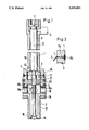
- FIG. 1 is an axial sectional view of a preferred embodiment of the invention.
- FIG. 2 is an enlarged view of inset A of FIG. 1.
- a circularly corrugated spring diaphragm 3 which hermetically separates a first chamber 4 from a fuel-filled second chamber 5.
- a clearance 6a formed between the facing edge portions of the housing parts 1 and 2 is closed in its radially outer zone by a circumferentially extending weld 6b and further, the housing portion 2 has, in a radially inner zone, a circumferentially extending rib 7 which presses the outer circumferential edge of the spring diaphragm 3 against the facing edge zone of the housing part 1.
- a piezoelectric stack actuator 8 of conventional construction and thus not described in further detail, electrical terminals 9 connected to the stack actuator 8 and an intermediate component 10 made of a material which ensures compensation of the heat-caused length variations of the stack actuator 8.
- the stack actuator 8 and the intermediate component 10 are received in the housing part 1 for sliding motion in a direction parallel to the housing axis 12.
- the upper end of the stack actuator 8 is countersupported by an adjusting screw 11 which sets the longitudinal position of the stack actuator 8 within the housing part 1.
- a pressure pin 13 is provided to engage a central area on one side of the spring diaphragm 3.
- a central area on the opposite side of the spring diaphragm 3 is connected with the upper end of the valve needle 14 while its opposite, lower end carries a valve head 15 to open or close the nozzle opening (metering aperture) 16.
- the lower housing part 2 which, by means of an external thread 17 and a sealing ring 18 may be screwed tightly into the wall of a combustion chamber of an internal combustion engine has, at the level of the second chamber 5, an annular groove 19 whose bottom is provided with a plurality of circumferentially spaced inlet ports 19a which open into the chamber 5 for charging the chamber 5 with pressurized fuel from a fuel line (not shown) coupled to the valve housing 2.
- a guide member 20 which is affixed to the inside of the housing part 2 and which has a central opening through which the upper, enlarged cylindrical part of the valve needle 14 slidably passes.
- the guide member 20 has at least one throughgoing port 21 to allow flow of fuel to the spring diaphragm 3 whereby the face of the latter oriented towards the second chamber 5 is exposed to fuel pressure.
- the piezoelectric stack actuator 8 Upon applying an electric voltage to the piezoelectric stack actuator 8, the latter expands in a direction parallel to the axis 12 while it is countersupported by the adjusting screw 11 so that, as a result, the valve needle 14 moves downwardly and the valve head 15 lifts off the nozzle opening 16.
- the downward movement of the valve needle 14 is accompanied by a downward deflection of the spring diaphragm 3.
- the piezoelectric staple actuator 8 assumes its original dimension whereupon the spring force of the spring diaphragm 3, in conjunction with the fuel pressure to which it is exposed, causes an upwardly oriented motion of the intermediate member 10 (in case it is not attached to the staple actuator 8), the pressure pin 13 as well as the valve needle 14 so that, as a result, the valve needle 14 assumes its position in which the valve head 15 closes the nozzle opening 16.
- the invention thus provides a metering valve in which the actuating member is, practically without additional structural complexities, hermetically sealed from the medium to be metered.
- a particular advantage of the invention resides in that the design and the mode of operation of the metering valve does not require compromises which would tend to adversely affect operation, efficiency or other properties of the metering valve. It is thus feasible, as shown in FIG. 1, to arrange the electric terminals 9 in a relatively cool zone of the metering valve so that electric insulations need not be highly heat-resistant.
Abstract
A fluid metering valve includes a housing; a nozzle opening; a spring diaphragm supported in the housing and hermetically dividing the inner space of the housing into a first chamber and a second chamber; an inlet provided in the housing for introducing pressurized fluid solely into the second chamber; and a valve needle slidably accommodated in the second chamber and having a closed position in which the valve needle maintains the nozzle opening closed and an open position in which the valve needle maintains the nozzle opening open. The valve needle is connected to the spring diaphragm and is resiliently urged by the spring diaphragm into the closed position. The metering valve further has a valve actuating member disposed in the first chamber and having an energized state and a de-energized state. The valve actuating member is connected to the valve needle for moving the valve needle into the open position against a force of the spring diaphragm when the valve actuating member is energized.
Description
This application claims the priority of Federal Republic of Germany Application No. P 39 06 184.1, filed Feb. 28th, 1989, which is incorporated herein by reference.
This invention relates to a metering valve, particularly a fuel injection valve for an internal combustion engine and is of the type which has a valve needle slidably supported in a valve housing and arranged to open or close at least one metering aperture (nozzle opening) communicating with a supply line in which the pressurized medium to be metered is advanced. The valve needle is actuated to move into its open position by an actuating member formed of a component which, under the effect of a field varies its dimension at least in one direction. The valve needle is returned into its closed position by spring force.
The above-outlined metering valve, apart from its use to inject fuel in a pulsating manner, may be used to meter other fluids such as liquids or gases including vapors.
In the direct injection of diesel fuel or gasoline into the work chambers of internal combustion engines, particularly those used for driving automotive vehicles - which is the preferred mode of application of the invention - the high-pressure injection has distinct advantages as compared to the conventional low-pressure injection into an intake (suction) pipe. These advantages manifest themselves particularly in the avoidance of hot-starting problems. In high-pressure injection the fuel is continuously available at correspondingly high pressure and the valve needle for opening the metering aperture (injection nozzle) is operated by introducing external energy. To achieve sharp actuating pulses of defined duration, piezoelectric devices or actuating assemblies operating according to the principle of magnetostriction have been used. These assemblies thus involve actuating members which vary their dimensions under the effect of an electric or magnetic field.
Thus, European Patent 218,895 describes a metering valve of the above-outlined type, used as a fuel injection valve, which in an axial sequence has a piezoelectric stack actuator, a guided force-transmitting pin and a valve needle. The valve needle terminates in a valve head which externally extends over the metering aperture (injection nozzle opening) for closing the same. The piezoelectric stack actuator is disposed in a housing chamber which is connected with a fuel supply and which constitutes a storage chamber for the fuel. For returning the valve needle into the closed position from the position in which it maintains the injection nozzle open, a coil spring is used which surrounds the valve needle and is compressed between a flange forming part of the valve needle and a countersupport forming part of the valve housing.
The accommodation of the actuating member in a fuel-filled chamber involves problems particularly in case the fuel contains water since, for example, in a piezoelectric actuating member voltages in the order of magnitude of 150 volts and higher may be present.
It is an object of the invention to provide an improved metering valve of the above-discussed type which, practically without rendering the structure more complex, eliminates problems which may be caused by arranging the valve needle actuating member in the medium to be metered.
This object and others to become apparent as the specification progresses, are accomplished by the invention, according to which, briefly stated, the spring force which returns the valve needle into its nozzle-closing position is generated by a spring diaphragm which, in the valve housing, hermetically separates a first chamber containing the actuating element from a second chamber containing the medium to be metered.
Thus, the invention is not limited to the teaching to arrange the actuating member in a chamber which is hermetically separated from the medium (for example, fuel) to be metered, but also provides that the septum required for such a hermetic separation assumes, as a spring diaphragm, the further function of a valve needle return spring which conventionally has been a separately provided spring member. Thus, according to the invention, the additional return spring may be dispensed with.
In view of the motion characteristics required of the spring diaphragm, the latter should have a relatively robust structure while taking into account that the movement of the valve needle into the closed position must be very rapid. A strong spring diaphragm may be utilized particularly when a piezoelectric actuating member is used because the latter may be readily so designed that it generates relatively large forces for effecting the opening motions of the valve needle.
According to a further feature of the invention, that surface of the spring diaphragm which is oriented towards the second chamber is exposed to the pressure of the medium to be metered. This arrangement permits to provide a spring diaphram that generates a relatively small spring force, since one part of the return force is supplied by the medium pressure.
FIG. 1 is an axial sectional view of a preferred embodiment of the invention.
FIG. 2 is an enlarged view of inset A of FIG. 1.
Turning to FIG. 1, between two housing portions 1 and 2 of a fuel injection valve there is clamped a circularly corrugated spring diaphragm 3 which hermetically separates a first chamber 4 from a fuel-filled second chamber 5. As particularly well seen in FIG. 2 a clearance 6a formed between the facing edge portions of the housing parts 1 and 2 is closed in its radially outer zone by a circumferentially extending weld 6b and further, the housing portion 2 has, in a radially inner zone, a circumferentially extending rib 7 which presses the outer circumferential edge of the spring diaphragm 3 against the facing edge zone of the housing part 1.
In the chamber 4 which is hermetically separated from the fuel by the spring diaphragm 3, there are disposed a piezoelectric stack actuator 8 of conventional construction and thus not described in further detail, electrical terminals 9 connected to the stack actuator 8 and an intermediate component 10 made of a material which ensures compensation of the heat-caused length variations of the stack actuator 8. The stack actuator 8 and the intermediate component 10 are received in the housing part 1 for sliding motion in a direction parallel to the housing axis 12. The upper end of the stack actuator 8 is countersupported by an adjusting screw 11 which sets the longitudinal position of the stack actuator 8 within the housing part 1. Further, in the first chamber 4, between the downwardly oriented end face of the intermediate part 10 and the spring diaphragm 3 a pressure pin 13 is provided to engage a central area on one side of the spring diaphragm 3. A central area on the opposite side of the spring diaphragm 3 is connected with the upper end of the valve needle 14 while its opposite, lower end carries a valve head 15 to open or close the nozzle opening (metering aperture) 16.
The lower housing part 2 which, by means of an external thread 17 and a sealing ring 18 may be screwed tightly into the wall of a combustion chamber of an internal combustion engine has, at the level of the second chamber 5, an annular groove 19 whose bottom is provided with a plurality of circumferentially spaced inlet ports 19a which open into the chamber 5 for charging the chamber 5 with pressurized fuel from a fuel line (not shown) coupled to the valve housing 2.
In the second chamber 5 there is further provided, at a distance from the spring diaphragm 3, a guide member 20 which is affixed to the inside of the housing part 2 and which has a central opening through which the upper, enlarged cylindrical part of the valve needle 14 slidably passes. The guide member 20 has at least one throughgoing port 21 to allow flow of fuel to the spring diaphragm 3 whereby the face of the latter oriented towards the second chamber 5 is exposed to fuel pressure.
Upon applying an electric voltage to the piezoelectric stack actuator 8, the latter expands in a direction parallel to the axis 12 while it is countersupported by the adjusting screw 11 so that, as a result, the valve needle 14 moves downwardly and the valve head 15 lifts off the nozzle opening 16. The downward movement of the valve needle 14 is accompanied by a downward deflection of the spring diaphragm 3. As soon as the electric voltage is removed or its polarity reversed, the piezoelectric staple actuator 8 assumes its original dimension whereupon the spring force of the spring diaphragm 3, in conjunction with the fuel pressure to which it is exposed, causes an upwardly oriented motion of the intermediate member 10 (in case it is not attached to the staple actuator 8), the pressure pin 13 as well as the valve needle 14 so that, as a result, the valve needle 14 assumes its position in which the valve head 15 closes the nozzle opening 16.
The invention thus provides a metering valve in which the actuating member is, practically without additional structural complexities, hermetically sealed from the medium to be metered. A particular advantage of the invention resides in that the design and the mode of operation of the metering valve does not require compromises which would tend to adversely affect operation, efficiency or other properties of the metering valve. It is thus feasible, as shown in FIG. 1, to arrange the electric terminals 9 in a relatively cool zone of the metering valve so that electric insulations need not be highly heat-resistant.
It will be understood that the above description of the present invention is susceptible to various modifications, changes and adaptations, and the same are intended to be comprehended within the meaning and range of equivalents of the appended claims.
Claims (6)
1. A fluid metering valve, comprising:
(a) a housing defining an inner space; said housing having a longitudinal axis;
(b) means defining a nozzle opening in said housing;
(c) a spring diaphragm supported in said housing and hermetically dividing said inner space into a first chamber and a second chamber; said nozzle opening being arranged to communicate with said second chamber; said spring diaphragm having a central region;
(d) means defining an inlet in said housing for introducing pressurized fluid solely into said second chamber;
(e) a valve needle slidably accommodated in said second chamber and having a closed position in which the valve needle maintains said nozzle opening closed and an open position in which the valve needle maintains said nozzle opening open; said valve needle having an end; said valve needle being operatively connected to said spring diaphragm by said end thereof and being resiliently urged by said spring diaphragm into the closed position; and
(f) a valve actuating member disposed in said first chamber and having an energized state and a de-energized state; said valve actuating member having an end facing and being in alignment with said end of said valve needle, said central region being situated between the facing ends of the valve actuating member and the valve needle and said end of said valve needle being attached to said central region, whereby said valve actuating member is operatively connected to said valve needle for moving the valve needle into said open position against a force of said spring diaphragm upon placement of said valve actuating member into said energized state.
2. A fluid metering valve as defined in claim 1, wherein said housing includes two axially adjoining housing parts; said spring diaphragm being clamped between the housing parts.
3. A fluid metering valve as defined in claim 1, further comprising a guide member situated in said second chamber and being secured to said housing; said guide member being situated at an axial distance from said spring diaphragm and having means for slidably guiding said valve needle.
4. A fluid metering valve as defined in claim 3, further wherein said guide member has a throughgoing port for admitting pressurized fluid to said spring diaphragm.
5. A fluid metering valve as defined in claim 1, wherein said means defining an inlet comprises an outer circumferential groove in said housing and an aperture provided in a bottom of the groove and merging into said second chamber.
6. A fluid metering valve as defined in claim 1, wherein said valve actuating member comprises a piezoelectric stack actuator.
Applications Claiming Priority (2)
| Application Number | Priority Date | Filing Date | Title |
|---|---|---|---|
| DE3906184 | 1989-02-28 | ||
| DE3906184 | 1989-02-28 |
Publications (1)
| Publication Number | Publication Date |
|---|---|
| US5031841A true US5031841A (en) | 1991-07-16 |
Family
ID=6375088
Family Applications (1)
| Application Number | Title | Priority Date | Filing Date |
|---|---|---|---|
| US07/480,055 Expired - Fee Related US5031841A (en) | 1989-02-28 | 1990-02-14 | Metering valve, particularly fuel injection valve |
Country Status (2)
| Country | Link |
|---|---|
| US (1) | US5031841A (en) |
| GB (1) | GB2228769B (en) |
Cited By (32)
| Publication number | Priority date | Publication date | Assignee | Title |
|---|---|---|---|---|
| EP0783644A1 (en) * | 1994-09-28 | 1997-07-16 | Tetra Laval Holdings & Finance SA | Dosing valve having seal failure detection |
| US5730417A (en) * | 1996-05-20 | 1998-03-24 | Regents Of The University Of California | Miniature piezo electric vacuum inlet valve |
| US5931390A (en) * | 1997-01-16 | 1999-08-03 | Daimler-Benz Ag | Valve for the dosed discharge of fluids |
| EP0964146A2 (en) * | 1998-06-09 | 1999-12-15 | Autogastechniek Holland B.V. | Metering valve and fuel supply system equipped therewith |
| US6019346A (en) * | 1998-03-06 | 2000-02-01 | Miller; Kenneth L. | Piezo-actuated high response valve |
| JP2001020823A (en) * | 1999-06-24 | 2001-01-23 | Robert Bosch Gmbh | Fuel injection valve |
| WO2001029400A2 (en) | 1999-10-15 | 2001-04-26 | Westport Research Inc. | Directly actuated injection valve |
| EP0872636A3 (en) * | 1997-04-18 | 2002-01-23 | Robert Bosch Gmbh | Fuel injection valve for internal combustion engines |
| US6464149B1 (en) | 1999-10-28 | 2002-10-15 | Delphi Technologies, Inc. | Actuator arrangement |
| WO2002084107A1 (en) * | 2001-04-14 | 2002-10-24 | Robert Bosch Gmbh | Piezoelectric actuator module |
| US6564777B2 (en) | 1999-10-15 | 2003-05-20 | Westport Research Inc. | Directly actuated injection valve with a composite needle |
| US6575138B2 (en) | 1999-10-15 | 2003-06-10 | Westport Research Inc. | Directly actuated injection valve |
| US6584958B2 (en) | 1999-10-15 | 2003-07-01 | Westport Research Inc. | Directly actuated injection valve with a ferromagnetic needle |
| US20030159735A1 (en) * | 2002-02-26 | 2003-08-28 | Cedrat Technologies | Piezoelectric valve |
| US6631883B1 (en) | 1998-06-09 | 2003-10-14 | Teleflex Gfi Europe B.V. | Metering valve and fuel supply system equipped therewith |
| WO2004016939A1 (en) * | 2002-07-20 | 2004-02-26 | Robert Bosch Gmbh | Piezoelectric actuator module and method for assembling a piezoelectric actuator module |
| US20050056706A1 (en) * | 2003-08-08 | 2005-03-17 | Crofts John D. | Piezoelectric control valve adjustment method |
| US6895130B1 (en) | 2002-02-12 | 2005-05-17 | Tobi Mengle | True position sensor for diaphragm valves using reflected light property variation |
| WO2005121542A1 (en) * | 2004-06-14 | 2005-12-22 | Westport Power Inc. | Valve with a pressurized hydraulic transmission device and a method of operating same |
| US20110155258A1 (en) * | 2008-07-18 | 2011-06-30 | Allpure Technologies, Inc. | Fluid transfer device |
| US8113179B1 (en) | 2010-08-10 | 2012-02-14 | Great Plains Diesel Technologies, L.C. | Programmable diesel fuel injector |
| US20120074245A1 (en) * | 2009-05-06 | 2012-03-29 | Ralph Engelberg | Device for injecting fuel |
| US8418676B2 (en) | 2010-08-10 | 2013-04-16 | Great Plains Diesel Technologies, L.C. | Programmable diesel fuel injector |
| US20130274760A1 (en) * | 2002-03-20 | 2013-10-17 | P Tech, Llc | Robotic fastening system |
| US8683982B2 (en) | 2010-08-10 | 2014-04-01 | Great Plains Diesel Technologies, L.C. | Programmable diesel fuel injector |
| US20150102241A1 (en) * | 2011-11-24 | 2015-04-16 | Robert Bosch Gmbh | Valve for metering in a flowing medium |
| US20150204275A1 (en) * | 2014-01-17 | 2015-07-23 | Robert Bosch Gmbh | Gas injector for the direct injection of gaseous fuel into a combustion chamber |
| US9385300B2 (en) | 2013-02-06 | 2016-07-05 | Great Plains Diesel Technologies, L.C. | Magnetostrictive actuator |
| US9568113B2 (en) | 2010-01-15 | 2017-02-14 | Allpure Technologies, Llc | Fluid transfer device |
| US20170320075A1 (en) * | 2015-04-21 | 2017-11-09 | Dresser, Inc. | Water injector nozzle |
| US9975753B1 (en) | 2017-04-26 | 2018-05-22 | Sartorius Stedim North America Inc. | Detachable fluid transfer device accessory and a fluid transfer assembly |
| US10058393B2 (en) | 2015-10-21 | 2018-08-28 | P Tech, Llc | Systems and methods for navigation and visualization |
Families Citing this family (5)
| Publication number | Priority date | Publication date | Assignee | Title |
|---|---|---|---|---|
| DE4306072C2 (en) * | 1993-02-26 | 1994-12-08 | Siemens Ag | Device for opening and closing a passage opening in a housing |
| DE19727992C2 (en) * | 1997-07-01 | 1999-05-20 | Siemens Ag | Compensation element for compensation of temperature-related changes in length of electromechanical control systems |
| DE19946603B4 (en) * | 1999-09-29 | 2009-01-15 | Robert Bosch Gmbh | Fuel injection valve with compensating sealing elements |
| US20110073071A1 (en) * | 2009-09-30 | 2011-03-31 | Woodward Governor Company | Internally Nested Variable-Area Fuel Nozzle |
| GB2549479A (en) * | 2016-04-18 | 2017-10-25 | Delphi Int Operations Luxembourg Sarl | Fuel injector |
Citations (7)
| Publication number | Priority date | Publication date | Assignee | Title |
|---|---|---|---|---|
| GB299532A (en) * | 1927-08-02 | 1928-11-01 | Marion Steam Shovel Co | Improvements relating to fuel atomisers for internal combustion engines and for other purposes |
| US3776263A (en) * | 1971-05-19 | 1973-12-04 | A Hubenthal | Fuel cut-off lock |
| EP0121028A1 (en) * | 1981-09-28 | 1984-10-10 | The Bendix Corporation | Direct liquid injection of liquid petroleum gas |
| US4669660A (en) * | 1985-01-15 | 1987-06-02 | Kernforschungszentrum Karlsruhe | Pulse valve |
| US4695034A (en) * | 1984-11-27 | 1987-09-22 | Stec Inc. | Fluid control device |
| GB2193386A (en) * | 1986-07-31 | 1988-02-03 | Toyota Motor Co Ltd | Piezoelectric actuator |
| US4725002A (en) * | 1985-09-17 | 1988-02-16 | Robert Bosch Gmbh | Measuring valve for dosing liquids or gases |
-
1990
- 1990-02-14 US US07/480,055 patent/US5031841A/en not_active Expired - Fee Related
- 1990-02-23 GB GB9004113A patent/GB2228769B/en not_active Expired - Fee Related
Patent Citations (7)
| Publication number | Priority date | Publication date | Assignee | Title |
|---|---|---|---|---|
| GB299532A (en) * | 1927-08-02 | 1928-11-01 | Marion Steam Shovel Co | Improvements relating to fuel atomisers for internal combustion engines and for other purposes |
| US3776263A (en) * | 1971-05-19 | 1973-12-04 | A Hubenthal | Fuel cut-off lock |
| EP0121028A1 (en) * | 1981-09-28 | 1984-10-10 | The Bendix Corporation | Direct liquid injection of liquid petroleum gas |
| US4695034A (en) * | 1984-11-27 | 1987-09-22 | Stec Inc. | Fluid control device |
| US4669660A (en) * | 1985-01-15 | 1987-06-02 | Kernforschungszentrum Karlsruhe | Pulse valve |
| US4725002A (en) * | 1985-09-17 | 1988-02-16 | Robert Bosch Gmbh | Measuring valve for dosing liquids or gases |
| GB2193386A (en) * | 1986-07-31 | 1988-02-03 | Toyota Motor Co Ltd | Piezoelectric actuator |
Cited By (67)
| Publication number | Priority date | Publication date | Assignee | Title |
|---|---|---|---|---|
| EP0783644A1 (en) * | 1994-09-28 | 1997-07-16 | Tetra Laval Holdings & Finance SA | Dosing valve having seal failure detection |
| EP0783644B1 (en) * | 1994-09-28 | 2002-12-11 | Tetra Laval Holdings & Finance SA | Dosing valve having seal failure detection |
| US5730417A (en) * | 1996-05-20 | 1998-03-24 | Regents Of The University Of California | Miniature piezo electric vacuum inlet valve |
| US5931390A (en) * | 1997-01-16 | 1999-08-03 | Daimler-Benz Ag | Valve for the dosed discharge of fluids |
| EP0872636A3 (en) * | 1997-04-18 | 2002-01-23 | Robert Bosch Gmbh | Fuel injection valve for internal combustion engines |
| US6019346A (en) * | 1998-03-06 | 2000-02-01 | Miller; Kenneth L. | Piezo-actuated high response valve |
| AU743884B2 (en) * | 1998-06-09 | 2002-02-07 | Teleflex Gfi Europe B.V. | Metering valve and fuel supply system equipped therewith |
| EP0964146A2 (en) * | 1998-06-09 | 1999-12-15 | Autogastechniek Holland B.V. | Metering valve and fuel supply system equipped therewith |
| WO1999064773A1 (en) * | 1998-06-09 | 1999-12-16 | Autogastechniek Holland B.V. | Metering valve and fuel supply system equipped therewith |
| EP0964146A3 (en) * | 1998-06-09 | 2000-12-13 | Autogastechniek Holland B.V. | Metering valve and fuel supply system equipped therewith |
| US6631883B1 (en) | 1998-06-09 | 2003-10-14 | Teleflex Gfi Europe B.V. | Metering valve and fuel supply system equipped therewith |
| US6425376B1 (en) * | 1999-06-24 | 2002-07-30 | Robert Bosch Gmbh | Fuel injector |
| JP2001020823A (en) * | 1999-06-24 | 2001-01-23 | Robert Bosch Gmbh | Fuel injection valve |
| JP4499250B2 (en) * | 1999-06-24 | 2010-07-07 | ローベルト ボツシユ ゲゼルシヤフト ミツト ベシユレンクテル ハフツング | Fuel injection valve |
| US6298829B1 (en) | 1999-10-15 | 2001-10-09 | Westport Research Inc. | Directly actuated injection valve |
| US6564777B2 (en) | 1999-10-15 | 2003-05-20 | Westport Research Inc. | Directly actuated injection valve with a composite needle |
| US6575138B2 (en) | 1999-10-15 | 2003-06-10 | Westport Research Inc. | Directly actuated injection valve |
| US6584958B2 (en) | 1999-10-15 | 2003-07-01 | Westport Research Inc. | Directly actuated injection valve with a ferromagnetic needle |
| WO2001029400A2 (en) | 1999-10-15 | 2001-04-26 | Westport Research Inc. | Directly actuated injection valve |
| US6464149B1 (en) | 1999-10-28 | 2002-10-15 | Delphi Technologies, Inc. | Actuator arrangement |
| WO2002084107A1 (en) * | 2001-04-14 | 2002-10-24 | Robert Bosch Gmbh | Piezoelectric actuator module |
| US6962297B2 (en) | 2001-04-14 | 2005-11-08 | Robert Bosch Gmbh | Piezoelectric actuator module |
| US6895130B1 (en) | 2002-02-12 | 2005-05-17 | Tobi Mengle | True position sensor for diaphragm valves using reflected light property variation |
| US6994110B2 (en) * | 2002-02-26 | 2006-02-07 | Cedrat Technologies | Piezoelectric valve |
| US20030159735A1 (en) * | 2002-02-26 | 2003-08-28 | Cedrat Technologies | Piezoelectric valve |
| US9629687B2 (en) | 2002-03-20 | 2017-04-25 | P Tech, Llc | Robotic arthroplasty system |
| US9271741B2 (en) | 2002-03-20 | 2016-03-01 | P Tech, Llc | Robotic ultrasonic energy system |
| US9877793B2 (en) | 2002-03-20 | 2018-01-30 | P Tech, Llc | Robotic arthroplasty system |
| US9585725B2 (en) | 2002-03-20 | 2017-03-07 | P Tech, Llc | Robotic arthroplasty system |
| US9486227B2 (en) | 2002-03-20 | 2016-11-08 | P Tech, Llc | Robotic retractor system |
| US10265128B2 (en) | 2002-03-20 | 2019-04-23 | P Tech, Llc | Methods of using a robotic spine system |
| US10959791B2 (en) | 2002-03-20 | 2021-03-30 | P Tech, Llc | Robotic surgery |
| US9808318B2 (en) | 2002-03-20 | 2017-11-07 | P Tech, Llc | Robotic arthroplasty system |
| US10932869B2 (en) | 2002-03-20 | 2021-03-02 | P Tech, Llc | Robotic surgery |
| US20130274760A1 (en) * | 2002-03-20 | 2013-10-17 | P Tech, Llc | Robotic fastening system |
| US9271779B2 (en) | 2002-03-20 | 2016-03-01 | P Tech, Llc | Methods of using a robotic spine system |
| US9192395B2 (en) * | 2002-03-20 | 2015-11-24 | P Tech, Llc | Robotic fastening system |
| US9155544B2 (en) | 2002-03-20 | 2015-10-13 | P Tech, Llc | Robotic systems and methods |
| US10869728B2 (en) | 2002-03-20 | 2020-12-22 | P Tech, Llc | Robotic surgery |
| US10368953B2 (en) | 2002-03-20 | 2019-08-06 | P Tech, Llc | Robotic system for fastening layers of body tissue together and method thereof |
| US9149281B2 (en) | 2002-03-20 | 2015-10-06 | P Tech, Llc | Robotic system for engaging a fastener with body tissue |
| WO2004016939A1 (en) * | 2002-07-20 | 2004-02-26 | Robert Bosch Gmbh | Piezoelectric actuator module and method for assembling a piezoelectric actuator module |
| US20050056706A1 (en) * | 2003-08-08 | 2005-03-17 | Crofts John D. | Piezoelectric control valve adjustment method |
| US6971172B2 (en) | 2003-08-08 | 2005-12-06 | Cummins Inc. | Piezoelectric control valve adjustment method |
| WO2005121542A1 (en) * | 2004-06-14 | 2005-12-22 | Westport Power Inc. | Valve with a pressurized hydraulic transmission device and a method of operating same |
| CN1977105B (en) * | 2004-06-14 | 2010-09-29 | 西港能源公司 | Valve with a pressurized hydraulic transmission device and a method of operating same |
| US8613422B2 (en) * | 2008-07-18 | 2013-12-24 | Allpure Technologies, Inc. | Fluid transfer device |
| US20110155258A1 (en) * | 2008-07-18 | 2011-06-30 | Allpure Technologies, Inc. | Fluid transfer device |
| US8960573B2 (en) * | 2009-05-06 | 2015-02-24 | Robert Bosch Gmbh | Device for injecting fuel |
| US20120074245A1 (en) * | 2009-05-06 | 2012-03-29 | Ralph Engelberg | Device for injecting fuel |
| US9568113B2 (en) | 2010-01-15 | 2017-02-14 | Allpure Technologies, Llc | Fluid transfer device |
| US8683982B2 (en) | 2010-08-10 | 2014-04-01 | Great Plains Diesel Technologies, L.C. | Programmable diesel fuel injector |
| US8113179B1 (en) | 2010-08-10 | 2012-02-14 | Great Plains Diesel Technologies, L.C. | Programmable diesel fuel injector |
| US8418676B2 (en) | 2010-08-10 | 2013-04-16 | Great Plains Diesel Technologies, L.C. | Programmable diesel fuel injector |
| US9822750B2 (en) * | 2011-11-24 | 2017-11-21 | Robert Bosch Gmbh | Valve for metering in a flowing medium |
| US20150102241A1 (en) * | 2011-11-24 | 2015-04-16 | Robert Bosch Gmbh | Valve for metering in a flowing medium |
| US9385300B2 (en) | 2013-02-06 | 2016-07-05 | Great Plains Diesel Technologies, L.C. | Magnetostrictive actuator |
| US20150204275A1 (en) * | 2014-01-17 | 2015-07-23 | Robert Bosch Gmbh | Gas injector for the direct injection of gaseous fuel into a combustion chamber |
| US9810179B2 (en) * | 2014-01-17 | 2017-11-07 | Robert Bosch Gmbh | Gas injector for the direct injection of gaseous fuel into a combustion chamber |
| US20170320075A1 (en) * | 2015-04-21 | 2017-11-09 | Dresser, Inc. | Water injector nozzle |
| US11285497B2 (en) * | 2015-04-21 | 2022-03-29 | Dresser, Llc | Water injector nozzle |
| US10765484B2 (en) | 2015-10-21 | 2020-09-08 | P Tech, Llc | Systems and methods for navigation and visualization |
| US10058393B2 (en) | 2015-10-21 | 2018-08-28 | P Tech, Llc | Systems and methods for navigation and visualization |
| US11317974B2 (en) | 2015-10-21 | 2022-05-03 | P Tech, Llc | Systems and methods for navigation and visualization |
| US11684430B2 (en) | 2015-10-21 | 2023-06-27 | P Tech, Llc | Systems and methods for navigation and visualization |
| US11744651B2 (en) | 2015-10-21 | 2023-09-05 | P Tech, Llc | Systems and methods for navigation and visualization |
| US9975753B1 (en) | 2017-04-26 | 2018-05-22 | Sartorius Stedim North America Inc. | Detachable fluid transfer device accessory and a fluid transfer assembly |
Also Published As
| Publication number | Publication date |
|---|---|
| GB2228769B (en) | 1993-10-06 |
| GB9004113D0 (en) | 1990-04-18 |
| GB2228769A (en) | 1990-09-05 |
Similar Documents
| Publication | Publication Date | Title |
|---|---|---|
| US5031841A (en) | Metering valve, particularly fuel injection valve | |
| US4725002A (en) | Measuring valve for dosing liquids or gases | |
| US5169067A (en) | Electromagnetically operated ultrasonic fuel injection device | |
| JP5304861B2 (en) | Fuel injection device | |
| US4909440A (en) | Fuel injector for an engine | |
| KR20000015898A (en) | Fuel injection valve with a piezo-electric or magnetostrictive actuator | |
| US4972996A (en) | Dual lift electromagnetic fuel injector | |
| US20040164175A1 (en) | Fuel-injection valve | |
| JP2002525486A (en) | Fuel injection valve | |
| US4917352A (en) | Injector for engine with spark ignition and direct injection | |
| US5518184A (en) | Fuel injection nozzle for internal combustion engines | |
| JP2002525487A (en) | Fuel injection valve | |
| JPH0223753B2 (en) | ||
| US4690374A (en) | Magnetic valve for fluid control | |
| JP3539959B2 (en) | Fuel injection device for internal combustion engine | |
| US11346307B2 (en) | Fluid injector and needle for a fluid injector | |
| US20190309717A1 (en) | Valve Assembly for an Injection Valve | |
| US6637677B1 (en) | Fuel injector | |
| EP2011998B1 (en) | Fuel pump for internal combustion engine | |
| KR20020029409A (en) | Fuel injection valve | |
| US5100102A (en) | Compact electronic fuel injector | |
| KR20050027047A (en) | Fuel injection valve | |
| KR20020019555A (en) | Fuel injection valve | |
| KR890002535A (en) | Fuel injection nozzles of internal combustion engines | |
| US6435429B1 (en) | Fuel injection valve |
Legal Events
| Date | Code | Title | Description |
|---|---|---|---|
| AS | Assignment |
Owner name: VOLKSWAGEN AG, GERMANY Free format text: ASSIGNMENT OF ASSIGNORS INTEREST.;ASSIGNOR:SCHAFER, HANS-JURGEN;REEL/FRAME:005248/0075 Effective date: 19900123 |
|
| REMI | Maintenance fee reminder mailed | ||
| LAPS | Lapse for failure to pay maintenance fees | ||
| FP | Lapsed due to failure to pay maintenance fee |
Effective date: 19950719 |
|
| STCH | Information on status: patent discontinuation |
Free format text: PATENT EXPIRED DUE TO NONPAYMENT OF MAINTENANCE FEES UNDER 37 CFR 1.362 |