US5042909A - Real time three dimensional display with angled rotating screen and method - Google Patents
Real time three dimensional display with angled rotating screen and method Download PDFInfo
- Publication number
- US5042909A US5042909A US07/584,413 US58441390A US5042909A US 5042909 A US5042909 A US 5042909A US 58441390 A US58441390 A US 58441390A US 5042909 A US5042909 A US 5042909A
- Authority
- US
- United States
- Prior art keywords
- light beam
- display
- display system
- set forth
- image
- Prior art date
- Legal status (The legal status is an assumption and is not a legal conclusion. Google has not performed a legal analysis and makes no representation as to the accuracy of the status listed.)
- Expired - Fee Related
Links
Images
Classifications
-
- H—ELECTRICITY
- H04—ELECTRIC COMMUNICATION TECHNIQUE
- H04N—PICTORIAL COMMUNICATION, e.g. TELEVISION
- H04N13/00—Stereoscopic video systems; Multi-view video systems; Details thereof
- H04N13/30—Image reproducers
- H04N13/388—Volumetric displays, i.e. systems where the image is built up from picture elements distributed through a volume
- H04N13/393—Volumetric displays, i.e. systems where the image is built up from picture elements distributed through a volume the volume being generated by a moving, e.g. vibrating or rotating, surface
-
- G—PHYSICS
- G02—OPTICS
- G02B—OPTICAL ELEMENTS, SYSTEMS OR APPARATUS
- G02B30/00—Optical systems or apparatus for producing three-dimensional [3D] effects, e.g. stereoscopic images
- G02B30/50—Optical systems or apparatus for producing three-dimensional [3D] effects, e.g. stereoscopic images the image being built up from image elements distributed over a 3D volume, e.g. voxels
- G02B30/54—Optical systems or apparatus for producing three-dimensional [3D] effects, e.g. stereoscopic images the image being built up from image elements distributed over a 3D volume, e.g. voxels the 3D volume being generated by moving a 2D surface, e.g. by vibrating or rotating the 2D surface
-
- H—ELECTRICITY
- H04—ELECTRIC COMMUNICATION TECHNIQUE
- H04N—PICTORIAL COMMUNICATION, e.g. TELEVISION
- H04N13/00—Stereoscopic video systems; Multi-view video systems; Details thereof
- H04N13/30—Image reproducers
- H04N13/363—Image reproducers using image projection screens
-
- H—ELECTRICITY
- H04—ELECTRIC COMMUNICATION TECHNIQUE
- H04N—PICTORIAL COMMUNICATION, e.g. TELEVISION
- H04N13/00—Stereoscopic video systems; Multi-view video systems; Details thereof
- H04N13/10—Processing, recording or transmission of stereoscopic or multi-view image signals
-
- H—ELECTRICITY
- H04—ELECTRIC COMMUNICATION TECHNIQUE
- H04N—PICTORIAL COMMUNICATION, e.g. TELEVISION
- H04N13/00—Stereoscopic video systems; Multi-view video systems; Details thereof
- H04N13/30—Image reproducers
- H04N13/398—Synchronisation thereof; Control thereof
Definitions
- This invention relates to a three dimensional display system and, more specifically, to a system capable of displaying images on a screen in three dimensions wherein one or more such images can be projected in two dimensions from either the same side of the screen or from opposite sides thereof.
- Prior art three dimensional display techniques were limited because of their use with CRT screens in that the produced image may be viewed only from selected angles. Moreover, such prior art systems have generally not been able to produce real time images and have been limited in the possible vibration frequencies of the screens. Moreover, the use of vibrating mirrors has created difficulties due to the relatively large mass of the mirrors which prevent substantial deflections. For example, such prior art systems have generally been capable of providing a mirror displacement of about 0.4 millimeters.
- a system which solved this problem is disclosed in Sher U.S. Pat. No. 4,130,832 wherein the three dimensional display includes a laser which directs a beam of light toward a mirror, the mirror being moved In an X-Y plane by piezoelectric transducers. The reflected light beam is directed to a vibrating screen which is moved by a piezoelectric transducer to form a three dimensional image.
- This system while providing the desired result, is limited as to the size of the image displayed since the screen and image size are determined by the size of the piezoelectric transducer.
- the above noted problems of the prior art are minimized and there is provided a three dimensional display system which is not substantially affected by G forces and wherein the size of the displayed image and screen is determined by the size of a disk and motor.
- the system in accordance with the present invention can be used, for example, in business and industry uses, such as solid animation, radar display, molecular research, resonant frequency and harmonics display, military, computer graphics and the like.
- the system in accordance with a first embodiment thereof includes a disk-like screen connected to the end of a motor shaft.
- the disk is attached to the shaft of a motor at a 45 degree angle, though this angle can be varied to provide a larger or smaller height or z-axis dimension, so that, as the disk rotates, a displacement of any given point thereon along the z axis takes place.
- the image is formed on the screen by projecting a light beam, such as from a laser, through a modulator and toward a scanner which produces an x-y scan of the beam on a screen, the screen herein being the disk discussed hereinabove.
- the disk can be translucent, such as lucite, so that images can be projected thereon onto the front and/or rear surfaces thereof
- the modulation or strobing of the scan is then synchronized with the rotating disk by control of the motor speed so that a three dimensional pattern appears on the screen. It can be seen that any point on the x-y scan from the scanner which impinges upon the screen will move along a z-axis direction since the screen or disk at that point produces such z-axis movement. This movement of the displayed image provides the three dimensional effect.
- the adjustment of the angle between the disk surface and the x-y plane of the scanned x-y image will determine the z dimension or height of the three dimensional image, the disk angle being adjustable on-line, if so desired.
- the disk herein is a planar opaque screen for receiving a scanned image thereon on one surface thereof
- the screen can take many other forms.
- the disk can be translucent, such as lucite, and thereby capable of receiving a scanned image therein on both major surfaces.
- the lucite disk can be in the form of a pair of angularly truncated cylinders with the same which fit together at the angularly truncated surfaces to form a net cylinder wherein the surfaces at which truncation takes place are translucent.
- the screen can take on shapes other than planar, it merely being necessary that at least some portion thereof move in the z direction during rotation thereof while projection of the x-y image thereon takes place to provide the three dimensional image.
- the disk can be placed in a gas filled or evacuated CRT with the image impinging thereon being the scanned beam of the tube. Phosphors can be disposed on the disk which, when excited, will form the three dimensional image.
- the screen can be planar and disposed normal to the projected x-y image. The three dimensional affect is then provided by moving the entire screen along the z-axis in synchronism with the scanned x-y image to provide the three dimensional affect.
- a cam driven shaft attached to the screen can provide such screen movement along the z-axis.
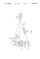
- FIG. 1 is a schematic diagram of a three dimensional display system utilizing a screen in accordance with the present invention.
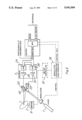
- FIG. 2 is a circuit diagram showing synchronization of the scanner with the rotation of the display screen.
- FIG. 1 there is shown a schematic diagram of a system in accordance with the present invention.
- the system includes a laser 7 which projects a light beam through a modulator 4 onto an x-y scanner 5.
- the modulator 4 is externally controlled in predetermined manner (not shown) to control the intensity of the laser light beam 3 passing therethrough. It is understood that the light intensity can be controlled so that no light passes through the modulator, when so desired.
- the x-y scanner whose scanning rate is externally controllable in standard manner (not shown), scans the light beam 3 from the modulator along an x-y plane and projects this x-y image 6 onto a screen 1 in the form of a disk as will be explained hereinbelow. All of the structure described to this point except for the particular screen and its operation is well known and described in the above noted prior art and elsewhere.
- the screen 1 is rotated by a motor 8 via a shaft motor 2, the motor speed being controllable by means of a controller (not shown).
- the motor speed is preferably synchronized with the scanning rate of the scanner 5.
- One typical circuit for providing such synchronization is shown in FIG. 2 so that the same spot on the disk is always present to receive a particular part of the x-y scan projected thereon. The circuit of FIG. 2 will be explained hereinbelow.
- the screen 1 can be a standard type movie screen if it is to be viewed from only one side thereof, as for the system described herein thus far.
- the screen angle is preferably 45 degrees with respect to the image received from the scanner. However, this angle can be altered about 45 degrees in either direction, the effect of such angle alteration being to vary the height or z-dimension of the displayed image with continued change in such angle.
- the screen angle is variable on line, it so desired, by a structure (not shown) of known type which rotates the mirror on the shaft 2.
- the scanner 5 is controlled by signals on the GSI scanner bus which are which are derived from the control bus.
- the signals on the control bus are provided by the synchronizing user circuitry which can be manually controlled, such as by the control input thereto.
- the circuitry 36 also controls the motor controller 32 to control the speed of the motor 8.
- the circuitry 36 can also control the modulator 4 via modulator control circuitry 34.
- Such circuitry is well known.
- the scanner 5 includes a digital to analog converter 24 which provides a Y-axis signal via amplifier 26 and a digital to analog converter 28 which provides an X-axis signal via amplifier 30.
- the signals from amplifiers 26 and 30 control x-axis and y-axis scanning devices 20 and 22 respectively which position a mirror 42 which reflects the modulated light beam from the laser 7.
- a light beam from the laser 7 is modulated by the externally controllable modulator 4 to provide a modulated beam 3 which strikes the x-y scanner 5, the latter having an externally controllable scanning rate as determined by signals on the GSI scanner bus and the control bus of FIG. 2.
- the scanner 5 scans the light beam in an x-y plane via the mirror 42 onto the rotating screen 1, the speed of rotation of the screen 1 being synchronized to the scanning rate of the scanner 5 as explained hereinabove.
- any point of light in the x-y plane impinging upon the screen 1 will display a harmonic type motion in the z-plane due to the similar movement of points on the screen.
- the system above described is duplicated except that the screen 1 is translucent to permit viewing therethrough.
- images in three dimensions can be provided on both sides of the screen.
- the second system operates in the same manner as does the system already described and projects the scanned image in a second x-y plane against the rear surface of the translucent screen 1. This image will move in the z-direction in the same manner as above described except that it will be disposed behind the screen.
- both images will be visible in three dimensions from either side of the screen.
Abstract
Description
Claims (55)
Priority Applications (2)
| Application Number | Priority Date | Filing Date | Title |
|---|---|---|---|
| US07/409,176 US5082350A (en) | 1987-10-07 | 1989-09-19 | Real time three dimensional display system for displaying images in three dimensions which are projected onto a screen in two dimensions |
| US07/584,413 US5042909A (en) | 1987-10-07 | 1990-09-17 | Real time three dimensional display with angled rotating screen and method |
Applications Claiming Priority (3)
| Application Number | Priority Date | Filing Date | Title |
|---|---|---|---|
| US10592487A | 1987-10-07 | 1987-10-07 | |
| US39047389A | 1989-08-03 | 1989-08-03 | |
| US07/584,413 US5042909A (en) | 1987-10-07 | 1990-09-17 | Real time three dimensional display with angled rotating screen and method |
Related Parent Applications (1)
| Application Number | Title | Priority Date | Filing Date |
|---|---|---|---|
| US39047389A Continuation | 1987-10-07 | 1989-08-03 |
Related Child Applications (1)
| Application Number | Title | Priority Date | Filing Date |
|---|---|---|---|
| US07/409,176 Continuation-In-Part US5082350A (en) | 1987-10-07 | 1989-09-19 | Real time three dimensional display system for displaying images in three dimensions which are projected onto a screen in two dimensions |
Publications (1)
| Publication Number | Publication Date |
|---|---|
| US5042909A true US5042909A (en) | 1991-08-27 |
Family
ID=27380004
Family Applications (1)
| Application Number | Title | Priority Date | Filing Date |
|---|---|---|---|
| US07/584,413 Expired - Fee Related US5042909A (en) | 1987-10-07 | 1990-09-17 | Real time three dimensional display with angled rotating screen and method |
Country Status (1)
| Country | Link |
|---|---|
| US (1) | US5042909A (en) |
Cited By (26)
| Publication number | Priority date | Publication date | Assignee | Title |
|---|---|---|---|---|
| US5157546A (en) * | 1990-12-19 | 1992-10-20 | Texas Instruments Incorporated | Volume display system and method for inside-out viewing |
| US5162787A (en) * | 1989-02-27 | 1992-11-10 | Texas Instruments Incorporated | Apparatus and method for digitized video system utilizing a moving display surface |
| US5231538A (en) * | 1991-08-07 | 1993-07-27 | Texas Instruments Incorporated | Volume display optical system and method |
| US5418632A (en) * | 1994-01-21 | 1995-05-23 | Texas Instruments Incorporated | System and method for rotational scanner based volume display |
| EP0758778A2 (en) * | 1995-08-11 | 1997-02-19 | Sharp Kabushiki Kaisha | Three-dimensional image display device |
| US5754147A (en) * | 1993-08-18 | 1998-05-19 | Tsao; Che-Chih | Method and apparatus for displaying three-dimensional volumetric images |
| US5854613A (en) * | 1994-03-16 | 1998-12-29 | The United Sates Of America As Represented By The Secretary Of The Navy | Laser based 3D volumetric display system |
| US5867152A (en) * | 1994-03-22 | 1999-02-02 | Raytheon Ti Systems, Inc. | On-line laser alignment system for three dimensional display |
| US5926294A (en) * | 1995-12-12 | 1999-07-20 | Sharp Kabushiki Kaisha | Three-dimensional image display device having an elementary hologram panel and method for manufacturing the elementary hologram panel |
| US5936767A (en) * | 1996-03-18 | 1999-08-10 | Yale University | Multiplanar autostereoscopic imaging system |
| US5944403A (en) * | 1996-11-15 | 1999-08-31 | Krause; Detlef | Virtual image projection device |
| US6005608A (en) * | 1996-05-06 | 1999-12-21 | The University Of Kansas | Three-dimensional display apparatus |
| US6052100A (en) * | 1994-03-16 | 2000-04-18 | The United States Of America Represented By The Secertary Of The Navy | Computer controlled three-dimensional volumetric display |
| US6064423A (en) * | 1998-02-12 | 2000-05-16 | Geng; Zheng Jason | Method and apparatus for high resolution three dimensional display |
| US6183088B1 (en) | 1998-05-27 | 2001-02-06 | Actuality Systems, Inc. | Three-dimensional display system |
| US6364490B1 (en) | 1996-11-15 | 2002-04-02 | Vantage Lighting Incorporated | Virtual image projection device |
| US6512498B1 (en) | 1999-06-21 | 2003-01-28 | Actuality Systems, Inc. | Volumetric stroboscopic display |
| US6646623B1 (en) | 1999-06-01 | 2003-11-11 | The University Of Kansas | Three-dimensional display apparatus |
| US20040095973A1 (en) * | 1995-06-02 | 2004-05-20 | Kazuhisa Yamamoto | Optical device, laser beam source, laser apparatus and method of producing optical device |
| US6765566B1 (en) | 1998-12-22 | 2004-07-20 | Che-Chih Tsao | Method and apparatus for displaying volumetric 3D images |
| US20060017727A1 (en) * | 2004-07-26 | 2006-01-26 | Che-Chih Tsao | Methods of displaying volumetric 3D images |
| DE102006044989A1 (en) * | 2006-09-23 | 2008-04-10 | Arctos Showlasertechnik E.Kfm. | Laser device for generating three-dimensional light objects in a volume containing a scattering medium |
| US20090005961A1 (en) * | 2004-06-03 | 2009-01-01 | Making Virtual Solid, L.L.C. | En-Route Navigation Display Method and Apparatus Using Head-Up Display |
| US20090167638A1 (en) * | 2007-12-27 | 2009-07-02 | Sang Gon Lee | Flexible film and display device comprising the same |
| CN101800906B (en) * | 2009-02-11 | 2011-11-16 | 中国科学院自动化研究所 | True three-dimensional imaging display screen |
| CN105867096A (en) * | 2016-04-28 | 2016-08-17 | 青岛奇异果智能科技有限公司 | High-speed rotary optical medium based three-dimensional holographic laser projection system |
Citations (7)
| Publication number | Priority date | Publication date | Assignee | Title |
|---|---|---|---|---|
| US3140415A (en) * | 1960-06-16 | 1964-07-07 | Hughes Aircraft Co | Three-dimensional display cathode ray tube |
| US3583784A (en) * | 1970-06-17 | 1971-06-08 | Us Navy | Hologram manipulator |
| US3956833A (en) * | 1974-09-13 | 1976-05-18 | The United States Of America As Represented By The United States National Aeronautics And Space Administration | Vehicle simulator binocular multiplanar visual display system |
| JPS5674219A (en) * | 1979-11-22 | 1981-06-19 | Victor Co Of Japan Ltd | Three-dimensional display device |
| JPS60257695A (en) * | 1984-06-04 | 1985-12-19 | Yasushi Maki | Stereoscopic video image generating device |
| US4871231A (en) * | 1987-10-16 | 1989-10-03 | Texas Instruments Incorporated | Three dimensional color display and system |
| US4922336A (en) * | 1989-09-11 | 1990-05-01 | Eastman Kodak Company | Three dimensional display system |
-
1990
- 1990-09-17 US US07/584,413 patent/US5042909A/en not_active Expired - Fee Related
Patent Citations (7)
| Publication number | Priority date | Publication date | Assignee | Title |
|---|---|---|---|---|
| US3140415A (en) * | 1960-06-16 | 1964-07-07 | Hughes Aircraft Co | Three-dimensional display cathode ray tube |
| US3583784A (en) * | 1970-06-17 | 1971-06-08 | Us Navy | Hologram manipulator |
| US3956833A (en) * | 1974-09-13 | 1976-05-18 | The United States Of America As Represented By The United States National Aeronautics And Space Administration | Vehicle simulator binocular multiplanar visual display system |
| JPS5674219A (en) * | 1979-11-22 | 1981-06-19 | Victor Co Of Japan Ltd | Three-dimensional display device |
| JPS60257695A (en) * | 1984-06-04 | 1985-12-19 | Yasushi Maki | Stereoscopic video image generating device |
| US4871231A (en) * | 1987-10-16 | 1989-10-03 | Texas Instruments Incorporated | Three dimensional color display and system |
| US4922336A (en) * | 1989-09-11 | 1990-05-01 | Eastman Kodak Company | Three dimensional display system |
Non-Patent Citations (2)
| Title |
|---|
| "Investigation of a 3D Display Using Optical Fiber Sheets"; Yamada et al.; Gazodenshigakkaishi, vol. 16, #6, pp. 372-379; May '87. |
| Investigation of a 3D Display Using Optical Fiber Sheets ; Yamada et al.; Gazodenshigakkaishi, vol. 16, 6, pp. 372 379; May 87. * |
Cited By (46)
| Publication number | Priority date | Publication date | Assignee | Title |
|---|---|---|---|---|
| US5162787A (en) * | 1989-02-27 | 1992-11-10 | Texas Instruments Incorporated | Apparatus and method for digitized video system utilizing a moving display surface |
| US5157546A (en) * | 1990-12-19 | 1992-10-20 | Texas Instruments Incorporated | Volume display system and method for inside-out viewing |
| US5606454A (en) * | 1990-12-19 | 1997-02-25 | Texas Instruments Incorporated | Volume display system and method for inside-out viewing |
| US5231538A (en) * | 1991-08-07 | 1993-07-27 | Texas Instruments Incorporated | Volume display optical system and method |
| US5754147A (en) * | 1993-08-18 | 1998-05-19 | Tsao; Che-Chih | Method and apparatus for displaying three-dimensional volumetric images |
| US5418632A (en) * | 1994-01-21 | 1995-05-23 | Texas Instruments Incorporated | System and method for rotational scanner based volume display |
| US6052100A (en) * | 1994-03-16 | 2000-04-18 | The United States Of America Represented By The Secertary Of The Navy | Computer controlled three-dimensional volumetric display |
| US5854613A (en) * | 1994-03-16 | 1998-12-29 | The United Sates Of America As Represented By The Secretary Of The Navy | Laser based 3D volumetric display system |
| US5867152A (en) * | 1994-03-22 | 1999-02-02 | Raytheon Ti Systems, Inc. | On-line laser alignment system for three dimensional display |
| US20080107140A1 (en) * | 1995-06-02 | 2008-05-08 | Matsushita Electric Industrial Co., Ltd. | Optical device, laser beam source, laser apparatus and method of producing optical device |
| US7101723B2 (en) | 1995-06-02 | 2006-09-05 | Matsushita Electric Industrial Co., Ltd. | Optical device, laser beam source, laser apparatus and method of producing optical device |
| US20080123700A1 (en) * | 1995-06-02 | 2008-05-29 | Matsushita Electric Industrial Co., Ltd. | Optical device, laser beam source, laser apparatus and method of producing optical device |
| US7570677B2 (en) | 1995-06-02 | 2009-08-04 | Panasonic Corporation | Optical device, laser beam source, laser apparatus and method of producing optical device |
| US7339960B2 (en) | 1995-06-02 | 2008-03-04 | Matsushita Electric Industrial Co., Ltd. | Optical device, laser beam source, laser apparatus and method of producing optical device |
| CN100351670C (en) * | 1995-06-02 | 2007-11-28 | 松下电器产业株式会社 | Optical element, laser light source, laser device and method for mfg. optical element |
| US7295583B2 (en) | 1995-06-02 | 2007-11-13 | Matsushita Electric Industrial Co., Ltd. | Optical device, laser beam source, laser apparatus and method of producing optical device |
| US7382811B2 (en) | 1995-06-02 | 2008-06-03 | Matsushita Electric Industrial Co., Ltd. | Optical device, laser beam source, laser apparatus and method of producing optical device |
| US7623559B2 (en) | 1995-06-02 | 2009-11-24 | Panasonic Corporation | Optical device, laser beam source, laser apparatus and method of producing optical device |
| US20040105469A1 (en) * | 1995-06-02 | 2004-06-03 | Kazuhisa Yamamoto | Optical device, laser beam source, laser apparatus and method of producing optical device |
| US20040095972A1 (en) * | 1995-06-02 | 2004-05-20 | Kazuhisa Yamamoto | Optical device, laser beam source, laser apparatus and method of producing optical device |
| US20040095970A1 (en) * | 1995-06-02 | 2004-05-20 | Kazuhisa Yamamoto | Optical device, laser beam source, laser apparatus and method of producing optical device |
| US20040095973A1 (en) * | 1995-06-02 | 2004-05-20 | Kazuhisa Yamamoto | Optical device, laser beam source, laser apparatus and method of producing optical device |
| US20040095971A1 (en) * | 1995-06-02 | 2004-05-20 | Kazuhisa Yamamoto | Optical device, laser beam source, laser apparatus and method of producing optical device |
| US5907312A (en) * | 1995-08-11 | 1999-05-25 | Sharp Kabushiki Kaisha | Three-dimensional image display device |
| EP0758778A3 (en) * | 1995-08-11 | 1999-02-10 | Sharp Kabushiki Kaisha | Three-dimensional image display device |
| EP0758778A2 (en) * | 1995-08-11 | 1997-02-19 | Sharp Kabushiki Kaisha | Three-dimensional image display device |
| US5926294A (en) * | 1995-12-12 | 1999-07-20 | Sharp Kabushiki Kaisha | Three-dimensional image display device having an elementary hologram panel and method for manufacturing the elementary hologram panel |
| US5936767A (en) * | 1996-03-18 | 1999-08-10 | Yale University | Multiplanar autostereoscopic imaging system |
| US6005608A (en) * | 1996-05-06 | 1999-12-21 | The University Of Kansas | Three-dimensional display apparatus |
| US6364490B1 (en) | 1996-11-15 | 2002-04-02 | Vantage Lighting Incorporated | Virtual image projection device |
| US5944403A (en) * | 1996-11-15 | 1999-08-31 | Krause; Detlef | Virtual image projection device |
| US6064423A (en) * | 1998-02-12 | 2000-05-16 | Geng; Zheng Jason | Method and apparatus for high resolution three dimensional display |
| US6183088B1 (en) | 1998-05-27 | 2001-02-06 | Actuality Systems, Inc. | Three-dimensional display system |
| US6765566B1 (en) | 1998-12-22 | 2004-07-20 | Che-Chih Tsao | Method and apparatus for displaying volumetric 3D images |
| US6646623B1 (en) | 1999-06-01 | 2003-11-11 | The University Of Kansas | Three-dimensional display apparatus |
| US6512498B1 (en) | 1999-06-21 | 2003-01-28 | Actuality Systems, Inc. | Volumetric stroboscopic display |
| US20090005961A1 (en) * | 2004-06-03 | 2009-01-01 | Making Virtual Solid, L.L.C. | En-Route Navigation Display Method and Apparatus Using Head-Up Display |
| US8521411B2 (en) | 2004-06-03 | 2013-08-27 | Making Virtual Solid, L.L.C. | En-route navigation display method and apparatus using head-up display |
| US20060017727A1 (en) * | 2004-07-26 | 2006-01-26 | Che-Chih Tsao | Methods of displaying volumetric 3D images |
| US7804500B2 (en) * | 2004-07-26 | 2010-09-28 | Che-Chih Tsao | Methods of displaying volumetric 3D images |
| DE102006044989A1 (en) * | 2006-09-23 | 2008-04-10 | Arctos Showlasertechnik E.Kfm. | Laser device for generating three-dimensional light objects in a volume containing a scattering medium |
| DE102006044989B4 (en) * | 2006-09-23 | 2021-02-18 | Arctos Showlasertechnik E.Kfm. | Laser device for generating three-dimensional light objects in a volume containing a scattering medium |
| US20090167638A1 (en) * | 2007-12-27 | 2009-07-02 | Sang Gon Lee | Flexible film and display device comprising the same |
| CN101800906B (en) * | 2009-02-11 | 2011-11-16 | 中国科学院自动化研究所 | True three-dimensional imaging display screen |
| CN105867096A (en) * | 2016-04-28 | 2016-08-17 | 青岛奇异果智能科技有限公司 | High-speed rotary optical medium based three-dimensional holographic laser projection system |
| CN105867096B (en) * | 2016-04-28 | 2018-07-24 | 青岛奇异果智能科技有限公司 | 3D hologram laser projection system based on high speed rotation optical medium |
Similar Documents
| Publication | Publication Date | Title |
|---|---|---|
| US5042909A (en) | Real time three dimensional display with angled rotating screen and method | |
| EP0311843B1 (en) | Three dimensional color display and system | |
| US5024494A (en) | Focussed light source pointer for three dimensional display | |
| US5172266A (en) | Real time three dimensional display | |
| US5082350A (en) | Real time three dimensional display system for displaying images in three dimensions which are projected onto a screen in two dimensions | |
| US5754147A (en) | Method and apparatus for displaying three-dimensional volumetric images | |
| US5161054A (en) | Projected volume display system and method | |
| US5606454A (en) | Volume display system and method for inside-out viewing | |
| EP0310928B1 (en) | Real time three dimensional display | |
| US6147822A (en) | Image display device applying light beam scanning capable of direct image formation on retinas of observers | |
| GB1378019A (en) | Display for video information | |
| EP0418583B1 (en) | Real time three dimensional display | |
| Rawson | Vibrating varifocal mirrors for 3-D imaging | |
| US5949389A (en) | Imaging system | |
| JP3342712B2 (en) | Stereoscopic moving image display method and apparatus | |
| US5313137A (en) | Display devices | |
| Soltan et al. | Laser‐Based 3‐D Volumetric Display System The Improved Second Generation | |
| EP0470801A1 (en) | Apparatus and method for volume graphics display | |
| JPS593478A (en) | Graphic display with laser beam | |
| US6067127A (en) | Method and apparatus for reducing the rotation rate of mirrors in a high resolution digital projection display | |
| Stover | True three-dimensional display of computer data | |
| GB2186147A (en) | Image display system | |
| KR980013353A (en) | Image projection device using laser beam | |
| GB2039671A (en) | Acoustic imaging | |
| JPS593477A (en) | Graphic display by deflection of laser beam |
Legal Events
| Date | Code | Title | Description |
|---|---|---|---|
| RF | Reissue application filed |
Effective date: 19930827 |
|
| FEPP | Fee payment procedure |
Free format text: PAYOR NUMBER ASSIGNED (ORIGINAL EVENT CODE: ASPN); ENTITY STATUS OF PATENT OWNER: LARGE ENTITY |
|
| FPAY | Fee payment |
Year of fee payment: 4 |
|
| FEPP | Fee payment procedure |
Free format text: PAYER NUMBER DE-ASSIGNED (ORIGINAL EVENT CODE: RMPN); ENTITY STATUS OF PATENT OWNER: LARGE ENTITY Free format text: PAYOR NUMBER ASSIGNED (ORIGINAL EVENT CODE: ASPN); ENTITY STATUS OF PATENT OWNER: LARGE ENTITY |
|
| AS | Assignment |
Owner name: RAYTHEON TI SYSTEMS, INC., TEXAS Free format text: ASSIGNMENT OF ASSIGNORS INTEREST;ASSIGNORS:TEXAS INSTRUMENTS INCORPORATED;TEXAS INSTRUMENTS DEUTSCHLAND GMBH;REEL/FRAME:008628/0414 Effective date: 19970711 |
|
| FPAY | Fee payment |
Year of fee payment: 8 |
|
| AS | Assignment |
Owner name: RAYTHEON COMPANY, A CORPORATION OF DELAWARE, MASSA Free format text: CHANGE OF NAME;ASSIGNOR:RAYTHEON TI SYSTEMS, INC.;REEL/FRAME:009875/0499 Effective date: 19981229 |
|
| REMI | Maintenance fee reminder mailed | ||
| LAPS | Lapse for failure to pay maintenance fees | ||
| STCH | Information on status: patent discontinuation |
Free format text: PATENT EXPIRED DUE TO NONPAYMENT OF MAINTENANCE FEES UNDER 37 CFR 1.362 |
|
| FP | Lapsed due to failure to pay maintenance fee |
Effective date: 20030827 |