US5045982A - Wide angle warning light - Google Patents
Wide angle warning light Download PDFInfo
- Publication number
- US5045982A US5045982A US07/452,966 US45296689A US5045982A US 5045982 A US5045982 A US 5045982A US 45296689 A US45296689 A US 45296689A US 5045982 A US5045982 A US 5045982A
- Authority
- US
- United States
- Prior art keywords
- light
- axes
- reflective surfaces
- revolution
- reflector
- Prior art date
- Legal status (The legal status is an assumption and is not a legal conclusion. Google has not performed a legal analysis and makes no representation as to the accuracy of the status listed.)
- Expired - Lifetime
Links
Images


Classifications
-
- F—MECHANICAL ENGINEERING; LIGHTING; HEATING; WEAPONS; BLASTING
- F21—LIGHTING
- F21S—NON-PORTABLE LIGHTING DEVICES; SYSTEMS THEREOF; VEHICLE LIGHTING DEVICES SPECIALLY ADAPTED FOR VEHICLE EXTERIORS
- F21S43/00—Signalling devices specially adapted for vehicle exteriors, e.g. brake lamps, direction indicator lights or reversing lights
- F21S43/30—Signalling devices specially adapted for vehicle exteriors, e.g. brake lamps, direction indicator lights or reversing lights characterised by reflectors
-
- F—MECHANICAL ENGINEERING; LIGHTING; HEATING; WEAPONS; BLASTING
- F21—LIGHTING
- F21S—NON-PORTABLE LIGHTING DEVICES; SYSTEMS THEREOF; VEHICLE LIGHTING DEVICES SPECIALLY ADAPTED FOR VEHICLE EXTERIORS
- F21S41/00—Illuminating devices specially adapted for vehicle exteriors, e.g. headlamps
- F21S41/30—Illuminating devices specially adapted for vehicle exteriors, e.g. headlamps characterised by reflectors
- F21S41/32—Optical layout thereof
- F21S41/33—Multi-surface reflectors, e.g. reflectors with facets or reflectors with portions of different curvature
- F21S41/334—Multi-surface reflectors, e.g. reflectors with facets or reflectors with portions of different curvature the reflector consisting of patch like sectors
- F21S41/336—Multi-surface reflectors, e.g. reflectors with facets or reflectors with portions of different curvature the reflector consisting of patch like sectors with discontinuity at the junction between adjacent areas
Definitions
- the present invention relates to lights having a wide angle radiation pattern and particularly to lights for public safety vehicle use. More specifically, this invention is directed to compound parabolic reflectors which direct light emitted by a single source in a plurality of directions and especially to multiple cooperating integral reflectors for use with multiple light sources of diverse types. Accordingly, the general objects of the present invention are to provide novel and improved devices of such character.
- Warning light systems intended for employment on emergency vehicles are typically required to emit bursts of light which are readily visible from all sides of the vehicle.
- the warning lights of such systems may comprise a rotating or oscillating incandescent lamp assembly, a moving mirror and cooperating lamp or a stationary light source and cooperating fixed position lens and reflector.
- the prior art warning lights can be relatively expensive to manufacture. Additional drawbacks of many prior art warning lights are poor volumetric efficiency, high wind resistance, the inability to simultaneously employ diverse types of light generator and the inability to aim light generated by a single source in plural directions.
- U.S. Pat. No. 4,792,717 which is assigned to the assignee of the present invention, discloses a compact wide-angle warning light.
- This warning light employs a unique reflector with multiple reflective surfaces, a lens and a light emitter in the form of a specially designed xenon flash-tube.
- the reflector comprises a parabolic linear section disposed between parabolic dish end sections.
- U.S. Pat. No. 4,954,938 which is also assigned to the assignee of the present invention, discloses a novel single emitter light assembly comprising a compound reflector and a lens which is mounted to and covers the reflector.
- the reflector includes a first parabolic dish-like reflective surface which forms a surface of revolution about a central axis.
- a light emitter mounting base projects from the first reflective surface and accepts a light emitter such as a halogen lamp or a gaseous discharge tube.
- the central axis extends through the emitter mounting base.
- a pair of reflector wings are located at equidistantly-spaced diametral positions from the central axis.
- the wings each define a parabolic reflector surface which has its axis canted in relation to the first reflector surface, i.e., the surfaces from which light is reflected are defined by three parabolas and these three parabolas have, to the extent manufacturing tolerances permit, a common focal point.
- the lens preferably includes a multiplicity of light spreaders, typically optical refracting ribs, which project interiorly from the lens surfaces. A pair of recesses are formed in the interior of the lens for mating with the outwardly disposed shoulder portions of the wings so as to mount the lens to the reflector and to angularly fix the orientation of the axes of the spreaders relative to the reflector.
- a source of radiation optionally in the form of a halogen lamp or a gas discharge tube, is positioned in the envelope between the lens and the reflector at the common focal point of the reflector defined parabolas and produces a generally uni-directional, wide angle beam pattern which radiates through the lens.
- a light in accordance with a first embodiment of the present invention comprises a reflector assembly which defines a linear array consisting of at least a pair of concave reflectors and associated sockets for receiving and supporting light emitters.
- Each reflector of the linear array comprises a central portion, which is a portion of a paraboloid surface of revolution about a central axis through the socket, and a pair of laterally spaced parabolic end portions, which are also portions of parabolic surfaces of revolution about axes.
- the central portion and laterally spaced end portions all have a common focal point located on the central axis and light emitters mounted in the sockets will intersect the common focal point.
- the axes of the parabolas defined by the laterally spaced parabolic end portions intersect the central axis at the focal point at a cant angle whereby a two reflector light assembly array will define six substantially co-planar directional axes for reflected light.
- the angles of intersection of the central axes with each axis of an end portion is approximately 35°.
- each reflector is additionally provided with a pair of projections.
- These projections each comprise a pair of reflective surfaces of parabolic shape, i.e., portions of paraboloid surfaces of revolution about axes.
- the four parabolic reflective surfaces of the pair of projections of each reflector share the common focal point of the other three reflective surfaces of the reflector. Accordingly, each reflector of a linear array will be defined by seven different reflective surfaces which define parabolas having a common focal point.
- the two reflective surfaces of each projection are each canted in a first direction whereby the axes of the parabolas defined thereby intersect the central axis of the reflector at the focal point at an angle.
- the cant angle of each reflective surface defined by the projections was 45°.
- the axes of the paraboloid surfaces of revolution defined by each projection are also oriented relative to one another, i.e., the axes are each canted in a second direction, such that light reflected from the surfaces will be directed away from the plane of the six coplanar axes at preselected angle(s).
- a particularly important feature of the present invention is the ability to simultaneously employ two different types of light generator, for example a xenon flash tube and an incandescent lamp such as a halogen gas filled lamp.
- a xenon flash tube and an incandescent lamp such as a halogen gas filled lamp.
- Use of two such different light generators permits a two reflector linear array to, for example, function as both a warning light and a cornering light.
- An object of the invention is to provide a new and improved light for employment on emergency vehicles.
- Another object of the invention is to provide a new and improved reflector assembly for a light having a wide angle radiation pattern.
- Another object of the invention is to provide a new and improved light which is compact while providing a high level of light intensity and a large illuminated region in relation to the physical size of the light.
- a further object of the invention is to provide a new and improved dual emitter wide angle warning light which is capable of accepting either a halogen lamp or a gas discharge tube, or one of each, and is readily adaptable for installation on new emergency vehicles or retro-fitting on existing emergency vehicles.
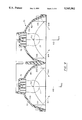
- FIG. 1 is a front view of a reflector of a first embodiment of a dual emitter wide angle warning light in accordance with the present invention
- FIG. 2 is a side elevational view of the warning light of FIG. 1;
- FIG. 3 is an enlarged sectional view, partly in diagrammatic form, of the reflector of FIG. 1 taken along the line 3--3 of FIG. 1;
- FIG. 4 is an enlarged sectional view, partly in diagrammatic form, of the reflector of FIG. 1 taken along the line 4--4 of FIG. 1;
- FIG. 5 is a perspective view, exploded and partly broken away, of the reflector of FIGS. 1-4 and an associated lens;
- FIG. 6 is a view similar to FIG. 1 depicting a reflector assembly of a second embodiment of the present invention
- FIG. 7 is a cross-sectional view of the reflector of FIG. 6 taken in the same direction as FIG. 3;
- FIG. 8 is a view, similar to FIG. 4, of the reflector of FIGS. 6 and 7;
- FIG. 9 is a partial enlarged view, taken in the same direction as FIG. 8, which schematically illustrates the construction of a reflector for a light in accordance with the present invention.
- FIG. 10 is a perspective view of the reflector assembly of FIGS. 6-9 with different types of light emitter installed in the sockets;
- FIG. 11 is representation, related by shading to FIG. 10, of the light pattern produced by the reflector of FIGS. 6-10 when directly viewed and when viewed through a lens having a uniform pattern of optical spreaders.
- FIGS. 1-5 a first embodiment of a two reflector linear array wide angle light in accordance with the present invention is generally indicated by the numeral 70.
- Light 70 comprises a reflector subassembly 72 and a lens 74 which mounts to the reflector.
- Lens 74 may include integral optical spreader ribs 75 or prisms, typically on the surface thereof which faces the reflector, to redirect light received directly from the emitters and light reflected from the reflectors.
- the reflector subassembly 72 comprises two laterally spaced sockets 76 and 78.
- Each socket is capable of receiving a light generator as schematically represented at 77.
- the light generator may be either a halogen lamp as indicated at 77' in FIGS. 5 and 10, or a xenon flash tube, as indicated at 77" in FIG. 10.
- the sockets are designed to support the light generators such that a light emitting portion thereof will lie on the focal point of an associated reflector.
- Each of the sockets 76, 78 has associated therewith a respective concave reflector 80, 82.
- Axis A10 extends through the center of socket 76 and reflector 80, and axis A13 extends through the center of socket 78 and reflector 82.
- the reflectors 80 and 82 are substantially identical and are each defined by three parabolic surfaces. A continuous reflective coating is applied to all of the reflector surfaces and the sockets to provide an optically efficient compound reflector.
- Reflector 80 comprises a central reflective surface S10, which is essentially a segment of a paraboloid of revolution about the central axis A10 through the socket 76.
- a pair of opposing parabolic end surfaces S11 and S12 having substantially the same shape and mirror orientation and also being segments of paraboloids of revolution, are disposed at laterally spaced portions of the parabolic segment surface S10.
- the focal points of the paraboloids of revolution which include surfaces S10, S11, and S12 coincide at a single focal point F10.
- Focal point F10 lies on axis A10 and, as noted above, is intersected by a light emitting portion of light generator 77 mounted in socket 76. As best seen from FIG.
- FIG. 9 which depicts the axis A11 of the paraboloid of revolution which defines surface S11, the axes of the parabolas defined by surfaces S11 and S12 are canted at acute angles ⁇ relative to the axis A10.
- FIG. 9 through the use of broken line showings of different form, also depicts the parabolas defined by reflective surfaces S10 and S11 of reflector 72.
- Reflectors 80 and 82 are substantially identical in shape and dimensions. It should thus be appreciated that reflector 82 likewise comprises a central parabolic dish-like surface S13, which is substantially identical in shape to surface S10, and parabolic end surfaces S14 and S15, which are substantially identical in shape to respective surfaces S11 and S12.
- Surface S13 is a parabolic surface of revolution about axis A13. The axes of the paraboloids of revolution which define surfaces S14 and S15 are canted at an acute angle to the axis A13 and intersect axis A13 at focal point F11.
- Reflectors 80 and 82 cooperate to form a two unit linear array having six co-planar directional axes of high light intensity, i.e., light reflected from each of surfaces S10, S11, S12, S13, S14 and S15 will in the known manner be projected as a beam as indicated respectively by broken lines B10, B11, B12, B13, B14 and B15 in FIG. 4.
- the light beams emanating from the parabolic reflective surfaces will pass through lens 74.
- the lens 74 is provided with internal surface irregularities, spaced optical spreader bars 75 for example, which redirect incident light in a desired direction. Where a wide angle radiation pattern is desired, the light will be redirected by the lens generally about a horizontal plane which is defined by the axes of the paraboloids of revolution. If the light is to be employed as an integral cornering light and warning light, the lens portion in alignment with the reflector which comprises the cornering light will be provided with optics which redirects the directly received and reflected light downwardly and this lens portion will typically be clear. The lens portion which is in registration with the reflector which comprises the warning light will typically be provided with spreader optics and will be colored.
- the distance between focal point F10 and the vertex of surface S10 is 0.687 inches.
- the distance between each of surfaces S11 and S12 and focal point F10 is 1.062 inches.
- the axes of the parabolas defined by end reflector surfaces S11 and S12 are canted at an angle of 35° relative to the central focal axis A10 through surface S10. Analogous relationships are present for surfaces S13, S14 and S15.
- the transverse distance from focal point F10 to the interface between surfaces S10 and S11 is 1.33 inches.
- the lateral transverse dimensional width of the reflector 72 is approximately 7.00 inches.
- each pair of reflectors which form the light 70 comprise co-linear cooperative parabolic sections which define portions of paraboloids of revolution about various directional axes.
- the foregoing arrangements of reflective surfaces results in an enhanced reflection for each of the light generators of a dual emitter light so as to increase the intensity and enhance the directional capabilities of the light.
- the reflector configurations are also achieved within the constraints of a relatively small reflector depth. Reflector depth is an important constraint since the lights may be mounted in the side walls of a vehicle.
- the reflected radiation and light received directly from the light source may be dispersed in a plane by optical spreaders or may be aimed by prisms of a Fresnel lens which are integral with the lens 74 to achieve a desired radiation pattern.
- FIGS. 6-11 a preferred embodiment of a reflector for a light in accordance with the present invention is shown.
- This preferred embodiment differs from the reflector assembly discussed above by the addition, to each of reflectors 80 and 82, of a pair of projections.
- the projections are indicated generally at 90 and 92 and, in the case of reflector 82, the projections are indicated at 94 and 96.
- these four projections are identical with the two projections in each reflector being oppositely disposed as shown. Referencing projection 94 for purposes of explanation, this projection defines two adjoining parabolic reflective surfaces S16 and S18 which are most clearly seen from FIG. 10.
- Projection 94 also has a top surface 102 and a pair of side surfaces 104, 106 which serve simply to connect the surfaces S16 and S18 to the surface S13.
- the paraboloids of revolution defined by reflective surfaces S16 and S18 each have their focal points at the common focal point F11 of surfaces S13, S14 and S15.
- FIG. 9 which shows axis A14 associated with surface S16, the axes of the parabolas defined by surfaces S16 and S18 are canted at an acute angle ⁇ relative to the axes A10 and A11 on which the common focal points F10 and F11 lie.
- the cant angles of axes of the parabolas of surfaces S16 and S18 will typically be the same and will be different from the cant angle of the axes of the surfaces S14 and S15 (or S11 and S12).
- the axis A14 of surface S16 of projection 90 in one reduction to practice where the axes A11 of end reflector surface S11 was canted at an angle of ⁇ of 35° and the axis of reflector S12 was canted at the same angle, was canted at an angle ⁇ of 45° relative to axis A10.
- the surfaces S16 and S18 are also oriented, i.e., the axes of the paraboloids of revolution which include these surfaces are tilted relative to the horizontal plane defined by axes A10 and A13, to achieve the result shown in FIG. 10.
- the light beams represented at B16 and B17 resulting from the focusing action of a pair of adjoining surfaces S16, S18 will be directed away from the horizontal plane.
- the projections 90-96 to the reflectors 80 and 82 enables the "fine tuning" of the radiation pattern from the light assembly.
- the projections and their design particularly the cant angles of the axes of the paraboloids of revolution which are defined by the surfaces of the projections relative to the center axes of the associated reflector and the angle of intersection of these axes with the plane defined by axes A10 and A13, permits the creation of the light pattern represented in FIG. 11.
- FIG. 11 is keyed to FIG. 10 by shading the reflective surfaces in FIG. 10 and representing the light pattern resulting from the reflection off these surfaces with the same shading in FIG. 11.
- FIG. 11A depicts the light pattern produced by one of the reflectors of the two reflector array of FIGS. 6-10 with no lens to redirect the light. It may be seen that the reflective surfaces of the projections produce beams, i.e., enhanced intensity, directed toward the corners of the pattern. In the disclosed embodiment where the cant angles associated with the projections are 45° and the tilt angles are 5°, the "hot" spots were located 5° above and below the horizontal plane as shown. With a 35° cant angle of the end reflectors, the "spots” resulting therefrom were located about the horizontal plane and inwardly toward the center axis with respect to the corner "spots".
- FIG. 11B represents the effect of passing the light pattern of FIG. 11A through the lens 74 of FIG. 5 which has optical spreader optics 75.
- focal points F10 and F11 have been depicted as being on the reflector side of a vertical plane defined by the reflector/lens interface, the focal points could be on the opposite side of this plane.
Abstract
Description
Claims (24)
Priority Applications (1)
| Application Number | Priority Date | Filing Date | Title |
|---|---|---|---|
| US07/452,966 US5045982A (en) | 1989-03-17 | 1989-12-19 | Wide angle warning light |
Applications Claiming Priority (2)
| Application Number | Priority Date | Filing Date | Title |
|---|---|---|---|
| US32489289A | 1989-03-17 | 1989-03-17 | |
| US07/452,966 US5045982A (en) | 1989-03-17 | 1989-12-19 | Wide angle warning light |
Related Parent Applications (1)
| Application Number | Title | Priority Date | Filing Date |
|---|---|---|---|
| US32489289A Continuation-In-Part | 1989-03-17 | 1989-03-17 |
Publications (1)
| Publication Number | Publication Date |
|---|---|
| US5045982A true US5045982A (en) | 1991-09-03 |
Family
ID=26984667
Family Applications (1)
| Application Number | Title | Priority Date | Filing Date |
|---|---|---|---|
| US07/452,966 Expired - Lifetime US5045982A (en) | 1989-03-17 | 1989-12-19 | Wide angle warning light |
Country Status (1)
| Country | Link |
|---|---|
| US (1) | US5045982A (en) |
Cited By (11)
| Publication number | Priority date | Publication date | Assignee | Title |
|---|---|---|---|---|
| US5515255A (en) * | 1994-11-14 | 1996-05-07 | Sterner Lighting Systems Incorporated | Lamp reflector |
| US5622427A (en) * | 1993-09-03 | 1997-04-22 | Simplex Time Recorder Company | Emergency strobe light |
| FR2745364A1 (en) * | 1996-02-23 | 1997-08-29 | Valeo Vision | Automobile indicating especially reversing, light, broad but shallow |
| EP0900977A2 (en) | 1997-08-27 | 1999-03-10 | Wai-Lam Chu | Lighting fixture having fluorescent source |
| US6155694A (en) * | 1998-04-16 | 2000-12-05 | Whelen Engineering Company, Inc. | Composite warning light with emission pattern matching |
| FR2811407A1 (en) * | 2000-07-08 | 2002-01-11 | Hella Kg Hueck & Co | FIRE FOR VEHICLES |
| US6364514B1 (en) * | 1999-11-30 | 2002-04-02 | Koito Manufacturing Co., Ltd. | Vehicular indicator lamp |
| US20040075575A1 (en) * | 1998-11-06 | 2004-04-22 | Demarco Ralph Anthony | Recognition/anti-collision light for aircraft |
| DE102012223584A1 (en) | 2012-12-18 | 2014-06-18 | Automotive Lighting Reutlingen Gmbh | Lamp i.e. signal lamp, for use in motor vehicle, has light source emitting light under pointed angle in reflector, where axes of parabolas and direction of large expansion of reflector define sagittal plane different from meridional plane |
| DE19805217B4 (en) * | 1997-02-21 | 2017-06-29 | Valeo Vision | Motor vehicle headlight with a mirror with laterally juxtaposed zones and method for producing such a mirror |
| DE102009005635B4 (en) * | 2009-01-21 | 2020-01-30 | HELLA GmbH & Co. KGaA | Lighting device for vehicles |
Citations (9)
| Publication number | Priority date | Publication date | Assignee | Title |
|---|---|---|---|---|
| US4208704A (en) * | 1977-06-17 | 1980-06-17 | Lucas Industries Limited | Lamp reflector for a motor vehicle |
| US4386824A (en) * | 1979-12-22 | 1983-06-07 | Lucas Industries Limited | Motor vehicle lamp reflector |
| US4680679A (en) * | 1985-04-22 | 1987-07-14 | Cibie Projecteurs | Motor vehicle main beam headlamp incorporating an elliptical reflector and a parabolic reflector |
| US4722033A (en) * | 1987-04-20 | 1988-01-26 | General Motors Corporation | Vehicle headlamp assembly |
| US4730240A (en) * | 1981-12-09 | 1988-03-08 | U.S. Philips Corporation | Reflector |
| US4740871A (en) * | 1985-11-15 | 1988-04-26 | Cibie Projecteurs | Dual-purpose signal lamp for a vehicle |
| US4754374A (en) * | 1986-05-26 | 1988-06-28 | Cibie Projecteurs | Dipped headlight providing an offset bright spot without using a mask |
| US4825344A (en) * | 1986-02-20 | 1989-04-25 | Stanley Electric Co., Ltd. | Headlamp for vehicles |
| US4954938A (en) * | 1989-02-21 | 1990-09-04 | Whelen Technologies, Inc. | Light with wide angle radiation pattern |
-
1989
- 1989-12-19 US US07/452,966 patent/US5045982A/en not_active Expired - Lifetime
Patent Citations (9)
| Publication number | Priority date | Publication date | Assignee | Title |
|---|---|---|---|---|
| US4208704A (en) * | 1977-06-17 | 1980-06-17 | Lucas Industries Limited | Lamp reflector for a motor vehicle |
| US4386824A (en) * | 1979-12-22 | 1983-06-07 | Lucas Industries Limited | Motor vehicle lamp reflector |
| US4730240A (en) * | 1981-12-09 | 1988-03-08 | U.S. Philips Corporation | Reflector |
| US4680679A (en) * | 1985-04-22 | 1987-07-14 | Cibie Projecteurs | Motor vehicle main beam headlamp incorporating an elliptical reflector and a parabolic reflector |
| US4740871A (en) * | 1985-11-15 | 1988-04-26 | Cibie Projecteurs | Dual-purpose signal lamp for a vehicle |
| US4825344A (en) * | 1986-02-20 | 1989-04-25 | Stanley Electric Co., Ltd. | Headlamp for vehicles |
| US4754374A (en) * | 1986-05-26 | 1988-06-28 | Cibie Projecteurs | Dipped headlight providing an offset bright spot without using a mask |
| US4722033A (en) * | 1987-04-20 | 1988-01-26 | General Motors Corporation | Vehicle headlamp assembly |
| US4954938A (en) * | 1989-02-21 | 1990-09-04 | Whelen Technologies, Inc. | Light with wide angle radiation pattern |
Cited By (16)
| Publication number | Priority date | Publication date | Assignee | Title |
|---|---|---|---|---|
| US5622427A (en) * | 1993-09-03 | 1997-04-22 | Simplex Time Recorder Company | Emergency strobe light |
| US5865527A (en) * | 1993-09-03 | 1999-02-02 | Simplex Time Recorder Co. | Emergency strobe light |
| US5515255A (en) * | 1994-11-14 | 1996-05-07 | Sterner Lighting Systems Incorporated | Lamp reflector |
| FR2745364A1 (en) * | 1996-02-23 | 1997-08-29 | Valeo Vision | Automobile indicating especially reversing, light, broad but shallow |
| DE19805217B4 (en) * | 1997-02-21 | 2017-06-29 | Valeo Vision | Motor vehicle headlight with a mirror with laterally juxtaposed zones and method for producing such a mirror |
| US6357894B1 (en) * | 1997-08-27 | 2002-03-19 | Prescolite, Inc. | Lighting fixture having fluorescent source |
| US5918969A (en) * | 1997-08-27 | 1999-07-06 | Prescolite-Moldcast Lighting Company | Lighting fixture having fluorescent source |
| EP0900977A2 (en) | 1997-08-27 | 1999-03-10 | Wai-Lam Chu | Lighting fixture having fluorescent source |
| US6155694A (en) * | 1998-04-16 | 2000-12-05 | Whelen Engineering Company, Inc. | Composite warning light with emission pattern matching |
| US20040075575A1 (en) * | 1998-11-06 | 2004-04-22 | Demarco Ralph Anthony | Recognition/anti-collision light for aircraft |
| US6989768B2 (en) * | 1998-11-06 | 2006-01-24 | Goodrich Corporation | Recognition/anti-collision light for aircraft |
| US6364514B1 (en) * | 1999-11-30 | 2002-04-02 | Koito Manufacturing Co., Ltd. | Vehicular indicator lamp |
| FR2811407A1 (en) * | 2000-07-08 | 2002-01-11 | Hella Kg Hueck & Co | FIRE FOR VEHICLES |
| DE102009005635B4 (en) * | 2009-01-21 | 2020-01-30 | HELLA GmbH & Co. KGaA | Lighting device for vehicles |
| DE102012223584A1 (en) | 2012-12-18 | 2014-06-18 | Automotive Lighting Reutlingen Gmbh | Lamp i.e. signal lamp, for use in motor vehicle, has light source emitting light under pointed angle in reflector, where axes of parabolas and direction of large expansion of reflector define sagittal plane different from meridional plane |
| DE102012223584B4 (en) | 2012-12-18 | 2018-08-02 | Automotive Lighting Reutlingen Gmbh | Motor vehicle light |
Similar Documents
| Publication | Publication Date | Title |
|---|---|---|
| US4974138A (en) | Lighting device | |
| US8206005B2 (en) | Light assembly | |
| US4453203A (en) | Lighting fixture reflector | |
| US4709312A (en) | Floodlight with improved reflector system | |
| US4293901A (en) | Reflector system having sharp light cutoff characteristics | |
| US6910792B2 (en) | Projection-type vehicular headlamp having improved lateral illumination | |
| US7824067B2 (en) | Emergency light fixture having an efficient reflector assembly | |
| US4701832A (en) | Luminaire for roadway and area lighting | |
| JP4080543B2 (en) | lighting equipment | |
| US5045982A (en) | Wide angle warning light | |
| US6648490B2 (en) | Reflector lighting fixture, especially for in-the-floor, in-the-wall or in-the-ceiling lighting | |
| US5230560A (en) | Anti-collision light assembly | |
| US4954938A (en) | Light with wide angle radiation pattern | |
| US7131749B2 (en) | Heat distributing hybrid reflector lamp or illumination system | |
| US4985814A (en) | Warning light with quadruple reflective surfaces | |
| US5373430A (en) | Wide angle beam pattern lamp | |
| US5040103A (en) | Light assembly for wide area illumination | |
| US5645344A (en) | Luminaire | |
| US5235499A (en) | Lamp system having a torroidal light emitting member | |
| US4866329A (en) | Wide angle warning light | |
| US3786248A (en) | Luminaire | |
| US3654451A (en) | Floodlight | |
| US3257553A (en) | Luminaire | |
| GB2246854A (en) | Lamps and reflectors | |
| JP3124235B2 (en) | Vehicle lighting |
Legal Events
| Date | Code | Title | Description |
|---|---|---|---|
| AS | Assignment |
Owner name: WHELEN TECHNOLOGIES, INC., A CT CORP., CONNECTICUT Free format text: ASSIGNMENT OF ASSIGNORS INTEREST.;ASSIGNOR:LYONS, H. WAYNE;REEL/FRAME:005200/0202 Effective date: 19891218 |
|
| STCF | Information on status: patent grant |
Free format text: PATENTED CASE |
|
| FPAY | Fee payment |
Year of fee payment: 4 |
|
| FEPP | Fee payment procedure |
Free format text: PAT HLDR NO LONGER CLAIMS SMALL ENT STAT AS SMALL BUSINESS (ORIGINAL EVENT CODE: LSM2); ENTITY STATUS OF PATENT OWNER: LARGE ENTITY |
|
| AS | Assignment |
Owner name: WHELEN ENGINEERING COMPANY, INC., CONNECTICUT Free format text: CHANGE OF NAME;ASSIGNOR:WHELEN TECHNOLOGIES, INC.;REEL/FRAME:007833/0831 Effective date: 19941216 |
|
| FEPP | Fee payment procedure |
Free format text: PAYOR NUMBER ASSIGNED (ORIGINAL EVENT CODE: ASPN); ENTITY STATUS OF PATENT OWNER: LARGE ENTITY |
|
| FPAY | Fee payment |
Year of fee payment: 8 |
|
| FPAY | Fee payment |
Year of fee payment: 12 |
|
| REMI | Maintenance fee reminder mailed |