US5047300A - Ultra-thin plate electrochemical cell - Google Patents
Ultra-thin plate electrochemical cell Download PDFInfo
- Publication number
- US5047300A US5047300A US07/366,867 US36686789A US5047300A US 5047300 A US5047300 A US 5047300A US 36686789 A US36686789 A US 36686789A US 5047300 A US5047300 A US 5047300A
- Authority
- US
- United States
- Prior art keywords
- separator
- positive
- negative
- plates
- edge
- Prior art date
- Legal status (The legal status is an assumption and is not a legal conclusion. Google has not performed a legal analysis and makes no representation as to the accuracy of the status listed.)
- Expired - Lifetime
Links
Images


Classifications
-
- H—ELECTRICITY
- H01—ELECTRIC ELEMENTS
- H01M—PROCESSES OR MEANS, e.g. BATTERIES, FOR THE DIRECT CONVERSION OF CHEMICAL ENERGY INTO ELECTRICAL ENERGY
- H01M10/00—Secondary cells; Manufacture thereof
- H01M10/04—Construction or manufacture in general
- H01M10/0404—Machines for assembling batteries
- H01M10/0409—Machines for assembling batteries for cells with wound electrodes
-
- H—ELECTRICITY
- H01—ELECTRIC ELEMENTS
- H01M—PROCESSES OR MEANS, e.g. BATTERIES, FOR THE DIRECT CONVERSION OF CHEMICAL ENERGY INTO ELECTRICAL ENERGY
- H01M10/00—Secondary cells; Manufacture thereof
- H01M10/04—Construction or manufacture in general
- H01M10/0431—Cells with wound or folded electrodes
-
- H—ELECTRICITY
- H01—ELECTRIC ELEMENTS
- H01M—PROCESSES OR MEANS, e.g. BATTERIES, FOR THE DIRECT CONVERSION OF CHEMICAL ENERGY INTO ELECTRICAL ENERGY
- H01M10/00—Secondary cells; Manufacture thereof
- H01M10/06—Lead-acid accumulators
- H01M10/12—Construction or manufacture
- H01M10/125—Cells or batteries with wound or folded electrodes
-
- H—ELECTRICITY
- H01—ELECTRIC ELEMENTS
- H01M—PROCESSES OR MEANS, e.g. BATTERIES, FOR THE DIRECT CONVERSION OF CHEMICAL ENERGY INTO ELECTRICAL ENERGY
- H01M10/00—Secondary cells; Manufacture thereof
- H01M10/24—Alkaline accumulators
- H01M10/28—Construction or manufacture
- H01M10/286—Cells or batteries with wound or folded electrodes
-
- H—ELECTRICITY
- H01—ELECTRIC ELEMENTS
- H01M—PROCESSES OR MEANS, e.g. BATTERIES, FOR THE DIRECT CONVERSION OF CHEMICAL ENERGY INTO ELECTRICAL ENERGY
- H01M4/00—Electrodes
- H01M4/02—Electrodes composed of, or comprising, active material
-
- H—ELECTRICITY
- H01—ELECTRIC ELEMENTS
- H01M—PROCESSES OR MEANS, e.g. BATTERIES, FOR THE DIRECT CONVERSION OF CHEMICAL ENERGY INTO ELECTRICAL ENERGY
- H01M50/00—Constructional details or processes of manufacture of the non-active parts of electrochemical cells other than fuel cells, e.g. hybrid cells
- H01M50/50—Current conducting connections for cells or batteries
- H01M50/531—Electrode connections inside a battery casing
- H01M50/533—Electrode connections inside a battery casing characterised by the shape of the leads or tabs
-
- H—ELECTRICITY
- H01—ELECTRIC ELEMENTS
- H01M—PROCESSES OR MEANS, e.g. BATTERIES, FOR THE DIRECT CONVERSION OF CHEMICAL ENERGY INTO ELECTRICAL ENERGY
- H01M50/00—Constructional details or processes of manufacture of the non-active parts of electrochemical cells other than fuel cells, e.g. hybrid cells
- H01M50/50—Current conducting connections for cells or batteries
- H01M50/531—Electrode connections inside a battery casing
- H01M50/536—Electrode connections inside a battery casing characterised by the method of fixing the leads to the electrodes, e.g. by welding
-
- H—ELECTRICITY
- H01—ELECTRIC ELEMENTS
- H01M—PROCESSES OR MEANS, e.g. BATTERIES, FOR THE DIRECT CONVERSION OF CHEMICAL ENERGY INTO ELECTRICAL ENERGY
- H01M50/00—Constructional details or processes of manufacture of the non-active parts of electrochemical cells other than fuel cells, e.g. hybrid cells
- H01M50/50—Current conducting connections for cells or batteries
- H01M50/531—Electrode connections inside a battery casing
- H01M50/538—Connection of several leads or tabs of wound or folded electrode stacks
-
- H—ELECTRICITY
- H01—ELECTRIC ELEMENTS
- H01M—PROCESSES OR MEANS, e.g. BATTERIES, FOR THE DIRECT CONVERSION OF CHEMICAL ENERGY INTO ELECTRICAL ENERGY
- H01M50/00—Constructional details or processes of manufacture of the non-active parts of electrochemical cells other than fuel cells, e.g. hybrid cells
- H01M50/50—Current conducting connections for cells or batteries
- H01M50/531—Electrode connections inside a battery casing
- H01M50/54—Connection of several leads or tabs of plate-like electrode stacks, e.g. electrode pole straps or bridges
- H01M50/541—Connection of several leads or tabs of plate-like electrode stacks, e.g. electrode pole straps or bridges for lead-acid accumulators
-
- H—ELECTRICITY
- H01—ELECTRIC ELEMENTS
- H01M—PROCESSES OR MEANS, e.g. BATTERIES, FOR THE DIRECT CONVERSION OF CHEMICAL ENERGY INTO ELECTRICAL ENERGY
- H01M10/00—Secondary cells; Manufacture thereof
- H01M10/06—Lead-acid accumulators
-
- H—ELECTRICITY
- H01—ELECTRIC ELEMENTS
- H01M—PROCESSES OR MEANS, e.g. BATTERIES, FOR THE DIRECT CONVERSION OF CHEMICAL ENERGY INTO ELECTRICAL ENERGY
- H01M10/00—Secondary cells; Manufacture thereof
- H01M10/24—Alkaline accumulators
- H01M10/30—Nickel accumulators
-
- H—ELECTRICITY
- H01—ELECTRIC ELEMENTS
- H01M—PROCESSES OR MEANS, e.g. BATTERIES, FOR THE DIRECT CONVERSION OF CHEMICAL ENERGY INTO ELECTRICAL ENERGY
- H01M4/00—Electrodes
- H01M4/02—Electrodes composed of, or comprising, active material
- H01M4/64—Carriers or collectors
- H01M4/66—Selection of materials
- H01M4/68—Selection of materials for use in lead-acid accumulators
-
- H—ELECTRICITY
- H01—ELECTRIC ELEMENTS
- H01M—PROCESSES OR MEANS, e.g. BATTERIES, FOR THE DIRECT CONVERSION OF CHEMICAL ENERGY INTO ELECTRICAL ENERGY
- H01M50/00—Constructional details or processes of manufacture of the non-active parts of electrochemical cells other than fuel cells, e.g. hybrid cells
- H01M50/50—Current conducting connections for cells or batteries
- H01M50/543—Terminals
- H01M50/552—Terminals characterised by their shape
- H01M50/559—Terminals adapted for cells having curved cross-section, e.g. round, elliptic or button cells
-
- H—ELECTRICITY
- H01—ELECTRIC ELEMENTS
- H01M—PROCESSES OR MEANS, e.g. BATTERIES, FOR THE DIRECT CONVERSION OF CHEMICAL ENERGY INTO ELECTRICAL ENERGY
- H01M50/00—Constructional details or processes of manufacture of the non-active parts of electrochemical cells other than fuel cells, e.g. hybrid cells
- H01M50/50—Current conducting connections for cells or batteries
- H01M50/572—Means for preventing undesired use or discharge
- H01M50/584—Means for preventing undesired use or discharge for preventing incorrect connections inside or outside the batteries
- H01M50/59—Means for preventing undesired use or discharge for preventing incorrect connections inside or outside the batteries characterised by the protection means
- H01M50/593—Spacers; Insulating plates
-
- H—ELECTRICITY
- H01—ELECTRIC ELEMENTS
- H01M—PROCESSES OR MEANS, e.g. BATTERIES, FOR THE DIRECT CONVERSION OF CHEMICAL ENERGY INTO ELECTRICAL ENERGY
- H01M6/00—Primary cells; Manufacture thereof
- H01M6/04—Cells with aqueous electrolyte
- H01M6/06—Dry cells, i.e. cells wherein the electrolyte is rendered non-fluid
- H01M6/10—Dry cells, i.e. cells wherein the electrolyte is rendered non-fluid with wound or folded electrodes
-
- Y—GENERAL TAGGING OF NEW TECHNOLOGICAL DEVELOPMENTS; GENERAL TAGGING OF CROSS-SECTIONAL TECHNOLOGIES SPANNING OVER SEVERAL SECTIONS OF THE IPC; TECHNICAL SUBJECTS COVERED BY FORMER USPC CROSS-REFERENCE ART COLLECTIONS [XRACs] AND DIGESTS
- Y02—TECHNOLOGIES OR APPLICATIONS FOR MITIGATION OR ADAPTATION AGAINST CLIMATE CHANGE
- Y02E—REDUCTION OF GREENHOUSE GAS [GHG] EMISSIONS, RELATED TO ENERGY GENERATION, TRANSMISSION OR DISTRIBUTION
- Y02E60/00—Enabling technologies; Technologies with a potential or indirect contribution to GHG emissions mitigation
- Y02E60/10—Energy storage using batteries
-
- Y—GENERAL TAGGING OF NEW TECHNOLOGICAL DEVELOPMENTS; GENERAL TAGGING OF CROSS-SECTIONAL TECHNOLOGIES SPANNING OVER SEVERAL SECTIONS OF THE IPC; TECHNICAL SUBJECTS COVERED BY FORMER USPC CROSS-REFERENCE ART COLLECTIONS [XRACs] AND DIGESTS
- Y02—TECHNOLOGIES OR APPLICATIONS FOR MITIGATION OR ADAPTATION AGAINST CLIMATE CHANGE
- Y02P—CLIMATE CHANGE MITIGATION TECHNOLOGIES IN THE PRODUCTION OR PROCESSING OF GOODS
- Y02P70/00—Climate change mitigation technologies in the production process for final industrial or consumer products
- Y02P70/50—Manufacturing or production processes characterised by the final manufactured product
Definitions
- This invention relates to the method for manufacture of electrochemical cells having superior recharge and discharge capabilities.
- electrochemical cells are comprised of ultra-thin spirally wound plates contained within a hermetically sealed container.
- the breakthrough invention in lead acid cells is described in U.S. Pat. No. 3,862,861 of McClelland et al.
- the McClelland patent discloses the incorporation of several elements that combine to alleviate each of these problems associated with the traditional lead acid cell.
- the McClelland invention recognized the potential of utilizing the electrochemical recombination reaction between the oxygen and hydrogen formed during overcharging to maintain a balanced system.
- a lead acid cell could be produced such that the electrolyte could be maintained in a "starved" condition. Rather than having an excess of electrolyte, the cell could be operated with a minimal amount of electrolyte present in the system. In order to maintain a starved condition, it is necessary to have sufficient absorbant material or pores within the cell to contain the electrolyte.
- McClelland was able to accomplish two distinct functions.
- the absorptive separator allowed the flow of gases and electrolyte between the positive and negative plates, thereby allowing the oxygen cycle to function.
- the absorptive separator also acts as a wick to hold the electrolyte within the cell without the necessity of having free electrolyte in the system.
- McClelland also discloses a configuration of the plates and separator so that the elements are held tightly together. Fluid flow of the lead is thus prohibited. It was then possible to use considerably purer lead grids that are electrochemically more efficient than the calcium containing lead plates previously used. Venting means are included in the McClelland device as a safety release device in case, through some malfunction, gases generated during recharging were not reconverted to water. However, since there is little or no non-absorbed electrolyte in the cell, there is almost no danger of acid leaking from the cell.
- the Nelson patent discloses the use of both thin lead grids and thin layers of reactive paste.
- a basic shortcoming in the Nelson device is that the paste residing within the grid openings can have a greatly increased distance to the lead plate material.
- the openings in the lead plate grid are constructed so that the distance from the center of the grid to the grid strands is significantly greater than the thickness of the paste layer on the face of the plate. Since the performance characteristics of electrochemical cells is proportional to the thickness of the lead plates and the thickness of the paste layer, the use of grids greatly decreases the efficiency of the cells.
- spirally rolled electrochemical cells are designed so that tabs are periodically incorporated into the plates--the tabs of one polarity going one way, the tabs of the opposite polarity going the other--in order to make connections from the plates to the cell terminals.
- This arrangement creates a problem in high rate discharge cells. The rapid discharge of substantial amounts of power generates a significant amount of heat along the tabs and terminals due to the relatively high resistance of the arrangement.
- U.S. Pat. No. 4,322,484 of Sugalski describes the use of an additional element within the cell to act as a heat sink.
- the electrochemical cell of the present invention is characterized by the use of ultra-thin non-perforated electrode plates along with ultra-thin active material layers and thin absorptive separator material layers.
- the cell is initially produced with an excess volume of electrolyte, but through processing, a volume of electrolyte is achieved in the cell, and the electrolyte volume is maintained in an almost saturated condition with respect to the absorptive capacity of the separator and the electrode materials.
- electrochemical cells are produced utilizing non-perforated sheets of lead or nickel approximately 0.002 inches thick.
- the active material or paste maintained on the surface of both sides of the sheet are approximately 0.002 to 0.003 inches thick.
- the inter plate spacing is 0.005 to 0.007 inches.
- the cell of the present invention is further characterized by an exceptionally high plate surface area to active material ratio.
- the active material When using lead acid cells, the active material may be sulfated lead pastes or PbO and Pb 3 O 4 for the positive and PbO for the negative plates.
- the specific gravity of the electrolyte is about 1.28.
- the lead plates are greater than 99% pure. If containing tin, the lead may be 99.50% pure lead and 50% tin. If tin is not used, the lead is approximately 99.99% pure.
- separator materials Any number of separator materials known in the art may be utilized with the present invention.
- One suitable glass microfiber material consists of 90% of fibers of 1 to 4 microns in diameter and 10% of fibers being larger fibers existing as a woven or oriented mat. Examples of acceptable separator materials are described in U.S. Pat. Nos. 4,233,379 of Gross et al. and 4,465,748 of Harris.
- the surface of the electrode plates is either physically roughened or chemically etched to increase the adhesion of the thin layer of active material to the plate surface.
- the electrochemical cell of the present invention is further characterized by an improved terminal electrode attachment assembly. According to the invention, one continuous edge of the electrode plate is in contact with the cell terminal, resulting in an efficient low resistance conductive pathway that reduces the build-up of excess heat in a rapid discharge cell.
- the electrochemical cell of the present invention demonstrates dramatic improvements in recharge/discharge capabilities over cells produced as described in the various references cited above. Maximum current capability is increased and the current value remains at near its maximum throughout a longer period of its discharge profile. Recharge times are also reduced dramatically. Recharge can be accomplished at up to 10C (or ten times the amperage of the cell), as long as the cell is not overcharged.
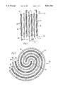
- FIG. 1 is a diagrammatic vertical cross-sectional view of a pair of cell units according to one embodiment of the present invention.
- FIG. 2 is a diagrammatic horizontal cross-sectional view of a spirally wound cell unit according to one embodiment of the present invention.
- FIG. 3 is a plan view of an embodiment of a terminal connector according to the present invention.
- FIG. 4 is a plan view an alternative embodiment of a terminal connector according to the present invention.
- FIG. 5 is a diagrammatic vertical cross-sectional view of a portion of a spirally wound cell unit according to one embodiment of the present invention.
- FIG. 6 is a partial cross-sectional view of the terminal portion of an embodiment of the cell unit of the present invention.
- FIG. 7 depicts discharge curves comparing cells of this invention with conventional cells.
- an electrochemical cell having both excellent charge and discharge characteristics is described. Technological breakthroughs in the fields of thin film handling have made it possible to create high rate electrochemical cells that have performance characteristics that are unprecedented in the field.
- the electrochemical cell of the present invention is composed of ultra-thin non-perforated films of an electrochemically active metal--generally lead or nickel --that is coated on each side with an electrochemically active paste.
- the positive and negative "plates" of the electrochemical cell are maintained apart from each other by separator material.
- the separator material also acts to absorb the electrolyte that is contained with the enclosed cell system.
- FIG. 1 A diagrammatic view of a cell unit according to the present invention is seen in FIG. 1.
- Positive plate 10, separator 12 and negative plate 14 constitute an electrochemical unit cell 16.
- Both the positive plate 10 and the negative plate 14 consist of an ultra-thin film 18 of either lead or nickel partially coated on both major faces with a layer of a suitable electrochemically active paste 20.
- the film not only be extremely thin, but that it not be perforated.
- One of the more critical elements of the present invention is that there not be any active material paste 20 at a distance of greater than 0.005 inches from the film 18 on which it is coated.
- the films 18 utilized in the electrochemical cell are no greater than 0.005 inches thick. In the preferred embodiments, the films 18 are about 0.003 to 0.0015 inches thick. Handling such thin films and incorporating the same into functional electrochemical cells was previously thought to be impossible. In certain ways, the electrochemical cells of the present invention are constructed along the lines of standard electrolytic capacitors.
- a thin layer of the active material paste 20 is applied to a large portion of both major faces of the negative and positive films 18.
- Each layer is, at the most, 0.005 inches thick, and in the preferred embodiments of the invention, the layers of active material paste 20 are about 0.002 to 0.003 inches thick.
- Both positive and negative plates 10, 14 are, at the most, 0.010 inches thick and in the preferred embodiment have a thickness of about 0.005 to 0.008 inches, with an interplate spacing of about 0.005 to 0.007 inches.
- the positive plate 10 In each unit cell 16, the positive plate 10, the separator 12 and the negative plate 14 are held against each in a specific physical relation as seen in FIG. 1. Both major faces of the metal films 18 are coated with active material paste 20, except along alternating horizontal edges 22, 24. On the positive plate 10, the portions of the major faces 26 adjacent to the upper horizontal edge 22 are not coated with the active material paste 20, and on negative plate 14, the portions of the major faces 28 adjacent to the lower horizontal edge 24 are not coated with the active material paste 20.
- plate 10, 14 and separator 12 The physical arrangement of plate 10, 14 and separator 12 is also shown in FIG. 1.
- the positive plate 10 is positioned so that the uncoated portion and the 6 extends above both the negative plate. separator 12.
- the separator 12 extends beyond the negative plate 14 but not as far as the positive plate 0 and to the bottom, the separator 12 extends beyond the positive plate 10 but not as far as the negative plate 14. It could, of course, be constructed so that the relative position of the positive and negative plates be reversed.
- the negative and positive film 18 is about 1.5 inches high.
- the uncoated ends extend about 6-8 mm beyond the coated plate, and the separator 12 extends about 2-4 mm beyond the coated plate.
- the surfaces of the film 18 that are to be coated are preferably etched or roughened prior to application of the active paste 20. This allows for a more adequate adhesion between the paste and the film.
- the electrochemical cell is constructed of a single spirally wound unit cell as is shown in FIG. 2.
- the invention could also be employed utilizing parallel stacks of any number of unit cells.
- a single continuous sheet of separator 12 may be employed to separate the negative 14 and positive 10 plates from each other as seen in FIG. 2.
- the preferred terminal connector 32 of the present invention is seen in FIG. 3.
- the terminal connector 32 is a component of the completed electrochemical cell formed near both the top (as seen in FIGS. 1 and 5, the positive terminal) and the bottom (as seen in FIGS. 1 and 5, the negative terminal) of the spirally wound plate and separator unit.
- the preferred terminal connector 32 is a conically shaped conductive element that is about the same diameter as the spirally wound cell, and that has a plurality of oblong shaped apertures 34 radiating outwardly from the center portion of the circle.
- the connector 32 may have a connector post 33 for ease in connection.
- An alternative connector 80 is seen in FIG. 4. This daisy-shaped connector has a plurality of radiating wings 82 protruding out from the body 84 of the connector 80.
- FIG. 5 A unit cell having the physical relationships as shown in FIGS. 1 and 2 and having terminal connectors 32 in place, is seen in FIG. 5.
- the connectors 32 are applied to the top and bottom of the cell (where the uncoated portions 26 and 28 of the negative and positive plates are extending out coplanarly) in a spiral configuration. The effect of such a motion requires that the uncoated portions 26 and 28 are bent radially inwardly. Due to the respective positions of the positive and negative plates 10, 14 and the separator 12, the uncoated portions 26, 28 contact each other and are separated from the opposite polarity plate by the separator 12. It can be seen, therefore, that the relative physical positions of the plates and separator is critical in obtaining a proper connection between the terminal connector 32 and the uncoated portions 26, 28 of the plates.
- the terminal arrangement of the present invention provides an improved means for maximizing contact between the respective plates 10, 14 and the terminal connector 32.
- the connectors 32 are permanently attached to the ends of the electrochemical cell by laser welding or plasma arc welding.
- the oblong apertures 34 are spaced to allow access to the interior surface of the connector 32 for welding.
- FIG. 6 An embodiment of the completed electrochemical cell terminal assembly 40 is seen in FIG. 6.
- the spirally wound unit cell 16 is held first in a polypropylene sealed container 42 and second in a stainless steel container 43 that is preferably equipped with vent means (not shown).
- the terminal connectors 32 are held in place by a torroidal brace 45, that holds such connectors 32 in contact with the exterior terminal 44.
- Insulation washer 51 insulates the external terminal 44 from the stainless steel container 43.
- the lead non-perforated film 18 is preferably composed of lead that is at least 99.99% pure.
- the lead may be 99.50% pure and contain about 0.50% tin.
- the lead film for each embodiment 18 is about 0.005 inches or less thick, and is preferably about 0.003 to 0015 inches thick.
- active material pastes 20 For lead acid electrochemical cells, there are a number of widely known combinations of active material pastes 20 that are typically used. Any of these commonly utilized systems would be appropriate for use with this invention. For example, sulfated PbO pastes used on both the positive and negative plates provides a satisfactory system, as does the use of PbO and Pb 3 O 4 on the positive plate and PbO on the negative plate. The use of sponge lead, litharge, red lead or leady oxide is also possible. The only important factor is that the active material paste 20 be of a nature so that it can be applied to the ultra-thin lead film 18 in a consistently thin layer, as described above.
- the separator is a glass micro-fiber wherein 90% of the fibers are 1-4 microns in diameter, and 10% of the fibers are longer (up to 1 inch in length), being about 95% porous in the uncompressed state.
- the specific gravity of the sulfuric acid electrolyte solution used is between 1.20 and 1.32.
- Electrolyte concentration in the cell is established by adding an excess of electrolyte, and heating the cell in order to vent excess electrolyte.
- the type of vent used on the electrochemical cell may be similar to those described in the literature and known by those with ordinary skill in the art, and operates to vent excess gases when the internal pressure exceeds a certain level.
- the electrolyte remaining in the cell after heating and venting will be in an almost saturated state and some internal pressure (above atmospheric) will be maintained when in its normal operational state.
- the cell of the present invention In its operable state, the cell of the present invention is maintained so that the total void volume of the compressed separator and the active material is substantially filled, yet there is no free electrolyte present.
- the exact amount of electrolyte present in the cell, within these limits, is not critical to the functioning of the present invention.
- FIG. 7 shows the discharge curve for a lead acid electrochemical cell according to the embodiment of the present invention (C) in comparison with discharge curves for the cells described in U.S. Pat. Nos. 3,862,861 of McClelland et al. (A) and 4,769,299 of Nelson (B).
- C lead acid electrochemical cell according to the embodiment of the present invention
- the electrochemical cell used to create the discharge curve seen in FIG. 7 has the following characteristics:
- the non-perforated lead film was composed of 99.50% lead and 0.50% tin; the lead films were 0.002 inches thick and were coated with a layer of 0.002 inches thick of sulfated pastes --the total plate thickness being 0.006 inches; the electrolyte was sulfuric acid with a specific gravity of 1.28; the glass micro-fiber separator was 95% porous in its uncompressed state and contained 90% 1-4 micron diameter fibers and 10% larger fibers up to 1 inch in length and has a surface area of about 2m 2 /g.
- the lead films would be 45 inches long and 1.5 inches high, and there would be about 260 cm 2 of surface area for each gram of active material paste.
- the cells of the present invention can be recharged at extremely high rates relative to cells currently available. As long as significant overcharging is now allowed, the cells can be recharged at up to 10C, or ten times the rate amperage of the cell.
- the present invention has the applications in all electrochemical cells, and in particular, the lead acid and nickel cadmium systems.
- the descriptions given and the example presented are for the purposes of illustration and are not meant to limit the claims of the application as set forth below.
Abstract
Description
Claims (4)
Priority Applications (14)
| Application Number | Priority Date | Filing Date | Title |
|---|---|---|---|
| US07/366,867 US5047300A (en) | 1989-06-14 | 1989-06-14 | Ultra-thin plate electrochemical cell |
| US07/413,272 US5045086A (en) | 1989-06-14 | 1989-09-27 | Method for manufacture of electrochemical cell |
| EP90911144A EP0494147B1 (en) | 1989-06-14 | 1990-06-14 | Ultra-thin plate electrochemical cell |
| EP99116070A EP0961335B1 (en) | 1989-06-14 | 1990-06-14 | Method of manufacture of an ultra-thin plate electrochemical cell |
| AT99116070T ATE393968T1 (en) | 1989-06-14 | 1990-06-14 | METHOD FOR PRODUCING AN ELECTROCHEMICAL CELL USING ULTRA-THIN PLATES |
| EP99116071A EP0961336B1 (en) | 1989-06-14 | 1990-06-14 | Ultra-thin plate electromechanical cell |
| AT99116071T ATE422717T1 (en) | 1989-06-14 | 1990-06-14 | ELECTROCHEMICAL CELL MADE OF ULTRA-THIN FILM |
| DE69034252T DE69034252D1 (en) | 1989-06-14 | 1990-06-14 | Method for producing an electrochemical cell with ultrathin plates |
| DE69033485T DE69033485T2 (en) | 1989-06-14 | 1990-06-14 | ELECTROCHEMICAL CELL CONSISTING OF ULTRA-THIN FILMS |
| ES90911144T ES2146198T3 (en) | 1989-06-14 | 1990-06-14 | ELECTROCHEMICAL BATTERY WITH ULTRA-THIN PLATE. |
| DE69034262T DE69034262D1 (en) | 1989-06-14 | 1990-06-14 | Electrochemical cell made from ultrathin films |
| AT90911144T ATE190758T1 (en) | 1989-06-14 | 1990-06-14 | ELECTROCHEMICAL CELL CONSISTING OF ULTRA-THIN FILM |
| US07/757,447 US5198313A (en) | 1989-06-14 | 1991-09-10 | Battery end connector |
| US08/074,933 US5368961A (en) | 1989-06-14 | 1993-06-10 | Thin plate electrochemical cell |
Applications Claiming Priority (1)
| Application Number | Priority Date | Filing Date | Title |
|---|---|---|---|
| US07/366,867 US5047300A (en) | 1989-06-14 | 1989-06-14 | Ultra-thin plate electrochemical cell |
Related Child Applications (2)
| Application Number | Title | Priority Date | Filing Date |
|---|---|---|---|
| US07/413,272 Continuation-In-Part US5045086A (en) | 1989-06-14 | 1989-09-27 | Method for manufacture of electrochemical cell |
| US07/757,447 Continuation-In-Part US5198313A (en) | 1989-06-14 | 1991-09-10 | Battery end connector |
Publications (1)
| Publication Number | Publication Date |
|---|---|
| US5047300A true US5047300A (en) | 1991-09-10 |
Family
ID=23444904
Family Applications (1)
| Application Number | Title | Priority Date | Filing Date |
|---|---|---|---|
| US07/366,867 Expired - Lifetime US5047300A (en) | 1989-06-14 | 1989-06-14 | Ultra-thin plate electrochemical cell |
Country Status (1)
| Country | Link |
|---|---|
| US (1) | US5047300A (en) |
Cited By (42)
| Publication number | Priority date | Publication date | Assignee | Title |
|---|---|---|---|---|
| US5336273A (en) * | 1992-11-27 | 1994-08-09 | Gould Electronics Inc. | Laser sealed solid electrolyte cell housed within a ceramic frame and the method for producing it |
| US5354629A (en) * | 1991-10-09 | 1994-10-11 | Sanyo Electric Co., Ltd. | Monaqueous electrolyte battery |
| US5368961A (en) * | 1989-06-14 | 1994-11-29 | Bolder Battery, Inc. | Thin plate electrochemical cell |
| US5370711A (en) * | 1993-07-21 | 1994-12-06 | Ev Energy Systems, Inc. | Method for making an electrical energy storage device |
| WO1994029909A1 (en) * | 1993-06-14 | 1994-12-22 | Bolder Battery, Inc. | Method and apparatus for assembling electrochemical cell |
| US5554460A (en) * | 1994-07-05 | 1996-09-10 | Motorola, Inc. | Multi-layered coated membrane electrodes for electrochemical cells and cells using same |
| WO1997012407A1 (en) * | 1995-09-27 | 1997-04-03 | Bolder Technologies Corp. | Method and apparatus for assembling electrochemical cell using elastomeric sleeve |
| WO1997048165A1 (en) * | 1996-06-14 | 1997-12-18 | Philips Electronics N.V. | Accumulator device for an electrical and/or electronic apparatus and telecommunication terminal comprising such a device |
| US5709965A (en) * | 1994-04-13 | 1998-01-20 | Saft | Electrical interconnection system for electrochemical generators and batteries |
| FR2752092A1 (en) * | 1996-07-30 | 1998-02-06 | Accumulateurs Fixes | Electrochemical generator with spiral electrodes |
| US5958621A (en) * | 1995-05-19 | 1999-09-28 | Johnson Controls Technology Company | Two-step pasting of thin electrodes |
| US5993983A (en) * | 1997-03-14 | 1999-11-30 | Century Mfg. Co. | Portable power supply using hybrid battery technology |
| US6004689A (en) * | 1995-09-27 | 1999-12-21 | Bolder Technologies Corporation | Battery case |
| US6020086A (en) * | 1996-04-11 | 2000-02-01 | U.S. Philips Corporation | Accumulator device for an electric and/or electronic apparatus having a curved shape |
| US6051336A (en) * | 1998-01-19 | 2000-04-18 | Johnson Controls Technology | Battery case for thin metal film cells |
| EP1008195A1 (en) * | 1997-01-15 | 2000-06-14 | GP Batteries International Limited | Battery case |
| WO2000046868A1 (en) * | 1999-02-04 | 2000-08-10 | Bolder Technologies Corporation | Lead-tin alloy current collectors, batteries made thereof and methods for manufacturing same |
| WO2000062356A1 (en) | 1999-04-08 | 2000-10-19 | Matsushita Electric Industrial Co., Ltd. | Secondary battery |
| US6146785A (en) * | 1997-10-16 | 2000-11-14 | Alcatel | Sealed cell having a multilayer case |
| US6221524B1 (en) | 1998-01-19 | 2001-04-24 | Johnson Controls Technology Company | Strap for thin metal film battery |
| US6255014B1 (en) | 1998-01-19 | 2001-07-03 | Johnson Controls Technology Company | Center point vent cover for battery |
| US6316148B1 (en) | 2000-08-31 | 2001-11-13 | Condord Battery Corporation | Foil-encapsulated, lightweight, high energy electrodes for lead-acid batteries |
| US6534212B1 (en) | 2000-05-05 | 2003-03-18 | Hawker Energy Products, Inc. | High performance battery and current collector therefor |
| US6566010B1 (en) | 2000-11-16 | 2003-05-20 | Concorde Battery Corporation | High energy, lightweight, lead-acid storage battery |
| US6586136B1 (en) | 2000-11-16 | 2003-07-01 | Concorde Battery Corporation | Lightweight, low resistance electrode plate for lead-acid batteries |
| EP1087451A3 (en) * | 1999-09-21 | 2003-07-23 | Matsushita Electric Industrial Co., Ltd. | Electrode plate unit for rechargeable battery and manufacturing method thereof |
| US20030148176A1 (en) * | 2000-03-09 | 2003-08-07 | Gootzen Jozef Franciscus Elisabeth | Battery comprising a plurality of series-connected galvanic cells |
| US6645675B1 (en) | 1999-09-02 | 2003-11-11 | Lithium Power Technologies, Inc. | Solid polymer electrolytes |
| US6664006B1 (en) | 1999-09-02 | 2003-12-16 | Lithium Power Technologies, Inc. | All-solid-state electrochemical device and method of manufacturing |
| US20040083601A1 (en) * | 1999-12-14 | 2004-05-06 | Matsushita Electric Industrial Co., Ltd. | Battery manufacturing method and apparatus |
| US6762926B1 (en) * | 2003-03-24 | 2004-07-13 | Luxon Energy Devices Corporation | Supercapacitor with high energy density |
| US20050207969A1 (en) * | 2004-03-19 | 2005-09-22 | Ges Technologies, S. De R.L. De C.V. | Production of tetrabasic lead sulfate from solid state reactions for the preparation of active plates to be used in lead-acid batteries |
| US20050227368A1 (en) * | 2003-05-20 | 2005-10-13 | Eric Ezan | Method for the detection of fluoride or hydrogen fluoride and detection kit |
| EP1601034A2 (en) * | 2004-05-28 | 2005-11-30 | M&G Eco Battery Institute Co. Ltd. | Secondary battery |
| US20060034415A1 (en) * | 2003-11-21 | 2006-02-16 | Tsang Francis Y | Nuclear voltaic cell |
| US20060039852A1 (en) * | 2004-08-19 | 2006-02-23 | Johnson Controls Technology Company | Method for making lead oxide for lead-acid batteries |
| US20080233474A1 (en) * | 2007-03-19 | 2008-09-25 | Sukjung Son | Rechargeable battery and its fabrication method |
| WO2009019568A2 (en) * | 2007-08-09 | 2009-02-12 | Sung On Andrew Ng | Battery arrangement and electrical system for automotive engine operation |
| FR2927727A1 (en) * | 2008-02-19 | 2009-08-21 | Batscap Sa | MULTIBOBIN ELECTRIC ENERGY STORAGE ASSEMBLY. |
| US20100304197A1 (en) * | 2009-06-02 | 2010-12-02 | Bhardwaj Ramesh C | Flexible foil prismatic battery having improved volumetric efficiency |
| US20100321864A1 (en) * | 2008-02-19 | 2010-12-23 | Philippe Azais | Multiple-track supercapacitor |
| US9537143B2 (en) | 2010-11-10 | 2017-01-03 | Epic Ventures Inc. | Lead acid cell with active materials held in a lattice |
Citations (16)
| Publication number | Priority date | Publication date | Assignee | Title |
|---|---|---|---|---|
| US3395043A (en) * | 1967-05-09 | 1968-07-30 | Shoeld Mark | Storage battery having spiral electrodes of the pasted type |
| US3494800A (en) * | 1968-04-08 | 1970-02-10 | Mark Shoeld | Method of making lead acid storage battery |
| US3650842A (en) * | 1966-04-01 | 1972-03-21 | Accumulateurs Fixes | Electrolytic, secondary and primary cells |
| US3862861A (en) * | 1970-08-03 | 1975-01-28 | Gates Rubber Co | Maintenance-free type lead acid |
| US4137377A (en) * | 1977-10-19 | 1979-01-30 | The Gates Rubber Company | Maintenance-free lead-acid cell |
| US4216280A (en) * | 1977-09-19 | 1980-08-05 | Yuasa Battery Company Limited | Glass fiber separator for storage batteries |
| US4233379A (en) * | 1979-05-17 | 1980-11-11 | Johns-Manville Corporation | Separator for starved electrolyte lead/acid battery |
| US4322284A (en) * | 1980-02-05 | 1982-03-30 | Gulf Research & Development Company | Solvent refining of coal using octahydrophenanthrene-enriched solvent and coal minerals recycle |
| US4332867A (en) * | 1979-11-07 | 1982-06-01 | Matsushita Electric Industrial Co., Ltd. | Battery coil construction |
| US4414295A (en) * | 1982-05-06 | 1983-11-08 | Gates Energy Products, Inc. | Battery separator |
| US4460666A (en) * | 1981-11-24 | 1984-07-17 | Dinkler Leonard R | Coated substrate, preparation thereof, and use thereof |
| US4465748A (en) * | 1982-04-20 | 1984-08-14 | Evans Adlard & Company Limited | Glass fibre paper separator for electrochemical cells |
| US4637966A (en) * | 1983-10-21 | 1987-01-20 | Gates Energy Products, Inc. | Sealed lead-acid cell |
| US4648177A (en) * | 1983-10-21 | 1987-03-10 | Gates Energy Products, Inc. | Method for producing a sealed lead-acid cell |
| US4725516A (en) * | 1983-10-24 | 1988-02-16 | Yuasa Battery Company Limited | Sealed lead-acid battery |
| US4769299A (en) * | 1986-06-27 | 1988-09-06 | Gates Energy Products, Inc. | High rate sealed lead-acid battery with ultrathin plates |
-
1989
- 1989-06-14 US US07/366,867 patent/US5047300A/en not_active Expired - Lifetime
Patent Citations (17)
| Publication number | Priority date | Publication date | Assignee | Title |
|---|---|---|---|---|
| US3650842A (en) * | 1966-04-01 | 1972-03-21 | Accumulateurs Fixes | Electrolytic, secondary and primary cells |
| US3395043A (en) * | 1967-05-09 | 1968-07-30 | Shoeld Mark | Storage battery having spiral electrodes of the pasted type |
| US3494800A (en) * | 1968-04-08 | 1970-02-10 | Mark Shoeld | Method of making lead acid storage battery |
| US3862861A (en) * | 1970-08-03 | 1975-01-28 | Gates Rubber Co | Maintenance-free type lead acid |
| US3862861B1 (en) * | 1970-08-03 | 1987-04-07 | ||
| US4216280A (en) * | 1977-09-19 | 1980-08-05 | Yuasa Battery Company Limited | Glass fiber separator for storage batteries |
| US4137377A (en) * | 1977-10-19 | 1979-01-30 | The Gates Rubber Company | Maintenance-free lead-acid cell |
| US4233379A (en) * | 1979-05-17 | 1980-11-11 | Johns-Manville Corporation | Separator for starved electrolyte lead/acid battery |
| US4332867A (en) * | 1979-11-07 | 1982-06-01 | Matsushita Electric Industrial Co., Ltd. | Battery coil construction |
| US4322284A (en) * | 1980-02-05 | 1982-03-30 | Gulf Research & Development Company | Solvent refining of coal using octahydrophenanthrene-enriched solvent and coal minerals recycle |
| US4460666A (en) * | 1981-11-24 | 1984-07-17 | Dinkler Leonard R | Coated substrate, preparation thereof, and use thereof |
| US4465748A (en) * | 1982-04-20 | 1984-08-14 | Evans Adlard & Company Limited | Glass fibre paper separator for electrochemical cells |
| US4414295A (en) * | 1982-05-06 | 1983-11-08 | Gates Energy Products, Inc. | Battery separator |
| US4637966A (en) * | 1983-10-21 | 1987-01-20 | Gates Energy Products, Inc. | Sealed lead-acid cell |
| US4648177A (en) * | 1983-10-21 | 1987-03-10 | Gates Energy Products, Inc. | Method for producing a sealed lead-acid cell |
| US4725516A (en) * | 1983-10-24 | 1988-02-16 | Yuasa Battery Company Limited | Sealed lead-acid battery |
| US4769299A (en) * | 1986-06-27 | 1988-09-06 | Gates Energy Products, Inc. | High rate sealed lead-acid battery with ultrathin plates |
Cited By (74)
| Publication number | Priority date | Publication date | Assignee | Title |
|---|---|---|---|---|
| US5368961A (en) * | 1989-06-14 | 1994-11-29 | Bolder Battery, Inc. | Thin plate electrochemical cell |
| US5354629A (en) * | 1991-10-09 | 1994-10-11 | Sanyo Electric Co., Ltd. | Monaqueous electrolyte battery |
| US5336273A (en) * | 1992-11-27 | 1994-08-09 | Gould Electronics Inc. | Laser sealed solid electrolyte cell housed within a ceramic frame and the method for producing it |
| WO1994029909A1 (en) * | 1993-06-14 | 1994-12-22 | Bolder Battery, Inc. | Method and apparatus for assembling electrochemical cell |
| US5370711A (en) * | 1993-07-21 | 1994-12-06 | Ev Energy Systems, Inc. | Method for making an electrical energy storage device |
| US5439488A (en) * | 1993-07-21 | 1995-08-08 | Ev Energy Systems, Ltd. | Apparatus for making an electrical energy storage device |
| US5667907A (en) * | 1993-07-21 | 1997-09-16 | Ev Energy Systems, Ltd. | Electrical energy storage device for a motor vehicle |
| US6265098B1 (en) | 1993-07-21 | 2001-07-24 | Ev Energy Systems, Ltd. | Electrical energy storage device |
| US5709965A (en) * | 1994-04-13 | 1998-01-20 | Saft | Electrical interconnection system for electrochemical generators and batteries |
| US5554460A (en) * | 1994-07-05 | 1996-09-10 | Motorola, Inc. | Multi-layered coated membrane electrodes for electrochemical cells and cells using same |
| US5958621A (en) * | 1995-05-19 | 1999-09-28 | Johnson Controls Technology Company | Two-step pasting of thin electrodes |
| WO1997012407A1 (en) * | 1995-09-27 | 1997-04-03 | Bolder Technologies Corp. | Method and apparatus for assembling electrochemical cell using elastomeric sleeve |
| US6004689A (en) * | 1995-09-27 | 1999-12-21 | Bolder Technologies Corporation | Battery case |
| US5677078A (en) * | 1995-09-27 | 1997-10-14 | Bolder Technologies Corp. | Method and apparatus for assembling electrochemical cell using elastomeric sleeve |
| US6020086A (en) * | 1996-04-11 | 2000-02-01 | U.S. Philips Corporation | Accumulator device for an electric and/or electronic apparatus having a curved shape |
| US6087039A (en) * | 1996-06-14 | 2000-07-11 | U.S. Philips Corporation | Accumulator device for an electrical and/or electronic apparatus and telecommunication terminal having such a device |
| WO1997048165A1 (en) * | 1996-06-14 | 1997-12-18 | Philips Electronics N.V. | Accumulator device for an electrical and/or electronic apparatus and telecommunication terminal comprising such a device |
| FR2749988A1 (en) * | 1996-06-14 | 1997-12-19 | Philips Electronics Nv | ACCUMULATOR DEVICE FOR AN ELECTRIC AND / OR ELECTRONIC APPARATUS AND TELECOMMUNICATION TERMINAL CONTAINING SUCH A DEVICE |
| FR2752092A1 (en) * | 1996-07-30 | 1998-02-06 | Accumulateurs Fixes | Electrochemical generator with spiral electrodes |
| EP1008195A1 (en) * | 1997-01-15 | 2000-06-14 | GP Batteries International Limited | Battery case |
| EP1008195A4 (en) * | 1997-01-15 | 2004-03-24 | Gp Batteries Internat Ltd | Battery case |
| US5993983A (en) * | 1997-03-14 | 1999-11-30 | Century Mfg. Co. | Portable power supply using hybrid battery technology |
| US6146785A (en) * | 1997-10-16 | 2000-11-14 | Alcatel | Sealed cell having a multilayer case |
| US6051336A (en) * | 1998-01-19 | 2000-04-18 | Johnson Controls Technology | Battery case for thin metal film cells |
| US6221524B1 (en) | 1998-01-19 | 2001-04-24 | Johnson Controls Technology Company | Strap for thin metal film battery |
| US6255014B1 (en) | 1998-01-19 | 2001-07-03 | Johnson Controls Technology Company | Center point vent cover for battery |
| WO2000046868A1 (en) * | 1999-02-04 | 2000-08-10 | Bolder Technologies Corporation | Lead-tin alloy current collectors, batteries made thereof and methods for manufacturing same |
| WO2000062356A1 (en) | 1999-04-08 | 2000-10-19 | Matsushita Electric Industrial Co., Ltd. | Secondary battery |
| EP1102337A4 (en) * | 1999-04-08 | 2004-09-22 | Matsushita Electric Ind Co Ltd | Secondary battery |
| EP1102337A1 (en) * | 1999-04-08 | 2001-05-23 | Matsushita Electric Industrial Co., Ltd. | Secondary battery |
| US6664006B1 (en) | 1999-09-02 | 2003-12-16 | Lithium Power Technologies, Inc. | All-solid-state electrochemical device and method of manufacturing |
| US6645675B1 (en) | 1999-09-02 | 2003-11-11 | Lithium Power Technologies, Inc. | Solid polymer electrolytes |
| EP1087451A3 (en) * | 1999-09-21 | 2003-07-23 | Matsushita Electric Industrial Co., Ltd. | Electrode plate unit for rechargeable battery and manufacturing method thereof |
| US6761993B1 (en) | 1999-09-21 | 2004-07-13 | Matsushita Electric Industrial Co., Ltd. | Electrode plate unit for rechargeable battery and manufacturing method thereof |
| US20040226153A1 (en) * | 1999-09-21 | 2004-11-18 | Matsushita Electric Industrial Co., Ltd. | Electrode plate unit for rechargeable battery and manufacturing method thereof |
| US6965090B2 (en) | 1999-12-14 | 2005-11-15 | Matsushita Electric Industrial Co., Ltd. | Battery manufacturing method and apparatus |
| US20040083601A1 (en) * | 1999-12-14 | 2004-05-06 | Matsushita Electric Industrial Co., Ltd. | Battery manufacturing method and apparatus |
| US6746494B2 (en) | 1999-12-14 | 2004-06-08 | Matsushita Electric Industrial Co., Ltd. | Battery manufacturing method and apparatus |
| US20030148176A1 (en) * | 2000-03-09 | 2003-08-07 | Gootzen Jozef Franciscus Elisabeth | Battery comprising a plurality of series-connected galvanic cells |
| US6534212B1 (en) | 2000-05-05 | 2003-03-18 | Hawker Energy Products, Inc. | High performance battery and current collector therefor |
| US6316148B1 (en) | 2000-08-31 | 2001-11-13 | Condord Battery Corporation | Foil-encapsulated, lightweight, high energy electrodes for lead-acid batteries |
| US6566010B1 (en) | 2000-11-16 | 2003-05-20 | Concorde Battery Corporation | High energy, lightweight, lead-acid storage battery |
| US6586136B1 (en) | 2000-11-16 | 2003-07-01 | Concorde Battery Corporation | Lightweight, low resistance electrode plate for lead-acid batteries |
| US6762926B1 (en) * | 2003-03-24 | 2004-07-13 | Luxon Energy Devices Corporation | Supercapacitor with high energy density |
| US20050227368A1 (en) * | 2003-05-20 | 2005-10-13 | Eric Ezan | Method for the detection of fluoride or hydrogen fluoride and detection kit |
| US7396691B2 (en) | 2003-05-20 | 2008-07-08 | Commissariat A L'energie Atomique | Method for the detection of fluoride or hydrogen fluoride and detection kit |
| US8094771B2 (en) | 2003-11-21 | 2012-01-10 | Global Technologies, Inc. | Nuclear voltaic cell |
| US8073097B2 (en) | 2003-11-21 | 2011-12-06 | Global Technologies, Inc. | Nuclear voltaic cell |
| US20060034415A1 (en) * | 2003-11-21 | 2006-02-16 | Tsang Francis Y | Nuclear voltaic cell |
| US20060251204A1 (en) * | 2003-11-21 | 2006-11-09 | Tsang Francis Y | Nuclear voltaic cell |
| US20060088465A1 (en) * | 2004-03-19 | 2006-04-27 | Ges Technologies Ip Gmbh | Production of tetrabasic lead sulfate from solid state reactions for the preparation of active plates to be used in lead-acid batteries |
| US7550131B2 (en) | 2004-03-19 | 2009-06-23 | Ges Technologies Ip Gmbh | Production of tetrabasic lead sulfate from solid state reactions for the preparation of active plates to be used in lead-acid batteries |
| US20050207969A1 (en) * | 2004-03-19 | 2005-09-22 | Ges Technologies, S. De R.L. De C.V. | Production of tetrabasic lead sulfate from solid state reactions for the preparation of active plates to be used in lead-acid batteries |
| US7582384B2 (en) | 2004-03-19 | 2009-09-01 | Ges Technologies Ip Gmbh | Production of tetrabasic lead sulfate from solid state reactions for the preparation of active plates to be used in lead-acid batteries |
| US7309478B2 (en) | 2004-03-19 | 2007-12-18 | Ges Technologies Ip Gmbh | Production of tetrabasic lead sulfate from solid state reactions for the preparation of active plates to be used in lead-acid batteries |
| US7011805B2 (en) | 2004-03-19 | 2006-03-14 | Ges Technologies Ip Gmbh | Production of tetrabasic lead sulfate from solid state reactions for the preparation of active plates to be used in lead-acid batteries |
| US20080181841A1 (en) * | 2004-03-19 | 2008-07-31 | Ges Technologies Ip Gmbh | Production of tetrabasic lead sulfate from solid state reactions for the preparation of active plates to be used in lead-acid batteries |
| US7459140B2 (en) | 2004-03-19 | 2008-12-02 | Ges Technologies Ip Gmbh | Production of tetrabasic lead sulfate from solid state reactions for the preparation of active plates to be used in lead-acid batteries |
| EP1601034A2 (en) * | 2004-05-28 | 2005-11-30 | M&G Eco Battery Institute Co. Ltd. | Secondary battery |
| US20050271933A1 (en) * | 2004-05-28 | 2005-12-08 | M&G Eco-Battery Institute Co., Ltd. | Secondary battery |
| EP1601034A3 (en) * | 2004-05-28 | 2007-07-25 | M&G Eco Battery Institute Co. Ltd. | Secondary battery |
| US7758997B2 (en) | 2004-05-28 | 2010-07-20 | M&G Eco-Battery Institute Co., Ltd. | Secondary battery |
| US20060039852A1 (en) * | 2004-08-19 | 2006-02-23 | Johnson Controls Technology Company | Method for making lead oxide for lead-acid batteries |
| US8663831B2 (en) * | 2007-03-19 | 2014-03-04 | Samsung Sdi Co., Ltd. | Rechargeable battery and its fabrication method |
| US20080233474A1 (en) * | 2007-03-19 | 2008-09-25 | Sukjung Son | Rechargeable battery and its fabrication method |
| WO2009019568A2 (en) * | 2007-08-09 | 2009-02-12 | Sung On Andrew Ng | Battery arrangement and electrical system for automotive engine operation |
| WO2009019568A3 (en) * | 2007-08-09 | 2009-04-02 | Sung On Andrew Ng | Battery arrangement and electrical system for automotive engine operation |
| US20100321864A1 (en) * | 2008-02-19 | 2010-12-23 | Philippe Azais | Multiple-track supercapacitor |
| US20110043962A1 (en) * | 2008-02-19 | 2011-02-24 | Philippe Azais | Multiple-coil supercapacitor |
| US8634181B2 (en) | 2008-02-19 | 2014-01-21 | Batscap | Multiple-track supercapacitor |
| FR2927727A1 (en) * | 2008-02-19 | 2009-08-21 | Batscap Sa | MULTIBOBIN ELECTRIC ENERGY STORAGE ASSEMBLY. |
| US8749952B2 (en) * | 2008-02-19 | 2014-06-10 | Batscap | Multiple-coil supercapacitor |
| US20100304197A1 (en) * | 2009-06-02 | 2010-12-02 | Bhardwaj Ramesh C | Flexible foil prismatic battery having improved volumetric efficiency |
| US9537143B2 (en) | 2010-11-10 | 2017-01-03 | Epic Ventures Inc. | Lead acid cell with active materials held in a lattice |
Similar Documents
| Publication | Publication Date | Title |
|---|---|---|
| US5047300A (en) | Ultra-thin plate electrochemical cell | |
| EP0961336B1 (en) | Ultra-thin plate electromechanical cell | |
| US5368961A (en) | Thin plate electrochemical cell | |
| US4539268A (en) | Sealed bipolar multi-cell battery | |
| EP0251683B1 (en) | High rate sealed lead-acid battery with ultrathin plates | |
| US4107395A (en) | Overchargeable sealed metal oxide/lanthanum nickel hydride battery | |
| EP0494147B1 (en) | Ultra-thin plate electrochemical cell | |
| US5576116A (en) | Sealed storage cell operating at low pressure | |
| EP0114484B1 (en) | Improved rechargeable lead-hydrogen electrical cell | |
| GB2023918A (en) | Galvanic cell | |
| EP0051349B1 (en) | A lead - acid battery construction | |
| JPH04206468A (en) | Sealed alkali-zinc storage battery | |
| JPS61165956A (en) | Sealed type lead acid battery | |
| JPS6266557A (en) | Jar of lead-storage battery | |
| WO1994029909A1 (en) | Method and apparatus for assembling electrochemical cell | |
| JP2737227B2 (en) | Sealed lead-acid battery | |
| JPH0677449B2 (en) | Lead acid battery | |
| JPH0530291Y2 (en) | ||
| JPH0624140B2 (en) | Sealed lead acid battery | |
| KR200302559Y1 (en) | Lithium ion polymer battery | |
| JPH1032018A (en) | Sealed type lead-acid battery | |
| JP2002367586A (en) | Sealed lead-acid battery | |
| JPH0436966A (en) | Sealed type lead-acid battery | |
| JPS5840779A (en) | Lead storage battery | |
| JPS61232559A (en) | Clad type sealed lead-acid battery |
Legal Events
| Date | Code | Title | Description |
|---|---|---|---|
| AS | Assignment |
Owner name: BOLDER BATTERY, INC., COLORADO Free format text: ASSIGNMENT OF ASSIGNORS INTEREST.;ASSIGNOR:JUERGENS, TRISTAN E.;REEL/FRAME:005673/0969 Effective date: 19910409 |
|
| STCF | Information on status: patent grant |
Free format text: PATENTED CASE |
|
| FPAY | Fee payment |
Year of fee payment: 4 |
|
| SULP | Surcharge for late payment | ||
| REMI | Maintenance fee reminder mailed | ||
| FPAY | Fee payment |
Year of fee payment: 8 |
|
| AS | Assignment |
Owner name: BOLDER TECHNOLOGIES CORPORATION, COLORADO Free format text: CHANGE OF NAME;ASSIGNOR:BOLDER BATTERY, INC.;REEL/FRAME:012569/0752 Effective date: 19940224 Owner name: GP BATTERIES INTERNATIONAL, LTD., CALIFORNIA Free format text: ASSIGNMENT OF ASSIGNORS INTEREST;ASSIGNOR:BOLDER TECHNOLOGIES CORPORATION;REEL/FRAME:012569/0800 Effective date: 20011214 |
|
| FEPP | Fee payment procedure |
Free format text: PAT HOLDER NO LONGER CLAIMS SMALL ENTITY STATUS, ENTITY STATUS SET TO UNDISCOUNTED (ORIGINAL EVENT CODE: STOL); ENTITY STATUS OF PATENT OWNER: LARGE ENTITY |
|
| REFU | Refund |
Free format text: REFUND - PAYMENT OF MAINTENANCE FEE, 12TH YR, SMALL ENTITY (ORIGINAL EVENT CODE: R2553); ENTITY STATUS OF PATENT OWNER: LARGE ENTITY |
|
| FPAY | Fee payment |
Year of fee payment: 12 |
|
| FEPP | Fee payment procedure |
Free format text: ENTITY STATUS SET TO UNDISCOUNTED (ORIGINAL EVENT CODE: BIG.); ENTITY STATUS OF PATENT OWNER: LARGE ENTITY |