US5047808A - Image transfer apparatus including a compliant transfer member - Google Patents

Image transfer apparatus including a compliant transfer member Download PDF

Info

Publication number
US5047808A
US5047808A US07/393,649 US39364989A US5047808A US 5047808 A US5047808 A US 5047808A US 39364989 A US39364989 A US 39364989A US 5047808 A US5047808 A US 5047808A
Authority
US
United States
Prior art keywords
layer
intermediate transfer
transfer member
image
heater
Prior art date
Legal status (The legal status is an assumption and is not a legal conclusion. Google has not performed a legal analysis and makes no representation as to the accuracy of the status listed.)
Expired - Lifetime
Application number
US07/393,649
Inventor
Benzion Landa
Itzhak Ashkenazi
Jan Van Mil
Hanna Pinhas
Ishaiau Lior
Current Assignee (The listed assignees may be inaccurate. Google has not performed a legal analysis and makes no representation or warranty as to the accuracy of the list.)
HP Indigo BV
Original Assignee
Spectrum Sciences BV
Priority date (The priority date is an assumption and is not a legal conclusion. Google has not performed a legal analysis and makes no representation as to the accuracy of the date listed.)
Filing date
Publication date
Priority claimed from US07/306,065 external-priority patent/US4984025A/en
Priority to US07/393,649 priority Critical patent/US5047808A/en
Application filed by Spectrum Sciences BV filed Critical Spectrum Sciences BV
Assigned to SPECTRUM SCIENCES B.V. reassignment SPECTRUM SCIENCES B.V. ASSIGNMENT OF ASSIGNORS INTEREST. Assignors: ASHKENAZI, ITZHAK, LANDA, BENZION, LIOR, ISHAIU, PINHAS, HANNA, VAN MIL, JAN
Priority to EP90907505A priority patent/EP0487530B1/en
Priority to DE69027777T priority patent/DE69027777T2/en
Priority to EP97201407A priority patent/EP0791860A3/en
Priority to CA002064816A priority patent/CA2064816C/en
Priority to DE1990631779 priority patent/DE69031779T2/en
Priority to JP50670790A priority patent/JP3086858B2/en
Priority to PCT/NL1990/000049 priority patent/WO1991003006A1/en
Priority to EP93203341A priority patent/EP0584893B1/en
Assigned to SPECTRUM SCIENCES B.V., reassignment SPECTRUM SCIENCES B.V., ASSIGNMENT OF ASSIGNORS INTEREST. Assignors: YOUNES, HANI, LIOR, ISHAIAU, ASHKENAZI, ITZHAK, LANDA, BENZION, PINHAS, HANNA, VAN MIL, JAN
Priority to PCT/NL1990/000099 priority patent/WO1991003007A1/en
Priority to US07/829,025 priority patent/US5276492A/en
Priority to CA002064848A priority patent/CA2064848C/en
Priority to DE69013000T priority patent/DE69013000T2/en
Priority to EP90911661A priority patent/EP0486534B1/en
Priority to JP51093290A priority patent/JP3263069B2/en
Publication of US5047808A publication Critical patent/US5047808A/en
Application granted granted Critical
Assigned to INDIGO N.V. reassignment INDIGO N.V. CHANGE OF NAME (SEE DOCUMENT FOR DETAILS). Assignors: SPECTRUM SCIENCES B.V.
Priority to HK137595A priority patent/HK137595A/en
Anticipated expiration legal-status Critical
Expired - Lifetime legal-status Critical Current

Links

Images

Classifications

    • GPHYSICS
    • G03PHOTOGRAPHY; CINEMATOGRAPHY; ANALOGOUS TECHNIQUES USING WAVES OTHER THAN OPTICAL WAVES; ELECTROGRAPHY; HOLOGRAPHY
    • G03GELECTROGRAPHY; ELECTROPHOTOGRAPHY; MAGNETOGRAPHY
    • G03G5/00Recording members for original recording by exposure, e.g. to light, to heat, to electrons; Manufacture thereof; Selection of materials therefor
    • G03G5/02Charge-receiving layers
    • G03G5/04Photoconductive layers; Charge-generation layers or charge-transporting layers; Additives therefor; Binders therefor
    • GPHYSICS
    • G03PHOTOGRAPHY; CINEMATOGRAPHY; ANALOGOUS TECHNIQUES USING WAVES OTHER THAN OPTICAL WAVES; ELECTROGRAPHY; HOLOGRAPHY
    • G03GELECTROGRAPHY; ELECTROPHOTOGRAPHY; MAGNETOGRAPHY
    • G03G15/00Apparatus for electrographic processes using a charge pattern
    • G03G15/14Apparatus for electrographic processes using a charge pattern for transferring a pattern to a second base
    • G03G15/16Apparatus for electrographic processes using a charge pattern for transferring a pattern to a second base of a toner pattern, e.g. a powder pattern, e.g. magnetic transfer
    • G03G15/1605Apparatus for electrographic processes using a charge pattern for transferring a pattern to a second base of a toner pattern, e.g. a powder pattern, e.g. magnetic transfer using at least one intermediate support
    • G03G15/161Apparatus for electrographic processes using a charge pattern for transferring a pattern to a second base of a toner pattern, e.g. a powder pattern, e.g. magnetic transfer using at least one intermediate support with means for handling the intermediate support, e.g. heating, cleaning, coating with a transfer agent
    • GPHYSICS
    • G03PHOTOGRAPHY; CINEMATOGRAPHY; ANALOGOUS TECHNIQUES USING WAVES OTHER THAN OPTICAL WAVES; ELECTROGRAPHY; HOLOGRAPHY
    • G03GELECTROGRAPHY; ELECTROPHOTOGRAPHY; MAGNETOGRAPHY
    • G03G15/00Apparatus for electrographic processes using a charge pattern
    • G03G15/14Apparatus for electrographic processes using a charge pattern for transferring a pattern to a second base
    • G03G15/16Apparatus for electrographic processes using a charge pattern for transferring a pattern to a second base of a toner pattern, e.g. a powder pattern, e.g. magnetic transfer
    • G03G15/1605Apparatus for electrographic processes using a charge pattern for transferring a pattern to a second base of a toner pattern, e.g. a powder pattern, e.g. magnetic transfer using at least one intermediate support
    • G03G15/162Apparatus for electrographic processes using a charge pattern for transferring a pattern to a second base of a toner pattern, e.g. a powder pattern, e.g. magnetic transfer using at least one intermediate support details of the the intermediate support, e.g. chemical composition
    • GPHYSICS
    • G03PHOTOGRAPHY; CINEMATOGRAPHY; ANALOGOUS TECHNIQUES USING WAVES OTHER THAN OPTICAL WAVES; ELECTROGRAPHY; HOLOGRAPHY
    • G03GELECTROGRAPHY; ELECTROPHOTOGRAPHY; MAGNETOGRAPHY
    • G03G15/00Apparatus for electrographic processes using a charge pattern
    • G03G15/14Apparatus for electrographic processes using a charge pattern for transferring a pattern to a second base
    • G03G15/16Apparatus for electrographic processes using a charge pattern for transferring a pattern to a second base of a toner pattern, e.g. a powder pattern, e.g. magnetic transfer
    • G03G15/1665Apparatus for electrographic processes using a charge pattern for transferring a pattern to a second base of a toner pattern, e.g. a powder pattern, e.g. magnetic transfer by introducing the second base in the nip formed by the recording member and at least one transfer member, e.g. in combination with bias or heat
    • G03G15/167Apparatus for electrographic processes using a charge pattern for transferring a pattern to a second base of a toner pattern, e.g. a powder pattern, e.g. magnetic transfer by introducing the second base in the nip formed by the recording member and at least one transfer member, e.g. in combination with bias or heat at least one of the recording member or the transfer member being rotatable during the transfer
    • G03G15/1675Apparatus for electrographic processes using a charge pattern for transferring a pattern to a second base of a toner pattern, e.g. a powder pattern, e.g. magnetic transfer by introducing the second base in the nip formed by the recording member and at least one transfer member, e.g. in combination with bias or heat at least one of the recording member or the transfer member being rotatable during the transfer with means for controlling the bias applied in the transfer nip
    • GPHYSICS
    • G03PHOTOGRAPHY; CINEMATOGRAPHY; ANALOGOUS TECHNIQUES USING WAVES OTHER THAN OPTICAL WAVES; ELECTROGRAPHY; HOLOGRAPHY
    • G03GELECTROGRAPHY; ELECTROPHOTOGRAPHY; MAGNETOGRAPHY
    • G03G15/00Apparatus for electrographic processes using a charge pattern
    • G03G15/14Apparatus for electrographic processes using a charge pattern for transferring a pattern to a second base
    • G03G15/16Apparatus for electrographic processes using a charge pattern for transferring a pattern to a second base of a toner pattern, e.g. a powder pattern, e.g. magnetic transfer
    • G03G15/169Apparatus for electrographic processes using a charge pattern for transferring a pattern to a second base of a toner pattern, e.g. a powder pattern, e.g. magnetic transfer with means for preconditioning the toner image before the transfer
    • GPHYSICS
    • G03PHOTOGRAPHY; CINEMATOGRAPHY; ANALOGOUS TECHNIQUES USING WAVES OTHER THAN OPTICAL WAVES; ELECTROGRAPHY; HOLOGRAPHY
    • G03GELECTROGRAPHY; ELECTROPHOTOGRAPHY; MAGNETOGRAPHY
    • G03G5/00Recording members for original recording by exposure, e.g. to light, to heat, to electrons; Manufacture thereof; Selection of materials therefor
    • G03G5/14Inert intermediate or cover layers for charge-receiving layers
    • G03G5/142Inert intermediate layers

Definitions

  • the intermediate transfer member also includes a second compressible layer, the heating layer being disposed intermediate the compressible layer and the second compressible layer.
  • FIG. 1 is a simplified sectional illustration of electrostatic imaging apparatus constructed and operative in accordance with a preferred embodiment of the present invention
  • FIG. 3C is a simplified, conceptual, sectional illustration of a portion of a second preferred embodiment of the intermediate transfer member of FIG. 3A;
  • FIG. 3D is an illustration of a preferred heater for the intermediate transfer member
  • FIG. 3E is a detailed illustration of a portion of the embodiment of FIG. 3D;
  • FIG. 3F is an illustration of another preferred heater for the intermediate transfer member
  • FIG. 3G is a detailed illustration of a portion of the embodiment of FIG. 3F;
  • FIG. 3H is a detailed illustration of a portion of an alternative of of FIG. 3F;
  • FIG. 3I is an illustration of another preferred heater for the intermediate transfer member
  • FIG. 4 is a simplified sectional illustration of the manufacture of part of the apparatus of FIGS. 3A and 3B;
  • FIG. 5 is a graphical illustration of the relationship between pressure and deformation of the apparatus of FIG. 3B.
  • FIG. 6 is a schematic illustration of a preferred electrical circuit for energizing the heater embodiments of FIG. 3F-3I.
  • FIG. 1 illustrates electrostatic imaging apparatus constructed and operative in accordance with a preferred embodiment of the present invention.
  • This and other embodiments of the invention are described for apparatus utilizing liquid toner with negatively charged toner particles, and for a write-white system.
  • the magnitudes and or the polarities of the voltages are adjusted as is well known in the art.
  • the apparatus of FIG. 1 comprises a drum 10 arranged for rotation about an axle 12 in a direction generally indicated by arrow 14.
  • the drum 10 is formed with a cylindrical photoconductive surface 16.
  • a corona discharge device 18 is operative to generally uniformly charge the photoconductor surface 16 with a positive charge.
  • an exposure unit including a lens 20, which focuses a desired image onto the charged photoconductive surface 16, selectively discharging the photoconductive surface, thus producing an electrostatic latent image thereon.
  • Lens 20 may be the lens of a photocopier, as illustrated, or alternatively, for example, the lens of a laser printer.
  • the photoconductive surface 16 passes a, typically positively charged, rotating roller 26, preferably rotating in a direction indicated by an arrow 28.
  • a spatial separation of the roller 26 from the photoconductor surface 16 is about 50 microns.
  • the voltage on roller 26 is intermediate the voltages of the latent image areas and of the background areas on the photoconductive surface 16.
  • Typical voltages are: roller 26: +300 to +500V, background area: +50V and latent image areas: up to +1000V.
  • roller 26 rotating in the direction indicated by arrow 28, functions as a metering roller and reduces the thickness of liquid carrier on the photoconductive surface 16, as is known in the art.
  • the photoconductive surface 16, after passing the roller 26, should be relatively free of pigmented toner particles except in the region of the latent image.
  • the rigidizing roller 30 is preferably formed of a resilient polymeric material, such as conductive resilient polymeric materials as described in either or both of U.S. Pat. Nos. 3,959,574 and 3,863,603 and is preferably maintained in contacting or pressured relationship with the photoconductive surface 16.
  • the biased squeegee described in U.S. Pat. No. 4,286,039, the disclosure of which is incorporated herein by reference, is used as the roller 30.
  • a negative voltage of about 1000 to 2000 Volts, preferably about 1500 Volts (for a write-white system), can be maintained on the squeegee.
  • a corona discharge takes place and a current of approximately 50-100 microamperes for a drum width of 30 cm, flows from the squeegee.
  • Roller 30 repels negatively charged pigmented toner particles and causes them to more closely approach the image areas of the photoconductive surface 16, thus compressing and rigidizing the toner image thereon.
  • an intermediate transfer member 40 Downstream of rigidizing roller 30 there is provided an intermediate transfer member 40, which rotates, as shown by arrow 41, in a sense opposite to that of drum 10, and is operative for receiving the toner image from surface 16 and for transferring the toner image to a receiving substrate 42, such as paper, which is supported by a roller 43.
  • the thrust of one aspect of the present invention lies in the structure and operation of the intermediate transfer member 40. Accordingly, in accordance with a preferred embodiment of the invention the intermediate transfer member 40 is configured and mounted with respect to the drum 10 for providing first transfer engagement between the intermediate transfer member 40 and the image bearing photoconductor surface 16 for transfer of an image from surface 16 to the intermediate transfer member 40 at a first pressure, producing radial deformation of the intermediate transfer member to a first deformation degree.
  • the configuration and arrangement of the intermediate transfer member 40, substrate 42 and roller 43 is preferably such as to provide second transfer engagement between the intermediate transfer member 40 and the substrate 42 for transfer of the image from the intermediate transfer member 40 to the substrate 42 at a second pressure, which exceeds the first pressure by a first multiple, producing radial deformation of the intermediate transfer member to a second deformation degree which exceeds the first deformation degree by a second multiple substantially less than the first multiple.
  • an intermediate transfer member characterized in that deformation thereof increases less than linearly with the application of increased pressure thereto.
  • the structure of intermediate transfer members in accordance with the invention is described hereinbelow in detail.
  • Transfer of the image to intermediate transfer member 40 is preferably aided by providing electrification of the intermediate transfer member 40 to a voltage opposite that of the charged particles, although other methods known in the art may be employed.
  • Subsequent transfer of the image to substrate 42 is preferably aided by heat and pressure, although other methods known in the art may be employed.
  • the photoconductive surface 16 is engaged by a cleaning roller assembly 50, including a pair of rollers 52, which typically rotate in opposite directions, and a nozzle 54.
  • the cleaning roller assembly 50 is operative to scrub clean the surface 16.
  • a cleaning material such as liquid developer, may be supplied to the assembly 50 via nozzle 54.
  • a suitable cleaning assembly is illustrated, in U.S. Pat. No. 4,439,035, the specification of which is incorporated herein by reference. Any residual charge left on the photoconductive surface 16 is removed by flooding the photoconductive surface 16 with light from a lamp 58.
  • FIG. 2 illustrates electrophotographic imaging apparatus constructed and operative in accordance with another preferred embodiment of the present invention.
  • the apparatus of FIG. 2 shares many common elements with that of FIG. These elements are indicated by identical reference numerals, and for the sake of conciseness are not described herein a second time.
  • FIG. 2 differs from that of FIG. 1 in that a belt-type intermediate transfer member 70 is employed instead of a roller type as in the embodiment of FIG.
  • Belt-type intermediate transfer members are well known in the art and are described, inter alia, in U.S. Pat. Nos. 3,893,761, 4,684,238 and 4,690,539, the disclosures of which are incorporated herein by reference.
  • Intermediate transfer member 70 is preferably charged so as to provide electrophoretic transfer of the image from the photoconductive surface 16 thereto.
  • the efficiency of electrophoretic transfer of the image can be enhanced by increasing the potential difference between the photoconductive surface 16 and the intermediate transfer member 70.
  • Increase in the potential difference between the photoconductive surface 16 and the intermediate transfer member 70 is limited, however, by the danger of severe electrical breakdown, which increases with an increase in potential difference.
  • FIG. 3A conceptually illustrates an intermediate transfer member 40 comprising a drum 80 having a generally cylindrical surface over which is tensioned a multi-layer intermediate transfer blanket 82, which is supported and tensioned by a blanket lockup mechanism 84.
  • the electrical connections to the various voltage bearing portions of intermediate transfer blanket 82 are not shown, it being understood that they are achieved in a conventional manner using rotating contacts.
  • a preferred embodiment of multi-layer intermediate transfer blanket 82 is illustrated in FIG. 3B and comprises a substrate (backing layer) 90 with high temperature capabilities, preferably formed of Kapton (DuPont) polyimide film of thickness about 100 microns. Over the substrate 90 there is provided a blanket heater 92 preferably comprising a meandering ribbon conductor of Nichrome in a sandwich of Kapton. Blanket heater 92 has a total thickness of about 250 microns.
  • blanket heater 92 Normally one surface of blanket heater 92 has a slightly raised pattern due to the presence of the ribbon. Accordingly, it is preferable to arrange the blanket heater 92 such that the surface having the slightly raised pattern lies facing substrate 90, such that the opposite facing surface of blanket heater 92 is relatively smooth.
  • Blanket heater 92 in conjunction with the rest of the intermediate transfer blanket 82 operates to improve transfer of the image to the final substrate by heating the toner image.
  • a liquid toner for which the particles solvate the carrier at a temperature below the melting point of the toner particles is utilized in the practice of the invention, then the surface of the blanket should be heated to a temperature above the solvation temperature of the toner image, i.e. above the temperature at which the toner particles become tacky to the final substrate.
  • the blanket heater is operative to heat the image on the intermediate transfer member to about 100°-110° C.
  • the top of the blanket heater 92 is attached to a 100 micron thick aluminum foil 93.
  • This foil also provides electromagnetic shielding of the image transfer regions of the imaging apparatus from interference produced by AC currents used to heat the blanket 92.
  • the width of the Nichrome ribbon is chosen such that the ribbon covers a major portion, preferably over 80% of the blanket, to ensure even heating thereof.
  • a three part sponge assembly layer 94 Disposed over foil 93 is a three part sponge assembly layer 94, including a layer 96 of Kapton, typically of thickness 100 microns, a sponge layer 98, typically of thickness 300 microns and a fabric layer 100, typically formed of NOMEX (DuPont) and being typically of thickness 50 microns.
  • the total sponge assembly layer thickness is typically 800 microns.
  • Nomex is basically an aromatic polyamide and chars at 420° C.
  • the assembly layer 94 is preferably formed by blending the following materials, which form the sponge layer 98, in a two roll mill:
  • the blended material is formed into the assembly layer 94 by calendering between the fabric layer 100 and the Kapton layer 96 as illustrated in FIG. 4.
  • the total thickness of assembly layer 94 is typically about 670 microns after calendering.
  • the assembly layer 94 is then preferably cured for 10 minutes under nitrogen at 170° C. and preferably in a jig to control the total swelling thereof to a total thickness of about 800 microns. After the curing, the assembly layer 94 undergoes a post-cure at 200° C. for four hours.
  • the sponge assembly layer 94 allows conformity between surface 16 and intermediate transfer member 40 at the first transfer at a relatively low pressure, such as 100-500 gm/cm 2 at a temperature of about 100-110° C., with relatively low deformation, such as 30-200 microns, overcoming any surface unevenness of the mating surfaces.
  • the sponge assembly layer 94 is further characterized in that it undergoes relatively high pressure, such as 2000-4000 gm/cm 2 at the second transfer with proportionately low deformation, greater then that at first transfer, preferably about 250 microns.
  • the pressure at the first transfer surface can be increased up to about 500 gm/cm 2 , without image degradation.
  • a blanket 102 typically of about 1200 microns thickness.
  • Blanket 102 typically includes a layer 104 of relatively stiff sponge, over which is formed a layer 106 of nitrilic rubber. Blanket 102 is typically produced by removing the fabric layer from a three-ply Vulcan 714 offset printing blanket commercially available from Reeves Brothers, Inc..
  • Over printing blanket 102 there is provided a 2-3 micron thick layer 108 of nitrocellulose loaded with carbon black to provide a conductive layer for the high voltage applied to the intermediate transfer member.
  • This layer has an end to end resistance of about 20-30 kohm, but since the current drawn to the drum is only 50-100 microamperes, the voltage drop on the layer is less than 3 volts out of the applied voltage of 500-600 volts.
  • An outer layer 110 typically comprises a 2-3 micron thick layer of silicone rubber, such as Syl-Off 294, which acts as a release layer.
  • FIG. 3C An alternative preferred embodiment of a blanket 114 in accordance with the invention is shown conceptually in cross section in FIG. 3C.
  • the lowest level of the blanket is a Kapton layer 116, typically 100 microns thick, which is similar to layer 96 of FIG. 3B.
  • the next layer is a sponge layer 118, functionally similar to sponge layer 98 shown in FIG. 3B and typically 300 microns thick.
  • a heater 120 Situated above layer 118, is a heater 120, with typical thickness 650 microns, whose structure and manufacture will be described later.
  • An acrylic rubber layer 122 is formed onto the heater 120 and preferably penetrates therein.
  • a conducting layer 124 and a release layer 126 complete the blanket.
  • Additional spacer material 128, typically of Kapton may be added below the blanket, if additional blanket thickness is required. Alternatively the Kapton layer 116 may be thicker than the indicated thickness.
  • connection wires 134 for energizing the heater are extensions of the heater wires 130.
  • a Nomex cloth extension 136 is provided beyond each end of the heater portion of the heater 120.
  • the unconventional structure of the blanket heater 120 of FIGS. 3D and 3E enables its placement over sponge layer 118. It will be noted that heater 92 of the embodiment illustrated in FIG. 3B is placed below the sponge layer 98. Since heater 92 is stiff in both the circumferential and the axial directions, placement of the heater 92 above the sponge layer would substantially shield the blanket-photoconductor and blanket-final substrate image transfer interfaces from the compression properties of the sponge assembly 94.
  • FIGS. 3F and 3G An alternative preferred heater 150 is shown in FIGS. 3F and 3G.
  • two inputs 151 and 152 are at the same end of the heater wires are threaded in a paired spaced relationship as shown in FIGS. 3F and 3G.
  • Additional input 153 is electrically connected to the other end of the heater such that the current path between inputs 151 and 153 is substantially the same length as that between inputs 152 and 153.
  • the heater 150 is preferably energized with the circuit of FIG. 6, wherein the input to a transformer 157 is an AC voltage and a pair of output terminals 154 and 156 of transformer 157 are at the same voltage and at opposite phases with respect to a third terminal 155. Terminals 154, 155 and 156 are electrically insulated from the AC input.
  • heater 150 is incorporated in a blanket, and installed in the apparatus of FIG. 1.
  • Terminals 154 and 156 are electrically connected to inputs 151 and 152, and additional input 153 is connected to terminal 155.
  • the wires can be "crossed” at each reversal of the wire direction (at the edges of the heater). One such crossing is shown in FIG. 3H.
  • wire 153 and terminal 155 could be externally electrically connected to the bias layer 124.
  • wire 153 and terminal 153 could be connected to a source of high voltage in order to provide a field at the transfer regions and layer 124 could be omitted.
  • a substantially higher voltage would be required to provide the field due to the greater distance of the heater from the transfer surface.
  • FIG. 3I An alternative preferred heater 160 is shown in FIG. 3I.
  • the wire and thread are woven in a similar manner to that of the embodiment shown in FIG. 3D.
  • Two connection wires 162 and 164 for energizing the heater are extensions of the heater wire and an additional wire 168 is electrically connected to the center of the length of wire used to form the heater. In operation the heater is energized by connecting wires 162 and 164 to terminals 154 and 156, and connecting wire 168 to terminal 155.
  • Layer 122 should preferably have the following properties:
  • Blanket 114 is preferably manufactured using the following process, although other manufacturing methods may suggest themselves to those knowledgeable in the art:
  • HYTEMP 4051 Acrylic rubber compound manufactured by B.F. Goodrich 100 parts by weight of HYTEMP 4051 Acrylic rubber compound manufactured by B.F. Goodrich is mixed in a two roll mill with 15 parts of very fine silica, 4 parts sodium stearate and 2 parts NPC-50 crosslinker, until the mixture is smooth. The silica is added to increase the electrical resistivity, mechanical cohesiveness and strength of the final polymer.
  • a heater 120 is placed in a mold coated with silicone oil, and is covered with the rubber/silica mixture. The mixture is cured in the mold to a final thickness of 1500 microns at a temperature of 180° C. for 15 minutes. The mold is cooled and resulting sheet is removed. It will be appreciated that this sheet comprises heater 120 and rubber layer 122 formed into an integral unit due to the filling of the heater by the rubber/silica mixture before curing.
  • HYTEMP 4051 Acrylic rubber compound manufactured by B.F. Goodrich is mixed in a two roll mill with 15 parts of very fine silica, 4 parts of sodium stearate, 2 parts of NPC-50 crosslinker and 11 to 33 parts by weight of Blowing Agent (#9038 Rhone Poulenc) until the mixture is smooth.
  • the silica is added to increase the cohesiveness of the sponge.
  • 1 part of the mixture is mixed with preferably 2 parts of a solvent, preferably acetone or MEK, in order to reduce its viscosity.
  • the blended material is calendered between the double layer 120 and 122 and the Kapton layer 116 essentially as described above and illustrated in FIG. 4, for the manufacture of sponge layer 98.
  • the total thickness of the resulting multilayer sheet 118, 122, 120 and 116 after calendering will depend on the amount of blowing agent used and can be found by simple experiment.
  • the triple layer is cured, preferably in a jig to control the total swelling thereof, at a temperature of 180° C. for 15 minutes.
  • the mold is cooled and resulting sheet is removed. It will be appreciated that this sheet comprises all four layers formed into an integral unit.
  • Kapton layer 116 can be replaced by Nomex cloth, since the acrylic rubber layers together with the Nomex cloth appear to give sufficient structural strength to the blanket.
  • HYTEMP 4051 15 parts of HYTEMP 4051, 100 parts of MEK (methylmetacrilate), 6 parts of carbon black (Printex XE-2 manufactured by Degussa) and 2 parts of NPC-50 cross-linker are mixed in a cooled ball attritor for 12 hours.
  • This material is wire coated onto the surface of layer 122 and cured at 150° C. for 15 minutes to form an approximately 2 micron thick conducting layer with a resistance of between 10-100 kohm/square, preferably 30-50 kohm/square, bonded to layer 122.
  • Post curing of the HYTEMP 4051 is not part of the process as recommended by the manufacturer. It has been found that the stability of the material under compression cycling at operating temperature was improved by the addition of a 180 degree C., 12 hour post curing step.
  • Syl-off 294 100 parts of Syl-off 294 is diluted 1:1 with Isopar L. 15 parts of Syl-off 297 ancorning agent and 5 parts of Dow Corning 176 cross-linker are added to the mixture. This mixture is wire coated on to the surface of conducting layer 124 and air cured at 110° C. for 10 minutes to give 5-6 micron thick layer.
  • FIG. 5 is a graph which illustrates the approximate desired pressure/deformation characteristics of the intermediate transfer member structures shown in FIG. 3B-3I, under ordinary use conditions in intermediate transfer apparatus according to a preferred embodiment of the present invention.
  • the invention is illustrated herein with examples employing a single developer station.
  • the invention is especially useful in imaging systems with a multiple of development stations preferably with different color liquid developers, or a single station in which the liquid developer is changed between colors.
  • each individual color image may be transferred to the final substrate from the ITM individually, or the colored images may be transferred sequentially to the ITM and then transferred to the substrate together.
  • Color imaging equipment is described in U.S. Pat. Nos. 4,788,572; 4,690,539 and 3,900,003.

Abstract

An image system including an image bearing surface and an intermediate transfer member operative for transfer of liquid toner images from the image bearing surface to a substrate provides for first transfer engagement between the intermediate transfer member and the image bearing surface for transfer of an image from the image bearing surface to the intermediate transfer member at a first pressure, producing deformation of the intermediate transfer member to a first deformation degree. The system provides for second transfer engagement between the intermediate transfer member and the substrate for transfer of the image from the intermediate transfer member to the substrate at a second pressure, producing deformation of the intermediate transfer member to a second deformation degree.

Description

REFERENCE TO COPENDING APPLICATION
This application is a continuation in part of USSN 7/306,065 IMAGING SYSTEM WITH INTERMEDIATE TRANSFER MEMBER Feb. 6, 1989.
FIELD OF THE INVENTION
The present invention relates to image transfer techniques and apparatus for use in liquid toner electrostatic imaging using an intermediate transfer member.
BACKGROUND OF THE INVENTION
The use of an intermediate transfer member in electrostatic imaging is well known in the art.
Various types of intermediate transfer members are known and are described, for example in U.S. Pat. Nos. 3,862,848, 4,684,238, 4,690,539 and 4,531,825.
Belt-type intermediate transfer members for use in electrophotography are known in the art and are described, inter alia, in U.S. Pat. Nos. 3,893,761, 4,684,238 and 4,690,539.
In both liquid and powder toner imaging systems employing intermediate transfer members it is known to heat the toner images on the intermediate transfer member before transfer to the final substrate. In U.S. Pat. No. 4,708,460 a liquid toner image is heated by radiant heat from a heater external to the transfer member in order to evaporate the liquid carrier and to melt the solid toner before transfer. In U.S. Pat. No. 4,518,976 there is described a belt image transfer system, wherein the belt is heated by a heating roller which is provided at the back of the belt during transfer from the belt to the final substrate. In U.S. Pat. No. 4,585,319 a radiant heater in the center of a drum ITM is used to heat the ITM.
The use of intermediate transfer members is well known in the printing art. In offset printing an image formed of a viscous ink is transferred from a drum to a second drum prior to transfer to the final substrate. It has been recognized that the pressures between the various drums and against the final substrate are important to the quality of the final print. Two types of offset blankets are generally available, consistent with the ink characteristics.
Conventional printing blankets are relatively stiff and have little leeway for packing error. Compressible blankets are made with varying compressibilities, with typical curves shown for example on page 33 of "Web Offset-Press Operating", published by Graphic Arts Technical Foundation, Pittsburgh, PA, 1984.
The pressures used in offset printing are not generally measured, but it is believed that they are in the general vicinity of 100-150 lb./sq. in. as indicated in the above reference and in U S. Pat. No. 3,983,287.
SUMMARY OF THE INVENTION
The present invention seeks to provide apparatus and techniques for improved electrostatic image transfer using an intermediate transfer member.
There is therefore provided an imaging system including, an image bearing surface, an intermediate transfer member operative for transfer of liquid toner images from the image bearing surface to a substrate, apparatus for providing first transfer engagement between the intermediate transfer member and the image bearing surface for transfer of an image from the image bearing surface to the intermediate transfer member at a first pressure, producing deformation of the intermediate transfer member to a first deformation degree, and apparatus for providing second transfer engagement between the intermediate transfer member and the substrate for transfer of the image from the intermediate transfer member to the substrate at a second pressure, producing deformation of the intermediate transfer member to a second deformation degree.
In a preferred embodiment of the invention the second pressure exceeds the first pressure by a first multiple and the second deformation degree exceeds the first deformation degree by a second multiple, substantially less than said first multiple.
In a preferred embodiment of the invention the intermediate transfer member comprises a blanket heater operative to heat the image thereon prior to the second transfer engagement.
The blanket heater is operative in a further embodiment of the invention to heat the image to a temperature sufficient to enhance transfer of liquid toner images from the intermediate transfer member to the substrate.
In a preferred embodiment of the invention the intermediate transfer member comprises a conductive layer operative to apply an electric field to the image to enhance transfer of liquid toner images from the image bearing surface to the intermediate transfer member.
In a preferred embodiment of the invention the intermediate transfer member comprises a outward facing transfer surface, a compressible layer, a backing layer and a heating layer, the heating layer being disposed intermediate the backing layer and the transfer surface. In a preferred embodiment of the invention the heating layer is disposed intermediate the backing layer and the compressible layer. In a preferred embodiment of the invention the heating layer is disposed intermediate the transfer surface and the compressible layer.
In a preferred embodiment of the invention the intermediate transfer member also includes a second compressible layer, the heating layer being disposed intermediate the compressible layer and the second compressible layer.
In a further preferred embodiment of the invention the intermediate transfer member comprises at least one compressible layer including a heating layer and a backing layer disposed away from the image bearing surface. In a preferred embodiment the heating layer is internal to the at least one compressible layer.
In a preferred embodiment the pressure is substantially constant along particular lines upon the first and second transfer engagements on the intermediate transfer member, and the heating layer is formed of thin wires along the lines.
BRIEF DESCRIPTION OF THE DRAWINGS
The present invention will be understood and appreciated more fully from the following detailed description, taken in conjunction with the drawings in which:
FIG. 1 is a simplified sectional illustration of electrostatic imaging apparatus constructed and operative in accordance with a preferred embodiment of the present invention;
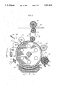
FIG. 2 is a simplified sectional illustration of electrostatic imaging apparatus constructed and operative in accordance with another preferred embodiment of the present invention;
FIG. 3A is a simplified, conceptual, sectional illustration of intermediate transfer member constructed and operative in accordance with a preferred embodiment of the present invention;
FIG. 3B is a simplified, conceptual, sectional illustration of a portion of a preferred embodiment of the intermediate transfer member of FIG. 3A;
FIG. 3C is a simplified, conceptual, sectional illustration of a portion of a second preferred embodiment of the intermediate transfer member of FIG. 3A;
FIG. 3D is an illustration of a preferred heater for the intermediate transfer member;
FIG. 3E is a detailed illustration of a portion of the embodiment of FIG. 3D;
FIG. 3F is an illustration of another preferred heater for the intermediate transfer member;
FIG. 3G is a detailed illustration of a portion of the embodiment of FIG. 3F;
FIG. 3H is a detailed illustration of a portion of an alternative of of FIG. 3F;
FIG. 3I is an illustration of another preferred heater for the intermediate transfer member;
FIG. 4 is a simplified sectional illustration of the manufacture of part of the apparatus of FIGS. 3A and 3B;
FIG. 5 is a graphical illustration of the relationship between pressure and deformation of the apparatus of FIG. 3B; and
FIG. 6 is a schematic illustration of a preferred electrical circuit for energizing the heater embodiments of FIG. 3F-3I.
DETAILED DESCRIPTION OF PREFERRED EMBODIMENTS
Reference is now made to FIG. 1, which illustrates electrostatic imaging apparatus constructed and operative in accordance with a preferred embodiment of the present invention. This and other embodiments of the invention are described for apparatus utilizing liquid toner with negatively charged toner particles, and for a write-white system. For positively charged toner particles and/or for a write-black system the magnitudes and or the polarities of the voltages are adjusted as is well known in the art. In a preferred embodiment of the invention the toner of
Example 1 of U.S. Pat. No. 4,794,651 which is incorporated herein by reference, is employed, but a variety of liquid toner types are useful in the practice of the invention.
As in conventional electrophotographic systems, the apparatus of FIG. 1 comprises a drum 10 arranged for rotation about an axle 12 in a direction generally indicated by arrow 14. The drum 10 is formed with a cylindrical photoconductive surface 16.
A corona discharge device 18 is operative to generally uniformly charge the photoconductor surface 16 with a positive charge. Continued rotation of the drum 10 brings the charged photoconductor surface 16 into image receiving relationship with an exposure unit including a lens 20, which focuses a desired image onto the charged photoconductive surface 16, selectively discharging the photoconductive surface, thus producing an electrostatic latent image thereon. Lens 20 may be the lens of a photocopier, as illustrated, or alternatively, for example, the lens of a laser printer.
Continued rotation of the drum 10 brings the charged photoconductive surface 16 bearing the electrostatic latent image into a development unit 22, including development electrodes 24, which is operative to apply a liquid developer comprising carrier liquid and toner particles to develop the electrostatic latent image.
In accordance with a preferred embodiment of the invention, following application of toner thereto, the photoconductive surface 16 passes a, typically positively charged, rotating roller 26, preferably rotating in a direction indicated by an arrow 28. Typically the spatial separation of the roller 26 from the photoconductor surface 16 is about 50 microns.
Preferably, the voltage on roller 26 is intermediate the voltages of the latent image areas and of the background areas on the photoconductive surface 16. Typical voltages are: roller 26: +300 to +500V, background area: +50V and latent image areas: up to +1000V.
It is appreciated that roller 26, rotating in the direction indicated by arrow 28, functions as a metering roller and reduces the thickness of liquid carrier on the photoconductive surface 16, as is known in the art.
In any event, the photoconductive surface 16, after passing the roller 26, should be relatively free of pigmented toner particles except in the region of the latent image.
Downstream of roller 26 there is preferably provided a rigidizing roller 30. The rigidizing roller 30 is preferably formed of a resilient polymeric material, such as conductive resilient polymeric materials as described in either or both of U.S. Pat. Nos. 3,959,574 and 3,863,603 and is preferably maintained in contacting or pressured relationship with the photoconductive surface 16.
In a preferred embodiment of the invention, the biased squeegee described in U.S. Pat. No. 4,286,039, the disclosure of which is incorporated herein by reference, is used as the roller 30. A negative voltage of about 1000 to 2000 Volts, preferably about 1500 Volts (for a write-white system), can be maintained on the squeegee. A corona discharge takes place and a current of approximately 50-100 microamperes for a drum width of 30 cm, flows from the squeegee. Roller 30 repels negatively charged pigmented toner particles and causes them to more closely approach the image areas of the photoconductive surface 16, thus compressing and rigidizing the toner image thereon.
Downstream of rigidizing roller 30 there is provided an intermediate transfer member 40, which rotates, as shown by arrow 41, in a sense opposite to that of drum 10, and is operative for receiving the toner image from surface 16 and for transferring the toner image to a receiving substrate 42, such as paper, which is supported by a roller 43.
The thrust of one aspect of the present invention lies in the structure and operation of the intermediate transfer member 40. Accordingly, in accordance with a preferred embodiment of the invention the intermediate transfer member 40 is configured and mounted with respect to the drum 10 for providing first transfer engagement between the intermediate transfer member 40 and the image bearing photoconductor surface 16 for transfer of an image from surface 16 to the intermediate transfer member 40 at a first pressure, producing radial deformation of the intermediate transfer member to a first deformation degree.
The configuration and arrangement of the intermediate transfer member 40, substrate 42 and roller 43 is preferably such as to provide second transfer engagement between the intermediate transfer member 40 and the substrate 42 for transfer of the image from the intermediate transfer member 40 to the substrate 42 at a second pressure, which exceeds the first pressure by a first multiple, producing radial deformation of the intermediate transfer member to a second deformation degree which exceeds the first deformation degree by a second multiple substantially less than the first multiple.
Additionally in accordance with a preferred embodiment of the present invention there is provided an intermediate transfer member characterized in that deformation thereof increases less than linearly with the application of increased pressure thereto. The structure of intermediate transfer members in accordance with the invention is described hereinbelow in detail.
Transfer of the image to intermediate transfer member 40 is preferably aided by providing electrification of the intermediate transfer member 40 to a voltage opposite that of the charged particles, although other methods known in the art may be employed. Subsequent transfer of the image to substrate 42 is preferably aided by heat and pressure, although other methods known in the art may be employed.
It has been noted that when the negatively biased squeegee roller of U.S. Pat. No. 4,286,039, with high negative voltage, is utilized as the roller 30, the positive voltage on the intermediate transfer member required to transfer the image thereto is sharply reduced, typically from about 1000 volts or more to about 500 to 600 volts or less. It is believed that this reduction is possibly due to a discharge of the charges in the image area of the photoconductive surface 16 by current from the squeegee roller.
Following transfer of the toner image to the intermediate transfer member, the photoconductive surface 16 is engaged by a cleaning roller assembly 50, including a pair of rollers 52, which typically rotate in opposite directions, and a nozzle 54. The cleaning roller assembly 50 is operative to scrub clean the surface 16. A cleaning material, such as liquid developer, may be supplied to the assembly 50 via nozzle 54. A suitable cleaning assembly is illustrated, in U.S. Pat. No. 4,439,035, the specification of which is incorporated herein by reference. Any residual charge left on the photoconductive surface 16 is removed by flooding the photoconductive surface 16 with light from a lamp 58.
Reference is now made to FIG. 2 which illustrates electrophotographic imaging apparatus constructed and operative in accordance with another preferred embodiment of the present invention. The apparatus of FIG. 2 shares many common elements with that of FIG. These elements are indicated by identical reference numerals, and for the sake of conciseness are not described herein a second time.
The embodiment of FIG. 2 differs from that of FIG. 1 in that a belt-type intermediate transfer member 70 is employed instead of a roller type as in the embodiment of FIG. Belt-type intermediate transfer members are well known in the art and are described, inter alia, in U.S. Pat. Nos. 3,893,761, 4,684,238 and 4,690,539, the disclosures of which are incorporated herein by reference.
Intermediate transfer member 70 is preferably charged so as to provide electrophoretic transfer of the image from the photoconductive surface 16 thereto. Within given limits, the efficiency of electrophoretic transfer of the image can be enhanced by increasing the potential difference between the photoconductive surface 16 and the intermediate transfer member 70. Increase in the potential difference between the photoconductive surface 16 and the intermediate transfer member 70 is limited, however, by the danger of severe electrical breakdown, which increases with an increase in potential difference.
Reference is now made to FIG. 3A which conceptually illustrates an intermediate transfer member 40 comprising a drum 80 having a generally cylindrical surface over which is tensioned a multi-layer intermediate transfer blanket 82, which is supported and tensioned by a blanket lockup mechanism 84. The electrical connections to the various voltage bearing portions of intermediate transfer blanket 82 are not shown, it being understood that they are achieved in a conventional manner using rotating contacts.
A preferred embodiment of multi-layer intermediate transfer blanket 82 is illustrated in FIG. 3B and comprises a substrate (backing layer) 90 with high temperature capabilities, preferably formed of Kapton (DuPont) polyimide film of thickness about 100 microns. Over the substrate 90 there is provided a blanket heater 92 preferably comprising a meandering ribbon conductor of Nichrome in a sandwich of Kapton. Blanket heater 92 has a total thickness of about 250 microns.
Normally one surface of blanket heater 92 has a slightly raised pattern due to the presence of the ribbon. Accordingly, it is preferable to arrange the blanket heater 92 such that the surface having the slightly raised pattern lies facing substrate 90, such that the opposite facing surface of blanket heater 92 is relatively smooth.
Blanket heater 92, in conjunction with the rest of the intermediate transfer blanket 82 operates to improve transfer of the image to the final substrate by heating the toner image. When a liquid toner for which the particles solvate the carrier at a temperature below the melting point of the toner particles is utilized in the practice of the invention, then the surface of the blanket should be heated to a temperature above the solvation temperature of the toner image, i.e. above the temperature at which the toner particles become tacky to the final substrate. For the preferred toner of example 1 of U.S. Pat. No. 4,794,651, preferably the blanket heater is operative to heat the image on the intermediate transfer member to about 100°-110° C.
To ensure even heating, the top of the blanket heater 92 is attached to a 100 micron thick aluminum foil 93. This foil also provides electromagnetic shielding of the image transfer regions of the imaging apparatus from interference produced by AC currents used to heat the blanket 92. The width of the Nichrome ribbon is chosen such that the ribbon covers a major portion, preferably over 80% of the blanket, to ensure even heating thereof.
Disposed over foil 93 is a three part sponge assembly layer 94, including a layer 96 of Kapton, typically of thickness 100 microns, a sponge layer 98, typically of thickness 300 microns and a fabric layer 100, typically formed of NOMEX (DuPont) and being typically of thickness 50 microns. The total sponge assembly layer thickness is typically 800 microns. Nomex is basically an aromatic polyamide and chars at 420° C.
The assembly layer 94 is preferably formed by blending the following materials, which form the sponge layer 98, in a two roll mill:
a. Fluorosilicone (FSE-2080 General Electric) 78.39%
b. Silicone (Silastic 4-2735 Dow Corning) 11.71%
c. Blowing Agent (#9038 Rhone Poulenc) 9%
d. Cross-Linker (Di Cumyl Peroxide) 0.9%
The blended material is formed into the assembly layer 94 by calendering between the fabric layer 100 and the Kapton layer 96 as illustrated in FIG. 4.
The total thickness of assembly layer 94 is typically about 670 microns after calendering. The assembly layer 94 is then preferably cured for 10 minutes under nitrogen at 170° C. and preferably in a jig to control the total swelling thereof to a total thickness of about 800 microns. After the curing, the assembly layer 94 undergoes a post-cure at 200° C. for four hours.
It is a particular feature of the present invention that the sponge assembly layer 94 allows conformity between surface 16 and intermediate transfer member 40 at the first transfer at a relatively low pressure, such as 100-500 gm/cm2 at a temperature of about 100-110° C., with relatively low deformation, such as 30-200 microns, overcoming any surface unevenness of the mating surfaces.
According to the present invention, the sponge assembly layer 94 is further characterized in that it undergoes relatively high pressure, such as 2000-4000 gm/cm2 at the second transfer with proportionately low deformation, greater then that at first transfer, preferably about 250 microns.
It is believed, that when the voltage on the rigidizing roller 30 is high enough to cause substantial compression of the image, generally at a value which also causes corona, the pressure at the first transfer surface can be increased up to about 500 gm/cm2, without image degradation.
Returning now to the structure of the intermediate transfer blanket 82, it is seen that over sponge assembly layer 94, there is provided a blanket 102, typically of about 1200 microns thickness.
Blanket 102 typically includes a layer 104 of relatively stiff sponge, over which is formed a layer 106 of nitrilic rubber. Blanket 102 is typically produced by removing the fabric layer from a three-ply Vulcan 714 offset printing blanket commercially available from Reeves Brothers, Inc..
Over printing blanket 102 there is provided a 2-3 micron thick layer 108 of nitrocellulose loaded with carbon black to provide a conductive layer for the high voltage applied to the intermediate transfer member. This layer has an end to end resistance of about 20-30 kohm, but since the current drawn to the drum is only 50-100 microamperes, the voltage drop on the layer is less than 3 volts out of the applied voltage of 500-600 volts.
An outer layer 110 typically comprises a 2-3 micron thick layer of silicone rubber, such as Syl-Off 294, which acts as a release layer.
An alternative preferred embodiment of a blanket 114 in accordance with the invention is shown conceptually in cross section in FIG. 3C. In this embodiment the lowest level of the blanket is a Kapton layer 116, typically 100 microns thick, which is similar to layer 96 of FIG. 3B. The next layer is a sponge layer 118, functionally similar to sponge layer 98 shown in FIG. 3B and typically 300 microns thick.
Situated above layer 118, is a heater 120, with typical thickness 650 microns, whose structure and manufacture will be described later. An acrylic rubber layer 122 is formed onto the heater 120 and preferably penetrates therein. A conducting layer 124 and a release layer 126 complete the blanket. Additional spacer material 128, typically of Kapton may be added below the blanket, if additional blanket thickness is required. Alternatively the Kapton layer 116 may be thicker than the indicated thickness.
As is shown in FIGS. 3D and 3E, heater 120 may be formed by weaving heater wire 130 forming the woof and twisted thread 132 as the warp. In a typical application for forming a blanket with a 30 cm. axial dimension (when wrapped on drum 80) and a 41 cm circumferential dimension, wire 130 is formed of a 300 micron diameter copper core with a 10 micron lacquer coating, for a total diameter of 320 microns. Thread 132 is preferably of twisted Nomex thread with a nominal diameter of 320 microns. When wire 130 and thread 132 are formed into heater 120, the overall heater thickness and the center to center spacing of the wires are each approximately 650 microns.
Two connection wires 134 for energizing the heater are extensions of the heater wires 130. A Nomex cloth extension 136 is provided beyond each end of the heater portion of the heater 120.
The unconventional structure of the blanket heater 120 of FIGS. 3D and 3E enables its placement over sponge layer 118. It will be noted that heater 92 of the embodiment illustrated in FIG. 3B is placed below the sponge layer 98. Since heater 92 is stiff in both the circumferential and the axial directions, placement of the heater 92 above the sponge layer would substantially shield the blanket-photoconductor and blanket-final substrate image transfer interfaces from the compression properties of the sponge assembly 94.
Heater 120 on the other hand is stiff in the axial direction, but it is pliable in the circumferential direction and thus transmits the pressure at the respective interfaces to the sponge layer. Placing the heater closer to the transfer surface allows for a lower heater temperature for the same surface temperature, and allows for the sponge layer to be much cooler. The pressure along lines in the axial direction is substantially constant compared to the variations in the circumferential direction; it would be perfectly constant were the transfer surfaces perfect and the mechanical tolerances were equal to zero, the tolerances and imperfections cause some small variation in deformation and hence of pressure along the axial lines.
An alternative preferred heater 150 is shown in FIGS. 3F and 3G. In this embodiment two inputs 151 and 152 are at the same end of the heater wires are threaded in a paired spaced relationship as shown in FIGS. 3F and 3G. Additional input 153 is electrically connected to the other end of the heater such that the current path between inputs 151 and 153 is substantially the same length as that between inputs 152 and 153.
The heater 150 is preferably energized with the circuit of FIG. 6, wherein the input to a transformer 157 is an AC voltage and a pair of output terminals 154 and 156 of transformer 157 are at the same voltage and at opposite phases with respect to a third terminal 155. Terminals 154, 155 and 156 are electrically insulated from the AC input.
In operation, heater 150 is incorporated in a blanket, and installed in the apparatus of FIG. 1. Terminals 154 and 156 are electrically connected to inputs 151 and 152, and additional input 153 is connected to terminal 155. Alternatively the wires can be "crossed" at each reversal of the wire direction (at the edges of the heater). One such crossing is shown in FIG. 3H.
Alternatively, wire 153 and terminal 155 could be externally electrically connected to the bias layer 124. Alternatively wire 153 and terminal 153 could be connected to a source of high voltage in order to provide a field at the transfer regions and layer 124 could be omitted. For this last alternative, a substantially higher voltage would be required to provide the field due to the greater distance of the heater from the transfer surface.
An alternative preferred heater 160 is shown in FIG. 3I. In this embodiment the wire and thread are woven in a similar manner to that of the embodiment shown in FIG. 3D. Two connection wires 162 and 164 for energizing the heater are extensions of the heater wire and an additional wire 168 is electrically connected to the center of the length of wire used to form the heater. In operation the heater is energized by connecting wires 162 and 164 to terminals 154 and 156, and connecting wire 168 to terminal 155.
Alternatively, wire 168 and terminal 155 could be externally electrically connected to the bias layer 124.
Layer 122 should preferably have the following properties:
(a) High Electrical resistivity at the operating temperature;
(b) High resilience, especially at the second transfer (to the receiving substrate 42), due to the high pressures and deformation at that transfer;
(c) The proper hardness- Approximately 40 Shore A;
(d) It should be castable and bondable to subsequent layers;
(e) It should have high strength, especially in tension and tear; and
(f) It should be stable under temperature and pressure, that is to say, its pressure-deformation curve should remain relatively stable after repeated compression and release at the temperature of operation.
Blanket 114 is preferably manufactured using the following process, although other manufacturing methods may suggest themselves to those knowledgeable in the art:
STEP I-Forming of layer 122 onto heater 120.
100 parts by weight of HYTEMP 4051 Acrylic rubber compound manufactured by B.F. Goodrich is mixed in a two roll mill with 15 parts of very fine silica, 4 parts sodium stearate and 2 parts NPC-50 crosslinker, until the mixture is smooth. The silica is added to increase the electrical resistivity, mechanical cohesiveness and strength of the final polymer. A heater 120 is placed in a mold coated with silicone oil, and is covered with the rubber/silica mixture. The mixture is cured in the mold to a final thickness of 1500 microns at a temperature of 180° C. for 15 minutes. The mold is cooled and resulting sheet is removed. It will be appreciated that this sheet comprises heater 120 and rubber layer 122 formed into an integral unit due to the filling of the heater by the rubber/silica mixture before curing.
STEP II-Forming of the sponge layer 118.
The procedure described above for the manufacture of the sponge assembly 94 (described in conjunction with FIG. 3B) is followed for this step, with the exception that the fabric layer 100 of that procedure is replaced by the double layer 120 and 122 produced by Step I, immediately above. The spacing of the rollers, and the thickness of the sizing jig are adjusted to account for the increased thickness of the new material.
In an alternative and preferred embodiment of the invention, the following procedure is followed:
100 parts by weight of HYTEMP 4051 Acrylic rubber compound manufactured by B.F. Goodrich is mixed in a two roll mill with 15 parts of very fine silica, 4 parts of sodium stearate, 2 parts of NPC-50 crosslinker and 11 to 33 parts by weight of Blowing Agent (#9038 Rhone Poulenc) until the mixture is smooth. The silica is added to increase the cohesiveness of the sponge. 1 part of the mixture is mixed with preferably 2 parts of a solvent, preferably acetone or MEK, in order to reduce its viscosity.
The blended material is calendered between the double layer 120 and 122 and the Kapton layer 116 essentially as described above and illustrated in FIG. 4, for the manufacture of sponge layer 98.
The total thickness of the resulting multilayer sheet 118, 122, 120 and 116 after calendering will depend on the amount of blowing agent used and can be found by simple experiment.
The triple layer is cured, preferably in a jig to control the total swelling thereof, at a temperature of 180° C. for 15 minutes. The mold is cooled and resulting sheet is removed. It will be appreciated that this sheet comprises all four layers formed into an integral unit. In an alternative embodiment of the invention Kapton layer 116 can be replaced by Nomex cloth, since the acrylic rubber layers together with the Nomex cloth appear to give sufficient structural strength to the blanket.
STEP III-Adding the conducting (bias) layer 124.
15 parts of HYTEMP 4051, 100 parts of MEK (methylmetacrilate), 6 parts of carbon black (Printex XE-2 manufactured by Degussa) and 2 parts of NPC-50 cross-linker are mixed in a cooled ball attritor for 12 hours. This material is wire coated onto the surface of layer 122 and cured at 150° C. for 15 minutes to form an approximately 2 micron thick conducting layer with a resistance of between 10-100 kohm/square, preferably 30-50 kohm/square, bonded to layer 122.
STEP IV-Post Curing
Post curing of the HYTEMP 4051 is not part of the process as recommended by the manufacturer. It has been found that the stability of the material under compression cycling at operating temperature was improved by the addition of a 180 degree C., 12 hour post curing step.
STEP V-Adding the silicone release layer 126.
100 parts of Syl-off 294 is diluted 1:1 with Isopar L. 15 parts of Syl-off 297 ancorning agent and 5 parts of Dow Corning 176 cross-linker are added to the mixture. This mixture is wire coated on to the surface of conducting layer 124 and air cured at 110° C. for 10 minutes to give 5-6 micron thick layer.
FIG. 5 is a graph which illustrates the approximate desired pressure/deformation characteristics of the intermediate transfer member structures shown in FIG. 3B-3I, under ordinary use conditions in intermediate transfer apparatus according to a preferred embodiment of the present invention.
The invention is illustrated herein with examples employing a single developer station. The invention is especially useful in imaging systems with a multiple of development stations preferably with different color liquid developers, or a single station in which the liquid developer is changed between colors. For either of these systems each individual color image may be transferred to the final substrate from the ITM individually, or the colored images may be transferred sequentially to the ITM and then transferred to the substrate together. Color imaging equipment is described in U.S. Pat. Nos. 4,788,572; 4,690,539 and 3,900,003.
It will be appreciated by persons skilled in the art that the present invention is not limited by what has been particularly shown and described hereinabove. Rather the scope of the present invention is defined only by the claims which follow:

Claims (15)

We claim:
1. An imaging system comprising:
an image bearing surface;
an intermediate transfer member operative for transfer of liquid toner images from said image bearing surface to a substrate;
means for providing first transfer engagement between said intermediate transfer member and said image bearing surface for transfer of a liquid toner image from said image bearing surface to said intermediate transfer member at a first pressure, producing deformation of the intermediate transfer member to a first deformation degree; and
means for providing second transfer engagement between said intermediate transfer member and said substrate for transfer of said liquid toner image from said intermediate transfer member to said substrate at a second pressure, producing deformation of the intermediate transfer member to a second deformation degree;
wherein the second pressure exceeds the first pressure by a first multiple and the second deformation degree exceeds the first deformation degree by a second multiple, substantially less than said first multiple.
2. A system according to claim 1 and wherein said intermediate transfer member comprises a blanket heater operative to heat the liquid toner image thereon prior to said second transfer engagement.
3. A system according to claim 1 and wherein said intermediate transfer member comprises a conductive layer operative to apply an electric field to said liquid toner image to enhance transfer of said liquid toner image from said image bearing surface to said intermediate transfer member.
4. A system according to claim 2 and wherein said blanket heater is operative to heat said liquid toner image to a temperature sufficient to enhance transfer of said liquid toner image from said intermediate transfer member to said substrate.
5. A system according to claim 2 wherein said first and second pressures are substantially constant along particular lines upon said first and second transfer engagements on said intermediate transfer member, and wherein said heater is formed of thin wires along said lines.
6. An imaging system according to claim 1, wherein said intermediate transfer member comprises:
an outward facing transfer surface;
a compressible layer;
a backing layer; and
a heating layer,
said heating layer being disposed intermediate said backing layer and said transfer surface.
7. An imaging system according to claim 6 and also comprising a resilient layer, said heating layer being disposed intermediate said compressible layer and said resilient layer.
8. An imaging system according to claim 1, wherein said intermediate transfer member comprises:
at least one resilient layer; and
a backing layer disposed away from said image bearing surface,
wherein said at least one resilient layer includes a heating layer.
9. A system according to claim 8 and wherein said heating layer is internal to said at least one resilient layer.
10. A system according to claim 6 and wherein said heating layer is operative to heat said liquid toner image to a temperature sufficient to enhance transfer of said liquid toner image from said intermediate transfer member to said substrate.
11. A system according to claim 6 and wherein the pressure is substantially constant along particular lines upon said first and second transfer engagements on said intermediate transfer member, and wherein said heating layer is formed of thin wires along said lines.
12. A system according to claim 6 and wherein said heating layer is disposed intermediate said backing layer and said compressible layer.
13. A system according to claim 6 and wherein said heating layer is disposed intermediate said transfer surface and said compressible layer.
14. A system according to claim 1 and wherein said intermediate transfer member comprises first an second resilient layers having different stiffnesses.
15. A system according to claim 6 wherein only resilient materials are placed between said heater layer and said transfer surface.
US07/393,649 1989-02-06 1989-08-14 Image transfer apparatus including a compliant transfer member Expired - Lifetime US5047808A (en)

Priority Applications (16)

Application Number Priority Date Filing Date Title
US07/393,649 US5047808A (en) 1989-02-06 1989-08-14 Image transfer apparatus including a compliant transfer member
EP93203341A EP0584893B1 (en) 1989-08-14 1990-04-17 Image transfer apparatus and method
EP97201407A EP0791860A3 (en) 1989-08-14 1990-04-17 Organic photoconductor
DE69027777T DE69027777T2 (en) 1989-08-14 1990-04-17 IMAGE TRANSFER DEVICE AND METHOD
EP90907505A EP0487530B1 (en) 1989-08-14 1990-04-17 Image transfer apparatus and method
CA002064816A CA2064816C (en) 1989-08-14 1990-04-17 Image transfer apparatus and method
DE1990631779 DE69031779T2 (en) 1989-08-14 1990-04-17 Image transmission device and method
JP50670790A JP3086858B2 (en) 1989-08-14 1990-04-17 Image transfer apparatus and method
PCT/NL1990/000049 WO1991003006A1 (en) 1989-08-14 1990-04-17 Image transfer apparatus and method
JP51093290A JP3263069B2 (en) 1989-08-14 1990-07-23 Imaging method and apparatus
PCT/NL1990/000099 WO1991003007A1 (en) 1989-08-14 1990-07-23 Imaging method and apparatus
EP90911661A EP0486534B1 (en) 1989-08-14 1990-07-23 Imaging method and apparatus
US07/829,025 US5276492A (en) 1989-08-14 1990-07-23 Imaging method and apparatus
CA002064848A CA2064848C (en) 1989-08-14 1990-07-23 Imaging method and apparatus
DE69013000T DE69013000T2 (en) 1989-08-14 1990-07-23 METHOD AND DEVICE FOR PRODUCING IMAGES.
HK137595A HK137595A (en) 1989-08-14 1995-08-31 Imaging method and apparatus

Applications Claiming Priority (2)

Application Number Priority Date Filing Date Title
US07/306,065 US4984025A (en) 1989-02-06 1989-02-06 Imaging system with intermediate transfer member
US07/393,649 US5047808A (en) 1989-02-06 1989-08-14 Image transfer apparatus including a compliant transfer member

Related Parent Applications (1)

Application Number Title Priority Date Filing Date
US07/306,065 Continuation-In-Part US4984025A (en) 1989-01-04 1989-02-06 Imaging system with intermediate transfer member

Related Child Applications (1)

Application Number Title Priority Date Filing Date
US07/829,025 Continuation-In-Part US5276492A (en) 1989-08-14 1990-07-23 Imaging method and apparatus

Publications (1)

Publication Number Publication Date
US5047808A true US5047808A (en) 1991-09-10

Family

ID=26974940

Family Applications (1)

Application Number Title Priority Date Filing Date
US07/393,649 Expired - Lifetime US5047808A (en) 1989-02-06 1989-08-14 Image transfer apparatus including a compliant transfer member

Country Status (1)

Country Link
US (1) US5047808A (en)

Cited By (42)

* Cited by examiner, † Cited by third party
Publication number Priority date Publication date Assignee Title
US5136334A (en) * 1991-05-17 1992-08-04 Hewlett-Packard Company Method and apparatus for preparing liquid tone for direct transfer to the media during electrophotographic printing
US5335054A (en) * 1989-02-06 1994-08-02 Spectrum Sciences B.V. Image transfer apparatus including intermediate transfer blanket
US5337129A (en) * 1993-10-27 1994-08-09 Xerox Corporation Intermediate transfer component coatings of ceramer and grafted ceramer
US5414498A (en) * 1993-09-14 1995-05-09 Delphax Systems Liquid/dry toner imaging system
WO1996013760A1 (en) * 1994-10-28 1996-05-09 Indigo N.V. Imaging apparatus and toner therefor
US5530532A (en) * 1993-09-03 1996-06-25 Minolta Co., Ltd. Image forming apparatus using intermediate transfer member having surface roughness to toner size ratio
US5592269A (en) * 1993-03-26 1997-01-07 Indigo N.V. Imaging system having an intermediate transfer member
US5608503A (en) * 1994-01-21 1997-03-04 Minolta Co., Ltd. Image forming apparatus using an intermediate transfer member, an intermediate transfer member and image forming method
US5610694A (en) * 1993-01-11 1997-03-11 Indigo N.V. Latent development apparatus for use in electrophotographic imaging system
US5612773A (en) * 1995-08-18 1997-03-18 Xerox Corporation Intermediate transfer member
US5728502A (en) * 1996-03-12 1998-03-17 Minnesota Mining And Manufacturing Company Imaging medium, method of imaging said medium, and image-bearing medium
US5745829A (en) 1989-01-04 1998-04-28 Indigo N.V. Imaging apparatus and intermediate transfer blanket therefor
US5777296A (en) * 1996-09-16 1998-07-07 Bell; Jerome Electrically heated garment
US5784677A (en) * 1992-03-25 1998-07-21 Toray Industries Inc. Electrophotographic printer and printing method using specific intermediate transfer drum and transfer roller arrangement
US5864353A (en) * 1995-02-03 1999-01-26 Indigo N.V. C/A method of calibrating a color for monochrome electrostatic imaging apparatus
US5893016A (en) * 1995-04-30 1999-04-06 Indigo N.V. Apparatus for printing images on generally cylindrical objects
US5894796A (en) * 1997-08-01 1999-04-20 Heidelberger Druckmaschinen Ag Printing unit for a web-fed rotary printing press
US5908729A (en) * 1995-04-07 1999-06-01 Indigo N.V. Printing on transparent film
US5915152A (en) * 1995-03-23 1999-06-22 Indigo N.V. Imaging device having liquid toner applicator using a nozzle
US5923929A (en) * 1994-12-01 1999-07-13 Indigo N.V. Imaging apparatus and method and liquid toner therefor
US5965314A (en) * 1997-04-03 1999-10-12 Minnesota Mining And Manufacturing Company Intermediate transfer element for liquid electrophotography
US5972548A (en) * 1995-04-16 1999-10-26 Indigo N.V. Process for forming an image on ceramic substrates
US5987284A (en) * 1997-09-29 1999-11-16 Xerox Corporation Method and apparatus for removing fluid from the surface of a liquid developed image
US6108513A (en) * 1995-04-03 2000-08-22 Indigo N.V. Double sided imaging
US6163676A (en) * 1995-09-08 2000-12-19 Indigo N.V. Imaging apparatus and improved exit device therefor
US6212353B1 (en) 1996-12-03 2001-04-03 Indigo N.V. Method and apparatus for cleaning an image transfer member
USRE37859E1 (en) 1991-07-09 2002-09-24 Indigo N.V. Development control system
US6551716B1 (en) 1997-06-03 2003-04-22 Indigo N.V. Intermediate transfer blanket and method of producing the same
US6584294B1 (en) 1998-11-25 2003-06-24 Hewlett-Packard Indigo B.V. Fuser and intermediate transfer drums
US6623902B1 (en) 1991-03-28 2003-09-23 Hewlett-Packard Indigo B.V. Liquid toner and method of printing using same
US6861193B1 (en) 2000-05-17 2005-03-01 Hewlett-Packard Indigo B.V. Fluorescent liquid toner and method of printing using same
US20050217522A1 (en) * 2004-03-24 2005-10-06 Man Roland Druckmaschine Ag Rolls and cylinders with a steel core for offset presses
US6969543B1 (en) 1995-08-17 2005-11-29 Hewlett-Packard Development Company, L.P. Intermediate transfer blanket and method of producing the same
US6979523B1 (en) 1995-04-07 2005-12-27 Hewlett-Packard Development Company, Lp Toner material and method utilizing same
US7092667B1 (en) 2000-10-13 2006-08-15 Hewlett-Packard Development Company, L.P. Fuser and intermediate transfer drums
US20070009684A1 (en) * 2003-03-31 2007-01-11 Kabushiki Kaisha Meiji Gomu Kasei Image transfer sheet
US7977023B2 (en) 2007-07-26 2011-07-12 Hewlett-Packard Development Company, L.P. Ink formulations and methods of making ink formulations
US20120132093A1 (en) * 2010-03-30 2012-05-31 Annan Arraf Image transfer blanket
US9096052B2 (en) 2011-01-31 2015-08-04 Hewlett-Packard Development Company, L.P. Printers, methods, and apparatus to form an image on a print substrate
US9409384B2 (en) 2013-07-24 2016-08-09 Hewlett-Packard Development Company, L.P. Printers, methods and apparatus to form an image on a print substrate
CN106218201A (en) * 2016-07-27 2016-12-14 广东顺德意达电子薄膜器件有限公司 Electrostatic printing techniques application in the intelligence of decoration panel makes and decoration panel and preparation method thereof
US11656563B2 (en) 2019-08-14 2023-05-23 Fujifilm Business Innovation Corp. Jacket, transfer device, and image forming device

Citations (30)

* Cited by examiner, † Cited by third party
Publication number Priority date Publication date Assignee Title
US415856A (en) * 1889-11-26 Charles e
US3591276A (en) * 1967-11-30 1971-07-06 Xerox Corp Method and apparatus for offset xerographic reproduction
US3816929A (en) * 1971-11-15 1974-06-18 Rambold Kg F Measuring instrument
US3862848A (en) * 1971-12-24 1975-01-28 Australia Res Lab Transfer of color images
US3863603A (en) * 1974-01-07 1975-02-04 Ibm Magnetic brush roll having resilient polymeric surface
US3893761A (en) * 1972-11-02 1975-07-08 Itek Corp Electrophotographic toner transfer and fusing apparatus
US3900003A (en) * 1973-06-15 1975-08-19 Canon Kk Liquid developing device for electrophotography
US3959574A (en) * 1974-04-26 1976-05-25 Xerox Corporation Biasable member and method for making
US3983287A (en) * 1971-11-22 1976-09-28 Minnesota Mining And Manufacturing Company Compressible printing blanket
US4286039A (en) * 1979-05-15 1981-08-25 Savin Corporation Method and apparatus for removing excess developing liquid from photoconductive surfaces
JPS56164368A (en) * 1980-05-22 1981-12-17 Konishiroku Photo Ind Co Ltd Intermediate transfer medium for toner image
US4439035A (en) * 1978-11-09 1984-03-27 Savin Corporation Copier cleaning system incorporating resilient noncellular sealing roller
NL8301978A (en) * 1983-06-03 1985-01-02 Oce Nederland Bv Electrostatic photocopier - transfers toner image by internal rubber belt with eddy current braking preventing image elongation
US4518976A (en) * 1982-11-17 1985-05-21 Konishiroku Photo Industry Co., Ltd. Recording apparatus
US4531825A (en) * 1981-11-25 1985-07-30 Konishiroku Photo Industry Co., Ltd. Electrostatic reproducing apparatus having an intermediate toner image transfer member
EP0176143A1 (en) * 1984-09-24 1986-04-02 Océ-Nederland B.V. Optical imaging system for a copying machine
US4585319A (en) * 1982-11-29 1986-04-29 Konishiroku Photo Industry Co., Ltd. Recording apparatus for electrostatic images
JPS628168A (en) * 1985-07-05 1987-01-16 Konishiroku Photo Ind Co Ltd Image forming method
JPS62134671A (en) * 1985-12-09 1987-06-17 Canon Inc Image recorder
JPS62134673A (en) * 1985-12-09 1987-06-17 Canon Inc Image recorder
US4684238A (en) * 1986-06-09 1987-08-04 Xerox Corporation Intermediate transfer apparatus
US4690539A (en) * 1986-05-27 1987-09-01 Xerox Corporation Transfer apparatus
US4708460A (en) * 1986-07-25 1987-11-24 Xerox Corporation Simultaneous transfer and fusing in electrophotography
US4743939A (en) * 1987-06-01 1988-05-10 Xerox Corporation Intermediate transfer apparatus
US4788572A (en) * 1985-10-25 1988-11-29 Colorocs Corporation Belt controls for a print engine for color electrophotography
DE3816929A1 (en) * 1987-05-19 1988-12-08 Citizen Watch Co Ltd PRINTER
US4791275A (en) * 1986-04-07 1988-12-13 Imi-Tech Corporation High temperature compliant roll particularly adapted for xerography
US4794651A (en) * 1984-12-10 1988-12-27 Savin Corporation Toner for use in compositions for developing latent electrostatic images, method of making the same, and liquid composition using the improved toner
US4796048A (en) * 1987-11-23 1989-01-03 Xerox Corporation Resilient intermediate transfer member and apparatus for liquid ink development
EP0318078A1 (en) * 1987-11-11 1989-05-31 Océ-Nederland B.V. Device for transferring a powder image to a receiving material and fixing the powder image thereon

Patent Citations (32)

* Cited by examiner, † Cited by third party
Publication number Priority date Publication date Assignee Title
US415856A (en) * 1889-11-26 Charles e
US3591276A (en) * 1967-11-30 1971-07-06 Xerox Corp Method and apparatus for offset xerographic reproduction
US3816929A (en) * 1971-11-15 1974-06-18 Rambold Kg F Measuring instrument
US3983287A (en) * 1971-11-22 1976-09-28 Minnesota Mining And Manufacturing Company Compressible printing blanket
US3862848A (en) * 1971-12-24 1975-01-28 Australia Res Lab Transfer of color images
US3893761A (en) * 1972-11-02 1975-07-08 Itek Corp Electrophotographic toner transfer and fusing apparatus
US3900003A (en) * 1973-06-15 1975-08-19 Canon Kk Liquid developing device for electrophotography
US3863603A (en) * 1974-01-07 1975-02-04 Ibm Magnetic brush roll having resilient polymeric surface
US3959574A (en) * 1974-04-26 1976-05-25 Xerox Corporation Biasable member and method for making
US4439035A (en) * 1978-11-09 1984-03-27 Savin Corporation Copier cleaning system incorporating resilient noncellular sealing roller
US4286039A (en) * 1979-05-15 1981-08-25 Savin Corporation Method and apparatus for removing excess developing liquid from photoconductive surfaces
JPS56164368A (en) * 1980-05-22 1981-12-17 Konishiroku Photo Ind Co Ltd Intermediate transfer medium for toner image
US4531825A (en) * 1981-11-25 1985-07-30 Konishiroku Photo Industry Co., Ltd. Electrostatic reproducing apparatus having an intermediate toner image transfer member
US4518976A (en) * 1982-11-17 1985-05-21 Konishiroku Photo Industry Co., Ltd. Recording apparatus
US4585319A (en) * 1982-11-29 1986-04-29 Konishiroku Photo Industry Co., Ltd. Recording apparatus for electrostatic images
NL8301978A (en) * 1983-06-03 1985-01-02 Oce Nederland Bv Electrostatic photocopier - transfers toner image by internal rubber belt with eddy current braking preventing image elongation
US4891668A (en) * 1984-09-24 1990-01-02 Oce-Nederland B.V. Optical imaging system for a copying machine
EP0176143A1 (en) * 1984-09-24 1986-04-02 Océ-Nederland B.V. Optical imaging system for a copying machine
US4794651A (en) * 1984-12-10 1988-12-27 Savin Corporation Toner for use in compositions for developing latent electrostatic images, method of making the same, and liquid composition using the improved toner
JPS628168A (en) * 1985-07-05 1987-01-16 Konishiroku Photo Ind Co Ltd Image forming method
US4788572A (en) * 1985-10-25 1988-11-29 Colorocs Corporation Belt controls for a print engine for color electrophotography
JPS62134673A (en) * 1985-12-09 1987-06-17 Canon Inc Image recorder
JPS62134671A (en) * 1985-12-09 1987-06-17 Canon Inc Image recorder
US4791275A (en) * 1986-04-07 1988-12-13 Imi-Tech Corporation High temperature compliant roll particularly adapted for xerography
US4690539A (en) * 1986-05-27 1987-09-01 Xerox Corporation Transfer apparatus
US4684238A (en) * 1986-06-09 1987-08-04 Xerox Corporation Intermediate transfer apparatus
US4708460A (en) * 1986-07-25 1987-11-24 Xerox Corporation Simultaneous transfer and fusing in electrophotography
DE3816929A1 (en) * 1987-05-19 1988-12-08 Citizen Watch Co Ltd PRINTER
US4912514A (en) * 1987-05-19 1990-03-27 Citizen Watch Co., Ltd. Electrophotographic printer
US4743939A (en) * 1987-06-01 1988-05-10 Xerox Corporation Intermediate transfer apparatus
EP0318078A1 (en) * 1987-11-11 1989-05-31 Océ-Nederland B.V. Device for transferring a powder image to a receiving material and fixing the powder image thereon
US4796048A (en) * 1987-11-23 1989-01-03 Xerox Corporation Resilient intermediate transfer member and apparatus for liquid ink development

Non-Patent Citations (8)

* Cited by examiner, † Cited by third party
Title
Copy of International Search Report. *
English Abstract of Japanese Publication No. 62 81681. *
English Abstract of Japanese Publication No. 62-81681.
English Translation of Claim 4 of Netherlands Publication No. 8301978. *
English Translation of Japanese Publication No. 62 134671. *
English Translation of Japanese Publication No. 62 134673. *
English Translation of Japanese Publication No. 62-134671.
English Translation of Japanese Publication No. 62-134673.

Cited By (56)

* Cited by examiner, † Cited by third party
Publication number Priority date Publication date Assignee Title
US5745829A (en) 1989-01-04 1998-04-28 Indigo N.V. Imaging apparatus and intermediate transfer blanket therefor
US5335054A (en) * 1989-02-06 1994-08-02 Spectrum Sciences B.V. Image transfer apparatus including intermediate transfer blanket
US6070042A (en) * 1989-02-06 2000-05-30 Indigo N.V. Image transfer apparatus incorporating an integral heater
US6623902B1 (en) 1991-03-28 2003-09-23 Hewlett-Packard Indigo B.V. Liquid toner and method of printing using same
US20040023143A1 (en) * 1991-03-28 2004-02-05 Hewlett-Packard Indigo B.V. Liquid toner and method of printing using same
US7078141B2 (en) 1991-03-28 2006-07-18 Hewlett-Packard Development Company, Lp Liquid toner and method of printing using same
US5136334A (en) * 1991-05-17 1992-08-04 Hewlett-Packard Company Method and apparatus for preparing liquid tone for direct transfer to the media during electrophotographic printing
USRE37859E1 (en) 1991-07-09 2002-09-24 Indigo N.V. Development control system
US5784677A (en) * 1992-03-25 1998-07-21 Toray Industries Inc. Electrophotographic printer and printing method using specific intermediate transfer drum and transfer roller arrangement
US5610694A (en) * 1993-01-11 1997-03-11 Indigo N.V. Latent development apparatus for use in electrophotographic imaging system
US5592269A (en) * 1993-03-26 1997-01-07 Indigo N.V. Imaging system having an intermediate transfer member
US5530532A (en) * 1993-09-03 1996-06-25 Minolta Co., Ltd. Image forming apparatus using intermediate transfer member having surface roughness to toner size ratio
US5414498A (en) * 1993-09-14 1995-05-09 Delphax Systems Liquid/dry toner imaging system
US5337129A (en) * 1993-10-27 1994-08-09 Xerox Corporation Intermediate transfer component coatings of ceramer and grafted ceramer
US5608503A (en) * 1994-01-21 1997-03-04 Minolta Co., Ltd. Image forming apparatus using an intermediate transfer member, an intermediate transfer member and image forming method
WO1996013760A1 (en) * 1994-10-28 1996-05-09 Indigo N.V. Imaging apparatus and toner therefor
US20080056779A1 (en) * 1994-10-28 2008-03-06 Benzion Landa Imaging Apparatus and Improved Toner Therefor
US7647008B2 (en) 1994-10-28 2010-01-12 Hewlett-Packard Indigo B.V. Imaging apparatus and improved toner therefor
US7678525B2 (en) 1994-10-28 2010-03-16 Hewlett-Packard Development Company, L.P. Imaging apparatus and improved toner therefor
US20030068570A1 (en) * 1994-10-28 2003-04-10 Benzion Landa Imaging apparatus and improved toner therefor
US20030059701A1 (en) * 1994-10-28 2003-03-27 Benzion Landa Imaging apparatus and improved toner therefor
US6479205B1 (en) 1994-10-28 2002-11-12 Indigo N.V. Imaging apparatus and toner therefor
US7354691B2 (en) 1994-10-28 2008-04-08 Hewlett-Packard Development Company, L.P. Imaging apparatus and improved toner therefor
US5923929A (en) * 1994-12-01 1999-07-13 Indigo N.V. Imaging apparatus and method and liquid toner therefor
US5864353A (en) * 1995-02-03 1999-01-26 Indigo N.V. C/A method of calibrating a color for monochrome electrostatic imaging apparatus
US5915152A (en) * 1995-03-23 1999-06-22 Indigo N.V. Imaging device having liquid toner applicator using a nozzle
US6108513A (en) * 1995-04-03 2000-08-22 Indigo N.V. Double sided imaging
US6979523B1 (en) 1995-04-07 2005-12-27 Hewlett-Packard Development Company, Lp Toner material and method utilizing same
US5908729A (en) * 1995-04-07 1999-06-01 Indigo N.V. Printing on transparent film
US5972548A (en) * 1995-04-16 1999-10-26 Indigo N.V. Process for forming an image on ceramic substrates
US5893016A (en) * 1995-04-30 1999-04-06 Indigo N.V. Apparatus for printing images on generally cylindrical objects
US6969543B1 (en) 1995-08-17 2005-11-29 Hewlett-Packard Development Company, L.P. Intermediate transfer blanket and method of producing the same
US5612773A (en) * 1995-08-18 1997-03-18 Xerox Corporation Intermediate transfer member
US6163676A (en) * 1995-09-08 2000-12-19 Indigo N.V. Imaging apparatus and improved exit device therefor
US5728502A (en) * 1996-03-12 1998-03-17 Minnesota Mining And Manufacturing Company Imaging medium, method of imaging said medium, and image-bearing medium
US6045920A (en) * 1996-03-12 2000-04-04 3M Innovative Properties Company Imaging medium, method of imaging said medium, and image-bearing medium
US5777296A (en) * 1996-09-16 1998-07-07 Bell; Jerome Electrically heated garment
US6212353B1 (en) 1996-12-03 2001-04-03 Indigo N.V. Method and apparatus for cleaning an image transfer member
US5965314A (en) * 1997-04-03 1999-10-12 Minnesota Mining And Manufacturing Company Intermediate transfer element for liquid electrophotography
US6551716B1 (en) 1997-06-03 2003-04-22 Indigo N.V. Intermediate transfer blanket and method of producing the same
US5894796A (en) * 1997-08-01 1999-04-20 Heidelberger Druckmaschinen Ag Printing unit for a web-fed rotary printing press
US5987284A (en) * 1997-09-29 1999-11-16 Xerox Corporation Method and apparatus for removing fluid from the surface of a liquid developed image
US6584294B1 (en) 1998-11-25 2003-06-24 Hewlett-Packard Indigo B.V. Fuser and intermediate transfer drums
US6861193B1 (en) 2000-05-17 2005-03-01 Hewlett-Packard Indigo B.V. Fluorescent liquid toner and method of printing using same
US7092667B1 (en) 2000-10-13 2006-08-15 Hewlett-Packard Development Company, L.P. Fuser and intermediate transfer drums
US7754313B2 (en) * 2003-03-31 2010-07-13 Kabushiki Kaisha Meiji Gomu Kasei Image transfer sheet
US20070009684A1 (en) * 2003-03-31 2007-01-11 Kabushiki Kaisha Meiji Gomu Kasei Image transfer sheet
US7861653B2 (en) * 2004-03-24 2011-01-04 Manroland Ag Rolls and cylinders with a steel core for offset presses
US20050217522A1 (en) * 2004-03-24 2005-10-06 Man Roland Druckmaschine Ag Rolls and cylinders with a steel core for offset presses
US7977023B2 (en) 2007-07-26 2011-07-12 Hewlett-Packard Development Company, L.P. Ink formulations and methods of making ink formulations
US20120132093A1 (en) * 2010-03-30 2012-05-31 Annan Arraf Image transfer blanket
US9096052B2 (en) 2011-01-31 2015-08-04 Hewlett-Packard Development Company, L.P. Printers, methods, and apparatus to form an image on a print substrate
US9409384B2 (en) 2013-07-24 2016-08-09 Hewlett-Packard Development Company, L.P. Printers, methods and apparatus to form an image on a print substrate
CN106218201A (en) * 2016-07-27 2016-12-14 广东顺德意达电子薄膜器件有限公司 Electrostatic printing techniques application in the intelligence of decoration panel makes and decoration panel and preparation method thereof
CN106218201B (en) * 2016-07-27 2019-08-16 广东顺德意达电子薄膜器件有限公司 Application and decoration panel and preparation method thereof of the electrostatic printing techniques in the intelligence production of decoration panel
US11656563B2 (en) 2019-08-14 2023-05-23 Fujifilm Business Innovation Corp. Jacket, transfer device, and image forming device

Similar Documents

Publication Publication Date Title
US5047808A (en) Image transfer apparatus including a compliant transfer member
US5089856A (en) Image transfer apparatus incorporating an internal heater
US6070042A (en) Image transfer apparatus incorporating an integral heater
EP0437546B1 (en) Method and apparatus for imaging using an intermediate transfer member
US5991590A (en) Transfer/transfuse member release agent
US5132743A (en) Intermediate transfer surface and method of color printing
US5208638A (en) Intermediate transfer surface and method of color printing
US6969543B1 (en) Intermediate transfer blanket and method of producing the same
JP3802362B2 (en) Intermediate transfer member for color electrophotographic apparatus
US5555185A (en) Method and apparatus for imaging using an intermediate transfer member
EP1958029B1 (en) Charging member for an image forming apparatus
EP0487530B1 (en) Image transfer apparatus and method
US6584294B1 (en) Fuser and intermediate transfer drums
KR100571912B1 (en) An image transfer belt having a polymeric coating on a conductive substrate on a polymeric film
US4571059A (en) Apparatus for transferring images of conductive toner powder
EP0690350A2 (en) Organic photoconductor
KR100242117B1 (en) Image forming apparatus for electro photographic processor
US5436708A (en) High stability color imaging by transfer roller
JP3646002B2 (en) Transfer device and image forming apparatus
EP1065572A1 (en) Polythiophene xerographic component coating
JPH08202191A (en) Fixing device
MXPA99010872A (en) Transfer / transfer member release agent
JP2000075671A (en) Image forming device

Legal Events

Date Code Title Description
AS Assignment

Owner name: SPECTRUM SCIENCES B.V., NETHERLANDS

Free format text: ASSIGNMENT OF ASSIGNORS INTEREST.;ASSIGNORS:VAN MIL, JAN;LANDA, BENZION;ASHKENAZI, ITZHAK;AND OTHERS;REEL/FRAME:005216/0378

Effective date: 19891005

AS Assignment

Owner name: SPECTRUM SCIENCES B.V.,, NETHERLANDS

Free format text: ASSIGNMENT OF ASSIGNORS INTEREST.;ASSIGNORS:VAN MIL, JAN;YOUNES, HANI;LIOR, ISHAIAU;AND OTHERS;REEL/FRAME:005366/0781;SIGNING DATES FROM 19900710 TO 19900716

STCF Information on status: patent grant

Free format text: PATENTED CASE

AS Assignment

Owner name: INDIGO N.V., NETHERLANDS

Free format text: CHANGE OF NAME;ASSIGNOR:SPECTRUM SCIENCES B.V.;REEL/FRAME:006993/0994

Effective date: 19940331

CC Certificate of correction
FPAY Fee payment

Year of fee payment: 4

FEPP Fee payment procedure

Free format text: PAYOR NUMBER ASSIGNED (ORIGINAL EVENT CODE: ASPN); ENTITY STATUS OF PATENT OWNER: LARGE ENTITY

FPAY Fee payment

Year of fee payment: 8

FPAY Fee payment

Year of fee payment: 12