US5049721A - Laser marking apparatus and method for providing markings of enhanced readability in an outer jacket of a moving cable - Google Patents
Laser marking apparatus and method for providing markings of enhanced readability in an outer jacket of a moving cable Download PDFInfo
- Publication number
- US5049721A US5049721A US07/541,190 US54119090A US5049721A US 5049721 A US5049721 A US 5049721A US 54119090 A US54119090 A US 54119090A US 5049721 A US5049721 A US 5049721A
- Authority
- US
- United States
- Prior art keywords
- outer jacket
- cable
- markings
- wax
- laser marking
- Prior art date
- Legal status (The legal status is an assumption and is not a legal conclusion. Google has not performed a legal analysis and makes no representation as to the accuracy of the status listed.)
- Expired - Lifetime
Links
- 238000010330 laser marking Methods 0.000 title claims abstract description 31
- 238000000034 method Methods 0.000 title claims description 12
- 239000003550 marker Substances 0.000 claims abstract description 44
- 239000000463 material Substances 0.000 claims description 15
- 230000009969 flowable effect Effects 0.000 claims description 12
- CURLTUGMZLYLDI-UHFFFAOYSA-N Carbon dioxide Chemical compound O=C=O CURLTUGMZLYLDI-UHFFFAOYSA-N 0.000 claims description 10
- 239000011159 matrix material Substances 0.000 claims description 7
- 229910002092 carbon dioxide Inorganic materials 0.000 claims description 5
- 239000001569 carbon dioxide Substances 0.000 claims description 5
- 238000010438 heat treatment Methods 0.000 claims 4
- 238000007599 discharging Methods 0.000 claims 1
- 230000007246 mechanism Effects 0.000 abstract description 13
- 239000011248 coating agent Substances 0.000 description 8
- 238000000576 coating method Methods 0.000 description 8
- 238000009413 insulation Methods 0.000 description 7
- 239000003086 colorant Substances 0.000 description 3
- XKRFYHLGVUSROY-UHFFFAOYSA-N Argon Chemical compound [Ar] XKRFYHLGVUSROY-UHFFFAOYSA-N 0.000 description 2
- 239000002390 adhesive tape Substances 0.000 description 2
- 229910052691 Erbium Inorganic materials 0.000 description 1
- 229910052779 Neodymium Inorganic materials 0.000 description 1
- 229910052786 argon Inorganic materials 0.000 description 1
- 238000010276 construction Methods 0.000 description 1
- 238000001816 cooling Methods 0.000 description 1
- 230000002708 enhancing effect Effects 0.000 description 1
- UYAHIZSMUZPPFV-UHFFFAOYSA-N erbium Chemical compound [Er] UYAHIZSMUZPPFV-UHFFFAOYSA-N 0.000 description 1
- 229920001903 high density polyethylene Polymers 0.000 description 1
- 239000004700 high-density polyethylene Substances 0.000 description 1
- 239000000155 melt Substances 0.000 description 1
- 238000002844 melting Methods 0.000 description 1
- 230000008018 melting Effects 0.000 description 1
- QEFYFXOXNSNQGX-UHFFFAOYSA-N neodymium atom Chemical compound [Nd] QEFYFXOXNSNQGX-UHFFFAOYSA-N 0.000 description 1
- 230000000149 penetrating effect Effects 0.000 description 1
- 230000002093 peripheral effect Effects 0.000 description 1
- 239000000049 pigment Substances 0.000 description 1
- 239000004033 plastic Substances 0.000 description 1
- 229920003023 plastic Polymers 0.000 description 1
- 238000009877 rendering Methods 0.000 description 1
- 239000002344 surface layer Substances 0.000 description 1
- 230000001360 synchronised effect Effects 0.000 description 1
- 239000012463 white pigment Substances 0.000 description 1
- 239000001052 yellow pigment Substances 0.000 description 1
Images

Classifications
-
- B—PERFORMING OPERATIONS; TRANSPORTING
- B44—DECORATIVE ARTS
- B44B—MACHINES, APPARATUS OR TOOLS FOR ARTISTIC WORK, e.g. FOR SCULPTURING, GUILLOCHING, CARVING, BRANDING, INLAYING
- B44B7/00—Machines, apparatus or hand tools for branding, e.g. using radiant energy such as laser beams
- B44B7/005—Machines, apparatus or hand tools for branding, e.g. using radiant energy such as laser beams by multi-step processes
-
- B—PERFORMING OPERATIONS; TRANSPORTING
- B41—PRINTING; LINING MACHINES; TYPEWRITERS; STAMPS
- B41M—PRINTING, DUPLICATING, MARKING, OR COPYING PROCESSES; COLOUR PRINTING
- B41M5/00—Duplicating or marking methods; Sheet materials for use therein
- B41M5/24—Ablative recording, e.g. by burning marks; Spark recording
-
- B—PERFORMING OPERATIONS; TRANSPORTING
- B44—DECORATIVE ARTS
- B44B—MACHINES, APPARATUS OR TOOLS FOR ARTISTIC WORK, e.g. FOR SCULPTURING, GUILLOCHING, CARVING, BRANDING, INLAYING
- B44B7/00—Machines, apparatus or hand tools for branding, e.g. using radiant energy such as laser beams
- B44B7/007—Machines, apparatus or hand tools for branding, e.g. using radiant energy such as laser beams using a computer control means
-
- H—ELECTRICITY
- H01—ELECTRIC ELEMENTS
- H01B—CABLES; CONDUCTORS; INSULATORS; SELECTION OF MATERIALS FOR THEIR CONDUCTIVE, INSULATING OR DIELECTRIC PROPERTIES
- H01B13/00—Apparatus or processes specially adapted for manufacturing conductors or cables
- H01B13/34—Apparatus or processes specially adapted for manufacturing conductors or cables for marking conductors or cables
- H01B13/348—Apparatus or processes specially adapted for manufacturing conductors or cables for marking conductors or cables using radiant energy, e.g. a laser beam
Definitions
- the present invention relates to a cable marking apparatus which uses a laser marker to provide markings, such as alphanumeric characters and symbols, in an outer jacket of a moving cable and more particularly to a cable marking apparatus which also includes an applicator to apply a wax and a wax remover to remove the wax and enhance the readability of the markings.
- a cable marking machine After a cable which has an outer jacket with an outer surface has been manufactured, a cable marking machine applies markings to the outer jacket at predetermined intervals on the outer surface of the outer jacket. These markings are coded and indicative of the type and size of the cable.
- cable marking machines which use embossers, printers or laser markers. There are advantages in using laser markers in cable marking machines because the laser markers can provide cable marking machines with a high speed output. However, cable marking machines have not been able to effectively and fully utilize the laser markers. This is due to certain limitations, such as the number of digits which are required, the frequency of the markings and the lengthy set-up time required to mark cables of different types and sizes.
- U.S. Pat. No. 4,370,542 entitled Cable Marking Method and Apparatus, issued to John B. Mills and Christopher H. Roberts on Jan. 25, 1983, teaches a cable marking machine which includes a computer and a laser marker and which marks a cable.
- the computer is a preprogrammed microprocessor and controls the operation and positioning of the laser marker.
- the cable has an outer jacket of insulation and an inner jacket of insulation. The color of the outer jacket of insulation is different from and contrasts with the color of the inner jacket of insulation.
- the laser marker burns at pre-determined intervals the outer jacket of insulation. The markings are rendered visible due to the contrasting colors of the inner jacket of insulation.
- U.S. Pat. No. 4,808,966, entitled Laser-Markable Electric Cable, issued to Jean-Pierre Ferlier and Michel Marechal on Feb. 28, 1989, teaches an outer jacket and an inner jacket for use with a cable.
- the outer jacket is of a thickness in the range of 5 to 50 microns.
- the color of the inner jacket contrasts with the color of the outer jacket.
- a selected area of the outer jacket absorbs light energy from a laser marker during marking through its entire thickness and is completely vaporized so as to reveal the corresponding area of the inner jacket thereby rendering the markings visible.
- 3,147,230 describes an outer jacket of a cable whose outer surface is initially sprayed with a colored coating which is of a specified color and which is baked using either radio-frequency energy or infra-red light energy. Light energy from a laser marker is subsequently used to selectively burn off the coating. The markings are rendered visible due to the contrasting colors of the outer jacket and the coating.
- U.S. Pat. No. 4,720,618 and U.S. Pat. No. 4,727,235 both entitled Method and Apparatus for Equalizing Power Output in a Laser Marking System, issued to Michael E. Stamer and Stephen A. Kozich on Jan. 19, 1988 and Feb. 23, 1988, teach a laser marker which includes a computer, a monitor with a keyboard, a laser interface circuit, a direct current power supply, a plurality of radio frequency amplifiers and a laser head.
- the keyboard of the monitor permits the operator to communicate with the computer in order to enter data and alter the operation of the laser interface circuit.
- the laser marker inscribes a matrix of a plurality of dot-craters to form alphanumeric characters and symbols onto moving articles.
- the laser marker may be adapted to apply markings to a cable.
- U.S. Pat. No. 4,652,722 entitled Laser Marking Apparatus, issued to Joseph J. Stone and Leroy V. Sutter, Jr. on Mar. 24, 1987, teaches a laser marker which includes a laser head which has a plurality of individual lasers each of which is dedicated to write a predetermined character row, mirrors and an exit lens.
- the laser marker writes columns in sequence as the article passes the laser head.
- the laser marker inscribes a matrix of a plurality of dot-craters to form alphanumeric characters and symbols onto moving articles.
- the matrix has a predetermined number of rows and columns which defines the alphanumeric characters and symbols.
- the laser marker may be adapted for use in a cable marking machine.
- U.S. Pat. No. 3,434,456 entitled Machine for Circumferential Color Coding issued to Chester J. Geating on Mar. 25, 1969, teaches a coding system which encodes an outer jacket of a cable.
- the coding system is operated by pulling the cable past successive marking stations which are phase displaced and in each of which is an ink carrier for marking the outer jacket.
- the coding system is a commercially available machine which applies footage and code marks to the outer jacket.
- U.S. Pat. No. 4,579,759 entitled Inscribable Cable Marking Strip, issued to Manfred O. Breuers on Apr. 1, 1986, teaches a marking strip which is for use on an outer jacket of a cable.
- the marking strip includes a strip of an adhesive tape having a self-adhering bottom side and carrying an inscribable marking section. The beginning of the inscribable marking section is located at a distance from the adjacent front end of the adhesive tape to define an unlettered, transparent starting section of the strip which may be pressed onto the outer jacket without soiling the marking section or smudging the lettering applied to it.
- the apparatus includes a first printer head and a second printer head. When the first printer head is in a printing alignment with the cable, it marks a code on the successive sections of the cable which is advanced in engagement therewith. When the second printer head is moved into printing alignment with the cable it marks a different code on successive sections of a subsequent cable which is of a different construction.
- U.S. Pat. No. 2,739,528, entitled Wire Marking Apparatus, issued to James Lowe on Mar. 27, 1956, teaches a cable marking apparatus which includes a print wheel and a drive wheel which drives the print wheel independently of its contact with the cable, but at a peripheral velocity identical with the linear velocity of the cable.
- the drive wheel frictionally engages the cable at a point remote from the print wheel where the insulation is relatively hard and non-deformable.
- the print wheel prints on a cable which has an insulating coating and which is continuously moving. The print wheel lightly contacts the cable at a point where its insulating coating is still in a pliable and deformable state.
- Published German patent application number 1,465,840 also teaches a cable marking system.
- U.S. Pat. No. 4,085,357 entitled Synchronous Switching Means for Operating Cable Marking Apparatus, issued to Chris Ansberg and Klaus Maisel on Apr. 18, 1978, teaches a cable marking machine which includes an uncoiler, a screw extruder and a marker, a cooling tube, a pull-off unit and a take-up reel.
- U.S. Pat. No. 3,552,308, entitled Synchronizing the Movement of First and Second Articles and Printing Markings on one of the Articles, issued to Robert F. Minehart on Jan. 5, 1971 teaches a cable marking machine which synchronizes the movement of an elongated jacketed cable and a rotatable print wheel.
- U.S. Pat. No. 3,711,757 entitled Automatic Servo System for Electric Cable Marking Machines, issued to Jean Baptiste Marie Reforzo on Jan. 16, 1973, teaches a cable marking machine which includes a cable run measuring mechanism, a cable cutting mechanism and an electronic unit which generates marking control signals which change the pitch of the marking.
- a laser marking apparatus which includes a laser marker which inscribes markings in the outer jacket, which is of a specified color, of a moving cable opening to an outer surface thereof, an applicator which applies a wax, the color of which is different from and contrasts with specified color of the outer jacket, onto the outer surface of the outer jacket with some of the wax flowing into the markings and a coarse brush roller and a fine brush roller which remove only the wax which is on the outer surface of the outer jacket leaving the wax which is in the markings thereby enhancing readability thereof.
- It is another object of the present invention to provide a laser marking apparatus which includes a laser marker, a computer and a monitor with a keyboard which an operator uses to communicate with the computer in order to enter data and alter the operation of the laser marker.
- a laser marking apparatus for providing markings of enhanced readability in an outer jacket of repetitively spaced sections along the length of a moving cable.
- the cable is delivered from a supply source.
- the cable is advanced under tension and is wound onto a take-up spool.
- the outer jacket is of a specified color and has an outer surface.
- the laser marking apparatus includes a first guide roller, a laser marker, an applicator, a coarse brush roller with a first driving mechanism, a fine brush roller with a second driving mechanism and a second guide roller.
- the first and second guide rollers are disposed adjacent to the supply source before the laser marker and before the take-up spool after the fine brush roller, respectively, in order to guide the cable along a path of travel so that the outer jacket passes adjacent to the laser marker.
- the laser marker inscribes in the outer jacket markings opening to the outer surface thereof.
- the applicator applies a wax, the color of which is different from and contrasts with the specified color of the outer jacket, on the outer surface of the outer jacket and in the markings. Afterwards the coarse brush roller removes most of the wax which is on the outer surface of the outer jacket leaving the wax which is in the markings and the fine brush roller removes the remainder of the wax which is on the outer surface of the outer jacket and polishes the outer surface.
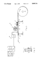
- FIG. 1 is a schematic drawing of a laser marking apparatus which includes a laser marker, a wax applicator and a wax remover for providing in an outer jacket of a moving cable the five alphanumeric characters of the word "CABLE" of enhanced readability and which has been made in accordance with the principles od the present invention.
- FIG. 2 is an end view of one of the guide rollers of the laser marking apparatus of FIG. 1.
- FIG. 3 a top plan view of a section of the outer jacket at point A after the laser marker of FIG. 1 has inscribed a plurality of dot-craters in the outer jacket opening to the outer surface thereof.
- FIG. 4 is a longitudinal side view in cross-section of the section of the cable at point A taken along line 4--4 of FIG. 3.
- FIG. 5 is a top plan view of the same section of the cable at point B after the applicator of FIG. 1 has applied wax to the outer surface of the outer jacket and the dot-craters of the same section of the cable.
- FIG. 6 is a longitudinal side view in cross-section of the same section of the cable at point B taken along line 6--6 of FIG. 5.
- FIG. 7 is a top plan view of the same section of the cable at point C after the wax remover of FIG. 1 has removed only the wax which is on the outer surface of the outer jacket leaving the wax which is in the markings and has polished the outer surface thereof so that the wax which remains in each dot-crater enhances the readability of the inscribed markings.
- FIG. 8 is a longitudinal side view in cross-section of the same section of the cable at point C taken along line 8--8 of FIG. 7.
- a laser marking apparatus 10 inscribes markings, such as alphanumeric characters and symbols, in an outer jacket 12 of a moving cable 11 which is delivered from a supply source 13.
- the cable 11 is advanced under tension and is wound onto a take-up spool 14.
- the outer jacket 12 is formed out of a high-density polyethylene material and has an outer surface.
- the outer jacket 12 is of a specified color, generally black.
- the markings are provided repetitively in sections spaced along the length of the cable 11.
- the laser marking apparatus 10 includes a first guide roller 15, a laser marker 16, an applicator 17, a coarse brush roller 18 with a first driving mechanism 19, a fine brush roller 20 with a second driving mechanism 21 and a second guide roller 22.
- the first and second guide rollers 15 and 22 are disposed adjacent to the supply source 13 before the laser marker 16 and before the take-up spool 14 after the fine brush roller 20, respectively, in order to guide the cable 11 along a path of travel so that the outer jacket 12 passes adjacent to the laser marker 16.
- the first and second driving mechanisms 19 and 21 rotatively drive the coarse brush roller 18 and the fine brush roller 20, respectively.
- the laser marker 16 inscribes in the outer jacket 12 markings opening to the outer surface thereof.
- the applicator 17 applies a flowable material, typically either white or yellow, which is different from and contrasts with the specified color of the outer jacket 12, onto the outer surface of the outer jacket 12 and into the markings along each repetitively marked section of the cable 11.
- a flowable material typically either white or yellow
- the coarse brush roller 18 removes most of the wax which is on the outer surface of the outer jacket 12 leaving the flowable material which is in the markings
- the fine brush roller 20 removes the remainder of the wax which is on the outer surface of the outer jacket 12 and polishes the outer surface thereof to enhance the readability of the markings.
- the laser marker includes a computer 23, a monitor 24 with a keyboard 25, a laser interface circuit 26, a direct current power supply 27, seven radio frequency amplifiers 28 and a laser head 29 with a beam delivery tube and a lens.
- the laser head 29 includes seven carbon dioxide lasers which are excited by radio frequency energy at a frequency of 27 megahertz to a nominal power of 20 watts.
- the output beams of the seven lasers are directed through the beam delivery tube via mirror onto the lens which focuses the output beams onto a marking area.
- the output of the seven carbon dioxide lasers are focused by the lens to form a seven dot-high vertical column of beams. Since the outer jacket 12 of the cable to be marked moves transversely with respect to the vertical column it is possible to create a 7 by n dot matrix from which alphanumeric characters and symbols may be generated by selectively controlling the beam energy of each laser.
- the keyboard 25 of the monitor 24 permits the operator to communicate with the computer 23 in order to enter data and alter the operation of the laser interface circuit 26.
- the radio frequency energy for exciting the lasers is generated by the radio frequency amplifiers 28 which are located in a control console. There is one radio frequency amplifier 28 for each laser.
- the radio frequency amplifiers 28 are controlled by digital signals from the computer 23 via the laser interface circuit 26. Each laser is separately controllable by a signal which turns the laser on or off depending on the particular character to be printed.
- the markings are a plurality of dot-craters 30 which are inscribed in the outer jacket 12 which open to the outer surface thereof.
- the dot-craters 30 are arranged in the form of an m by n matrix to generate either an alphanumeric character or a symbol.
- the depth of dot-craters 30 is in the range of 0.003 to 0.005 inches.
- the dot-craters 30 are arranged in a set of five seven by three matrices to form the five alpha characters of the word "CABLE.”
- the flowable material is a wax 31, with a pigment, typically either white or yellow.
- the applicator 17 applies the wax 31 on the outer surface of the outer jacket 12 of the same section of the cable 11.
- the wax 31 covers the outer surface of the outer jacket 12 of the same section of the cable 11 and flows into each dot-crater 30 therein.
- the applicator 17 includes a container which contains the wax 31 and which has an outlet nozzle, a heater and pressurizing mechanism.
- the container is disposed adjacent to the path of travel of the cable 11 after the laser marker 16.
- the outlet nozzle is disposed adjacent and contiguous to the outer surface of the outer jacket 12.
- the heater heats the wax 31 and is disposed in and mechanically coupled to the container.
- the pressurizing mechanism is disposed in and mechanically coupled to the container and pressurizes the heated wax 31.
- the outlet nozzle discharges the pressurized and heated wax 31 onto the outer surface of the outer jacket 12.
- the same section of the cable 11 is at point B.
- the wax 31 covers the outer surface of the outer jacket 12 of same section of the cable 11 and fills all of the dot-craters 30 therein.
- the wax 31 has a low melting point in that it melts at a temperature in the range of 80 to 100 degrees Centigrade. There is typically either a white pigment or a yellow pigment in the wax 31.
- the same section of the cable 11 is at a wax remover which includes the coarse brush roller 18 and the fine brush roller 20.
- the coarse brush roller 18 is disposed adjacent to the path of travel of the cable 11 after the applicator 17.
- the coarse brush roller 18 is adjacent and contiguous to the outer surface of the outer jacket 12.
- the first driving mechanism 19 rotatively drives the coarse brush roller 18.
- the coarse brush roller 18 removes most of the applied wax 31 which is on the outer surface of the outer jacket 12.
- the fine brush roller 20 is disposed adjacent to the path of travel of the cable 11 after the coarse brush roller 18.
- the fine brush roller 20 is disposed adjacent and contiguous to the outer surface of the outer jacket 12.
- the second driving mechanism 21 rotatively drives the fine brush roller 20.
- the fine brush roller 20 removes the remainder of the wax 31 which is on the outer surface of the outer jacket 12 and polishes the outer surface thereof so that the wax 31 which is in each dot-crater 30 remains. After the fine brush roller 20 has polished the outer surface of the outer jacket 12 so that all of the dot-craters 30 remain filled with the wax 31, the same section of the cable 11 is at point C. Each wax-filled dot-crater 30 is rendered more visible due to the contrasting colors of the outer jacket 12, which is black, and the wax 31, which is either white or yellow, so that the readability of the alphanumeric characters and symbols 32 in the outer jacket 12 of the cable 11 is enhanced.
- the laser marker 16 of the preferred embodiment includes seven carbon dioxide lasers.
- U.S. Pat. 4,636,043, entitled Laser Beam Scanning Device and Marking System, issued to Dennis R. Bellar on Jan. 13, 1987 teaches another laser marker which utilizes a laser scanner to mark items.
- U.S. Pat. No. 4,024,545, entitled Laser-Excited Marking System, issued to Terence S. Bosling, Robert J. Dompe, Harry G. Heard and Keith K. Hazard on May 17, 1977 teaches yet another laser marker for inscribing markings, such as alphanumeric characters and symbols, in the outer surface layer of an article in accordance with predetermined information.
- lasers including, but not being limited to, an argon laser, another carbon dioxide laser, a neodymium:YAG laser, an erbium:YAG laser, and an excimer laser, may be used in each of these laser marker so long as the laser marker is able to inscribe markings in the material which forms the outer jacket 12 of the cable 11.
Abstract
Description
Claims (11)
Priority Applications (1)
| Application Number | Priority Date | Filing Date | Title |
|---|---|---|---|
| US07/541,190 US5049721A (en) | 1989-09-18 | 1990-06-20 | Laser marking apparatus and method for providing markings of enhanced readability in an outer jacket of a moving cable |
Applications Claiming Priority (2)
| Application Number | Priority Date | Filing Date | Title |
|---|---|---|---|
| US40881889A | 1989-09-18 | 1989-09-18 | |
| US07/541,190 US5049721A (en) | 1989-09-18 | 1990-06-20 | Laser marking apparatus and method for providing markings of enhanced readability in an outer jacket of a moving cable |
Related Parent Applications (1)
| Application Number | Title | Priority Date | Filing Date |
|---|---|---|---|
| US40881889A Continuation | 1989-09-18 | 1989-09-18 |
Publications (1)
| Publication Number | Publication Date |
|---|---|
| US5049721A true US5049721A (en) | 1991-09-17 |
Family
ID=27020391
Family Applications (1)
| Application Number | Title | Priority Date | Filing Date |
|---|---|---|---|
| US07/541,190 Expired - Lifetime US5049721A (en) | 1989-09-18 | 1990-06-20 | Laser marking apparatus and method for providing markings of enhanced readability in an outer jacket of a moving cable |
Country Status (1)
| Country | Link |
|---|---|
| US (1) | US5049721A (en) |
Cited By (49)
| Publication number | Priority date | Publication date | Assignee | Title |
|---|---|---|---|---|
| US5247732A (en) * | 1991-04-09 | 1993-09-28 | British Aerospace Public Limited Company | Cable handling and preparation apparatus |
| US5376771A (en) * | 1992-07-07 | 1994-12-27 | Merck & Co., Inc. | High speed process for preparing orifices in pharmaceutical dosage forms |
| US5420575A (en) * | 1992-07-06 | 1995-05-30 | Motorola, Inc. | Method and apparatus for marking translucent plastics |
| US5474627A (en) * | 1990-10-11 | 1995-12-12 | Aerospatiale Societe Nationale Industrielle | Method for marking an electric cable |
| WO1996018478A1 (en) * | 1994-12-16 | 1996-06-20 | Alza Corporation | Method and apparatus for forming dispenser delivery ports |
| US5653900A (en) * | 1991-01-17 | 1997-08-05 | United Distillers Plc | Dynamic laser marking |
| US5783793A (en) * | 1996-02-29 | 1998-07-21 | Merck & Co., Inc. | Process for producing a plurality of holes in dosage forms using a laser beam deflected by an acousto-optic deflector |
| EP0883462A1 (en) * | 1996-02-29 | 1998-12-16 | Merck & Co., Inc. | Laser drilling process for producing a plurality of holes in chemical dosage forms using acousto-optic deflector |
| US6293081B1 (en) | 1997-06-12 | 2001-09-25 | Siecor Operations, Llc | Fiber optic cable marking process and a sensor device use therewith |
| US6370304B1 (en) | 1998-09-28 | 2002-04-09 | Corning Cable Systems Llc | Radiation marking of fiber optic cable components |
| US6437248B1 (en) * | 1999-03-10 | 2002-08-20 | Norddeutsche Seekabelwerke Gmbh & Co. Kg | Cable, in particular underwater cable |
| US20020134491A1 (en) * | 2000-07-24 | 2002-09-26 | Illinois Tool Works Inc. | Variable spacing strand coating method |
| US6460786B1 (en) * | 2000-06-14 | 2002-10-08 | Roberts Group Holdings Llc | Drip irrigation tape with indicia |
| US6576862B1 (en) * | 1999-01-07 | 2003-06-10 | Technolines Llc | Laser-scribing process for rubber and thermoplastic materials such as a hose |
| US20030206227A1 (en) * | 2000-04-18 | 2003-11-06 | Laserink, A California Corporation | Printing a code on a product |
| US6700094B1 (en) * | 1997-02-06 | 2004-03-02 | Compact Laser Solutions Gmbh | Device for laser writing on materials |
| US20050218125A1 (en) * | 2004-04-02 | 2005-10-06 | Addington Cary G | Laser marking |
| US20060027542A1 (en) * | 2004-04-28 | 2006-02-09 | Niraj Mahadev | Method to eliminate defects on the periphery of a slider due to conventional machining processes |
| US20060118323A1 (en) * | 2004-12-08 | 2006-06-08 | Kalisz Joseph P | Wire harness with concentric code identifier |
| US20070252663A1 (en) * | 2006-05-01 | 2007-11-01 | David Rahner | Laser Marked CATV Filter |
| US20080099312A1 (en) * | 2006-10-25 | 2008-05-01 | Habasit Ag | Modular belt with surface engraving |
| US20090095398A1 (en) * | 2007-10-11 | 2009-04-16 | Hardin William K | Method and system for applying labels to armored cable and the like |
| US20090114418A1 (en) * | 2007-11-07 | 2009-05-07 | Jl Audio, Inc. | Wire with convertible outer jacket and method thereof |
| US20090138514A1 (en) * | 2007-11-13 | 2009-05-28 | Holcombe Charles L | Traceable and Theft Deterrent Reclaimable Product |
| US20100264206A1 (en) * | 2007-11-13 | 2010-10-21 | Holcombe Charles L | Traceable and Theft Deterrent Reclaimable Product |
| US20100306983A1 (en) * | 2009-06-06 | 2010-12-09 | Robert Eugene Brooks | Method of attaching an element to a continuously moving elongated article |
| US20110011639A1 (en) * | 2009-07-16 | 2011-01-20 | Leonard Visser | Shielding tape with multiple foil layers |
| US20110011638A1 (en) * | 2009-07-16 | 2011-01-20 | Paul Gemme | Shielding tape with edge indicator |
| US7954530B1 (en) | 2009-01-30 | 2011-06-07 | Encore Wire Corporation | Method and apparatus for applying labels to cable or conduit |
| US20110220386A1 (en) * | 2007-11-13 | 2011-09-15 | Richard Temblador | Conductors and metal-covered cable with coded information and method of applying coded information |
| EP2410535A1 (en) * | 2010-07-23 | 2012-01-25 | Lapp Engineering & Co. | Cable with a tactile marking and method and device |
| RU2449771C2 (en) * | 2004-06-09 | 2012-05-10 | Смитклайн Бичам Корпорейшн | Device and method of pharmaceutical production |
| GB2492229A (en) * | 2011-06-22 | 2012-12-26 | Smartwater Ltd | Flame-temperature-resistant marker system for cables |
| WO2013104581A1 (en) * | 2012-01-12 | 2013-07-18 | Medek & Schoerner Gmbh | Device for the laser marking of elongated bodies |
| US8511596B2 (en) | 2010-10-14 | 2013-08-20 | Deere & Company | Drip tape management |
| US8579658B2 (en) | 2010-08-20 | 2013-11-12 | Timothy L. Youtsey | Coaxial cable connectors with washers for preventing separation of mated connectors |
| US8830519B1 (en) * | 2011-06-17 | 2014-09-09 | Encore Wire Corporation | System, apparatus, and method for effectively applying proper sequential alpha-numerics to extruded wire and cable |
| US8826960B1 (en) | 2009-06-15 | 2014-09-09 | Encore Wire Corporation | System and apparatus for applying labels to cable or conduit |
| US8882520B2 (en) | 2010-05-21 | 2014-11-11 | Pct International, Inc. | Connector with a locking mechanism and a movable collet |
| US9028276B2 (en) | 2011-12-06 | 2015-05-12 | Pct International, Inc. | Coaxial cable continuity device |
| US9053841B2 (en) | 2007-11-13 | 2015-06-09 | Southwire Company, Llc | Traceable and theft deterrent reclaimable product |
| CN104992792A (en) * | 2015-07-07 | 2015-10-21 | 江苏亨通电力电缆有限公司 | Surface printing device for coal mine cabtyre cables |
| US9409668B1 (en) | 2007-06-04 | 2016-08-09 | Encore Wire Corporation | Method and apparatus for applying labels to cable |
| CN106347003A (en) * | 2016-11-15 | 2017-01-25 | 苏州亨达尔工业材料有限公司 | Engraving machine with dust removal device |
| US10102461B2 (en) | 2007-11-13 | 2018-10-16 | Southwire Company, Llc | Traceable and theft deterrent reclaimable product |
| CN110508931A (en) * | 2019-08-30 | 2019-11-29 | 国网山东省电力公司平阴县供电公司 | A kind of portable cable marking device |
| US10583668B2 (en) | 2018-08-07 | 2020-03-10 | Markem-Imaje Corporation | Symbol grouping and striping for wide field matrix laser marking |
| US11031157B1 (en) | 2013-08-23 | 2021-06-08 | Southwire Company, Llc | System and method of printing indicia onto armored cable |
| US11319104B1 (en) | 2009-01-30 | 2022-05-03 | Encore Wire Corporation | System and apparatus for applying labels to cable or conduit |
Citations (12)
| Publication number | Priority date | Publication date | Assignee | Title |
|---|---|---|---|---|
| US1607432A (en) * | 1924-10-18 | 1926-11-16 | Callenders Cable & Const Co | Electric cable |
| US2745436A (en) * | 1950-10-03 | 1956-05-15 | Douglas Aircraft Co Inc | Solvent proof marking for conduits |
| US2867001A (en) * | 1954-12-03 | 1959-01-06 | Western Insulated Wire Co | Means and method for forming indicia on the surface of continuous vulcanized products |
| US3076235A (en) * | 1960-03-09 | 1963-02-05 | Superior Cable Corp | Method for striping conductor coatings |
| GB980221A (en) * | 1961-08-05 | 1965-01-13 | Wednesbury Tube Company Ltd | Improvements relating to electric cables |
| US3229623A (en) * | 1964-06-15 | 1966-01-18 | Gen Cable Corp | Marking metal sheathed cables |
| DE2260109A1 (en) * | 1971-12-10 | 1973-06-28 | Peugeot | SELF-SUPPORTING AND TWIST-FREE FLAT CABLE |
| DE2261696A1 (en) * | 1971-12-23 | 1973-06-28 | Texaco Development Corp | PROCESS FOR THE OBTAINING A NITROGEN-CONTAINING DISPERSANT FOR LUBRICATING OIL |
| US4028523A (en) * | 1974-12-10 | 1977-06-07 | Steigerwald Strahltechnik Gmbh | Energy-beam engraving method and an apparatus for carrying it out |
| US4370542A (en) * | 1980-05-22 | 1983-01-25 | Westland Aircraft Limited | Cable marking method and apparatus |
| US4816374A (en) * | 1985-04-12 | 1989-03-28 | Societe D'applications Plastiques Rhone-Alpes (Sapra) | Method of making a plastic material sensitive to laser radiation and enabling it to be marked by a laser, and articles obtained thereby |
| US4854147A (en) * | 1986-03-24 | 1989-08-08 | The Boeing Company | Wire pinch mark applicator |
-
1990
- 1990-06-20 US US07/541,190 patent/US5049721A/en not_active Expired - Lifetime
Patent Citations (13)
| Publication number | Priority date | Publication date | Assignee | Title |
|---|---|---|---|---|
| US1607432A (en) * | 1924-10-18 | 1926-11-16 | Callenders Cable & Const Co | Electric cable |
| US2745436A (en) * | 1950-10-03 | 1956-05-15 | Douglas Aircraft Co Inc | Solvent proof marking for conduits |
| US2867001A (en) * | 1954-12-03 | 1959-01-06 | Western Insulated Wire Co | Means and method for forming indicia on the surface of continuous vulcanized products |
| US3076235A (en) * | 1960-03-09 | 1963-02-05 | Superior Cable Corp | Method for striping conductor coatings |
| GB980221A (en) * | 1961-08-05 | 1965-01-13 | Wednesbury Tube Company Ltd | Improvements relating to electric cables |
| US3193614A (en) * | 1961-08-05 | 1965-07-06 | Wednesbury Tube Company Ltd | Electric cables |
| US3229623A (en) * | 1964-06-15 | 1966-01-18 | Gen Cable Corp | Marking metal sheathed cables |
| DE2260109A1 (en) * | 1971-12-10 | 1973-06-28 | Peugeot | SELF-SUPPORTING AND TWIST-FREE FLAT CABLE |
| DE2261696A1 (en) * | 1971-12-23 | 1973-06-28 | Texaco Development Corp | PROCESS FOR THE OBTAINING A NITROGEN-CONTAINING DISPERSANT FOR LUBRICATING OIL |
| US4028523A (en) * | 1974-12-10 | 1977-06-07 | Steigerwald Strahltechnik Gmbh | Energy-beam engraving method and an apparatus for carrying it out |
| US4370542A (en) * | 1980-05-22 | 1983-01-25 | Westland Aircraft Limited | Cable marking method and apparatus |
| US4816374A (en) * | 1985-04-12 | 1989-03-28 | Societe D'applications Plastiques Rhone-Alpes (Sapra) | Method of making a plastic material sensitive to laser radiation and enabling it to be marked by a laser, and articles obtained thereby |
| US4854147A (en) * | 1986-03-24 | 1989-08-08 | The Boeing Company | Wire pinch mark applicator |
Cited By (89)
| Publication number | Priority date | Publication date | Assignee | Title |
|---|---|---|---|---|
| US5827391A (en) * | 1990-10-11 | 1998-10-27 | Aerospatiale Societe Nationale Industrielle | Machine for marking an electric cable |
| US5474627A (en) * | 1990-10-11 | 1995-12-12 | Aerospatiale Societe Nationale Industrielle | Method for marking an electric cable |
| US5653900A (en) * | 1991-01-17 | 1997-08-05 | United Distillers Plc | Dynamic laser marking |
| US5247732A (en) * | 1991-04-09 | 1993-09-28 | British Aerospace Public Limited Company | Cable handling and preparation apparatus |
| US5420575A (en) * | 1992-07-06 | 1995-05-30 | Motorola, Inc. | Method and apparatus for marking translucent plastics |
| US5376771A (en) * | 1992-07-07 | 1994-12-27 | Merck & Co., Inc. | High speed process for preparing orifices in pharmaceutical dosage forms |
| WO1996018478A1 (en) * | 1994-12-16 | 1996-06-20 | Alza Corporation | Method and apparatus for forming dispenser delivery ports |
| US5658474A (en) * | 1994-12-16 | 1997-08-19 | Alza Corporation | Method and apparatus for forming dispenser delivery ports |
| US5698119A (en) * | 1994-12-16 | 1997-12-16 | Alza Corporation | Apparatus for forming dispenser delivery ports |
| US5783793A (en) * | 1996-02-29 | 1998-07-21 | Merck & Co., Inc. | Process for producing a plurality of holes in dosage forms using a laser beam deflected by an acousto-optic deflector |
| EP0883462A1 (en) * | 1996-02-29 | 1998-12-16 | Merck & Co., Inc. | Laser drilling process for producing a plurality of holes in chemical dosage forms using acousto-optic deflector |
| EP0883462A4 (en) * | 1996-02-29 | 2003-04-09 | Merck & Co Inc | Laser drilling process for producing a plurality of holes in chemical dosage forms using acousto-optic deflector |
| US6700094B1 (en) * | 1997-02-06 | 2004-03-02 | Compact Laser Solutions Gmbh | Device for laser writing on materials |
| US6293081B1 (en) | 1997-06-12 | 2001-09-25 | Siecor Operations, Llc | Fiber optic cable marking process and a sensor device use therewith |
| US6370304B1 (en) | 1998-09-28 | 2002-04-09 | Corning Cable Systems Llc | Radiation marking of fiber optic cable components |
| US6576862B1 (en) * | 1999-01-07 | 2003-06-10 | Technolines Llc | Laser-scribing process for rubber and thermoplastic materials such as a hose |
| US6437248B1 (en) * | 1999-03-10 | 2002-08-20 | Norddeutsche Seekabelwerke Gmbh & Co. Kg | Cable, in particular underwater cable |
| US6829000B2 (en) | 2000-04-18 | 2004-12-07 | Laserink | Printing a code on a product |
| US20030206227A1 (en) * | 2000-04-18 | 2003-11-06 | Laserink, A California Corporation | Printing a code on a product |
| US20040141052A1 (en) * | 2000-04-18 | 2004-07-22 | Laserink, A California Corporation | Printing a code on a product |
| US6791592B2 (en) | 2000-04-18 | 2004-09-14 | Laserink | Printing a code on a product |
| US6460786B1 (en) * | 2000-06-14 | 2002-10-08 | Roberts Group Holdings Llc | Drip irrigation tape with indicia |
| US20020134491A1 (en) * | 2000-07-24 | 2002-09-26 | Illinois Tool Works Inc. | Variable spacing strand coating method |
| US6875296B2 (en) * | 2000-07-24 | 2005-04-05 | Illinois Tool Works Inc. | Variable spacing strand coating method |
| US20050218125A1 (en) * | 2004-04-02 | 2005-10-06 | Addington Cary G | Laser marking |
| US20060027542A1 (en) * | 2004-04-28 | 2006-02-09 | Niraj Mahadev | Method to eliminate defects on the periphery of a slider due to conventional machining processes |
| RU2449771C2 (en) * | 2004-06-09 | 2012-05-10 | Смитклайн Бичам Корпорейшн | Device and method of pharmaceutical production |
| US20060118323A1 (en) * | 2004-12-08 | 2006-06-08 | Kalisz Joseph P | Wire harness with concentric code identifier |
| US20110197250A1 (en) * | 2006-05-01 | 2011-08-11 | John Mezzalingua Associates, Inc. | Laser Marked CATV Filter |
| US20070252663A1 (en) * | 2006-05-01 | 2007-11-01 | David Rahner | Laser Marked CATV Filter |
| US8124910B2 (en) | 2006-05-01 | 2012-02-28 | John Mezzalingua Associates, Inc. | Laser marked CATV filter |
| US20080099312A1 (en) * | 2006-10-25 | 2008-05-01 | Habasit Ag | Modular belt with surface engraving |
| US11827409B1 (en) | 2007-06-04 | 2023-11-28 | Encore Wire Corporation | Method and apparatus for applying labels to cable |
| US9452856B1 (en) | 2007-06-04 | 2016-09-27 | Encore Wire Corporation | Method and apparatus for applying labels to cable |
| US11247404B1 (en) | 2007-06-04 | 2022-02-15 | Encore Wire Corporation | Method and apparatus for applying labels to cable |
| US10759558B1 (en) | 2007-06-04 | 2020-09-01 | Encore Wire Corporation | Method and apparatus for applying labels to cable |
| US10272616B1 (en) | 2007-06-04 | 2019-04-30 | Encore Wire Corporation | Method and apparatus for applying labels to cable |
| US11667085B1 (en) | 2007-06-04 | 2023-06-06 | Encore Wire Corporation | Method and apparatus for applying labels to cable |
| US10046879B1 (en) | 2007-06-04 | 2018-08-14 | Encore Wire Corporation | Method and apparatus for applying labels to cable |
| US9409668B1 (en) | 2007-06-04 | 2016-08-09 | Encore Wire Corporation | Method and apparatus for applying labels to cable |
| US11498715B1 (en) | 2007-06-04 | 2022-11-15 | Encore Wire Corporation | Method and apparatus for applying labels to cable |
| US20090095398A1 (en) * | 2007-10-11 | 2009-04-16 | Hardin William K | Method and system for applying labels to armored cable and the like |
| US8540836B1 (en) | 2007-10-11 | 2013-09-24 | Southwire Corporation | Method for applying coded labels to cable |
| US8347533B2 (en) | 2007-10-11 | 2013-01-08 | Southwire Company | Machine applied labels to armored cable |
| US9070308B2 (en) | 2007-10-11 | 2015-06-30 | Southwire Company, Llc | Labeled armored electrical cable |
| US20090114418A1 (en) * | 2007-11-07 | 2009-05-07 | Jl Audio, Inc. | Wire with convertible outer jacket and method thereof |
| US9887023B2 (en) | 2007-11-13 | 2018-02-06 | Southwire Company, Llc | Traceable and theft deterrent reclaimable product |
| US9053841B2 (en) | 2007-11-13 | 2015-06-09 | Southwire Company, Llc | Traceable and theft deterrent reclaimable product |
| US10102461B2 (en) | 2007-11-13 | 2018-10-16 | Southwire Company, Llc | Traceable and theft deterrent reclaimable product |
| US20090138514A1 (en) * | 2007-11-13 | 2009-05-28 | Holcombe Charles L | Traceable and Theft Deterrent Reclaimable Product |
| US20110220386A1 (en) * | 2007-11-13 | 2011-09-15 | Richard Temblador | Conductors and metal-covered cable with coded information and method of applying coded information |
| US9818508B2 (en) | 2007-11-13 | 2017-11-14 | Southwire Company, Llc | Traceable and theft deterrent reclaimable product |
| US8234304B2 (en) | 2007-11-13 | 2012-07-31 | Southwire Company | Traceable and theft deterrent reclaimable product |
| US20100264206A1 (en) * | 2007-11-13 | 2010-10-21 | Holcombe Charles L | Traceable and Theft Deterrent Reclaimable Product |
| US9040825B2 (en) * | 2007-11-13 | 2015-05-26 | Southwire Company, Llc | Conductors and metal-covered cable with coded information and method of applying coded information |
| US9321548B1 (en) | 2009-01-30 | 2016-04-26 | Encore Wire Corporation | Method for applying labels to cable or conduit |
| US9950826B1 (en) | 2009-01-30 | 2018-04-24 | Encore Wire Corporation | Method for applying labels to cable or conduit |
| US7954530B1 (en) | 2009-01-30 | 2011-06-07 | Encore Wire Corporation | Method and apparatus for applying labels to cable or conduit |
| US11319104B1 (en) | 2009-01-30 | 2022-05-03 | Encore Wire Corporation | System and apparatus for applying labels to cable or conduit |
| US10654607B1 (en) | 2009-01-30 | 2020-05-19 | Encore Wire Corporation | System and apparatus for applying labels to cable or conduit |
| US11851233B1 (en) | 2009-01-30 | 2023-12-26 | Encore Wire Corporation | System and apparatus for applying labels to cable or conduit |
| US9446877B1 (en) | 2009-01-30 | 2016-09-20 | Encore Wire Corporation | System and apparatus for applying labels to cable or conduit |
| US11673702B1 (en) | 2009-01-30 | 2023-06-13 | Encore Wire Corporation | Method for applying labels to cable or conduit |
| US10035618B1 (en) | 2009-01-30 | 2018-07-31 | Encore Wire Corporation | System and apparatus for applying labels to cable or conduit |
| US10906685B1 (en) | 2009-01-30 | 2021-02-02 | Encore Wire Corporation | Method for applying labels to cable or conduit |
| US8454785B1 (en) | 2009-01-30 | 2013-06-04 | Encore Wire Corporation | Method for applying labels to cable or conduit |
| US20100306983A1 (en) * | 2009-06-06 | 2010-12-09 | Robert Eugene Brooks | Method of attaching an element to a continuously moving elongated article |
| US8826960B1 (en) | 2009-06-15 | 2014-09-09 | Encore Wire Corporation | System and apparatus for applying labels to cable or conduit |
| US20110011638A1 (en) * | 2009-07-16 | 2011-01-20 | Paul Gemme | Shielding tape with edge indicator |
| US9728304B2 (en) | 2009-07-16 | 2017-08-08 | Pct International, Inc. | Shielding tape with multiple foil layers |
| US11037703B2 (en) | 2009-07-16 | 2021-06-15 | Pct International, Inc. | Shielding tape with multiple foil layers |
| US20110011639A1 (en) * | 2009-07-16 | 2011-01-20 | Leonard Visser | Shielding tape with multiple foil layers |
| US10424423B2 (en) | 2009-07-16 | 2019-09-24 | Pct International, Inc. | Shielding tape with multiple foil layers |
| US8882520B2 (en) | 2010-05-21 | 2014-11-11 | Pct International, Inc. | Connector with a locking mechanism and a movable collet |
| EP2410535A1 (en) * | 2010-07-23 | 2012-01-25 | Lapp Engineering & Co. | Cable with a tactile marking and method and device |
| US8579658B2 (en) | 2010-08-20 | 2013-11-12 | Timothy L. Youtsey | Coaxial cable connectors with washers for preventing separation of mated connectors |
| US8511596B2 (en) | 2010-10-14 | 2013-08-20 | Deere & Company | Drip tape management |
| US8830519B1 (en) * | 2011-06-17 | 2014-09-09 | Encore Wire Corporation | System, apparatus, and method for effectively applying proper sequential alpha-numerics to extruded wire and cable |
| US9305683B1 (en) | 2011-06-17 | 2016-04-05 | Encore Wire Corporation | System, apparatus, and method for effectively applying proper sequential alpha-numerics to extruded wire and cable |
| GB2492229A (en) * | 2011-06-22 | 2012-12-26 | Smartwater Ltd | Flame-temperature-resistant marker system for cables |
| US9028276B2 (en) | 2011-12-06 | 2015-05-12 | Pct International, Inc. | Coaxial cable continuity device |
| WO2013104581A1 (en) * | 2012-01-12 | 2013-07-18 | Medek & Schoerner Gmbh | Device for the laser marking of elongated bodies |
| US11031157B1 (en) | 2013-08-23 | 2021-06-08 | Southwire Company, Llc | System and method of printing indicia onto armored cable |
| US11670438B2 (en) | 2013-08-23 | 2023-06-06 | Southwire Company, Llc | System and method of printing indicia onto armored cable |
| CN106128654A (en) * | 2015-07-07 | 2016-11-16 | 江苏亨通电力电缆有限公司 | Printing device for cable cover(ing) surface |
| CN104992792A (en) * | 2015-07-07 | 2015-10-21 | 江苏亨通电力电缆有限公司 | Surface printing device for coal mine cabtyre cables |
| CN106347003A (en) * | 2016-11-15 | 2017-01-25 | 苏州亨达尔工业材料有限公司 | Engraving machine with dust removal device |
| US10583668B2 (en) | 2018-08-07 | 2020-03-10 | Markem-Imaje Corporation | Symbol grouping and striping for wide field matrix laser marking |
| CN110508931A (en) * | 2019-08-30 | 2019-11-29 | 国网山东省电力公司平阴县供电公司 | A kind of portable cable marking device |
Similar Documents
| Publication | Publication Date | Title |
|---|---|---|
| US5049721A (en) | Laser marking apparatus and method for providing markings of enhanced readability in an outer jacket of a moving cable | |
| EP0415674B1 (en) | Article having marking thereon and methods of making | |
| KR100289829B1 (en) | How to install labels on rubber products | |
| US4307047A (en) | Method of manufacture of identical parts displaying different indicia | |
| EP0854761B1 (en) | Co2 laser marking of coated surfaces for product identification | |
| DE69831469T2 (en) | Identification of a printer cartridge | |
| WO2006114600A2 (en) | Multi-colour printing | |
| US20050269033A1 (en) | Thermal activation method and thermal activation device for a heat-sensitive adhesive sheet | |
| DE69913206T2 (en) | METHOD FOR THERMAL MASS TRANSFER PRESSURE | |
| JP2001080025A (en) | Method and apparatus for forming reversible image line part on printing plate | |
| US4609926A (en) | Ribbon transfer color-on-demand resistive ribbon printing | |
| GB2269782A (en) | Method and apparatus for marking information on the outer surface of a polymer covered cable or wire. | |
| JP3641248B2 (en) | Manufacturing method of wire instruction mark | |
| US4577983A (en) | Color-on-demand ribbon printing | |
| EP0146069A2 (en) | Apparatus and method for thermal transfer printing | |
| KR101959276B1 (en) | Method for forming color decoration by using laser printing | |
| AU767732B2 (en) | High contrast surface marking | |
| JP2001129772A (en) | Marking method onto polyvinyl chloride product | |
| EP0159444A2 (en) | Method of and apparatus for printing colored patterns by the use of variegated, heat-sensitive ink ribbon | |
| JPH06198463A (en) | Marking method to thermoplastic resin | |
| JPH06198462A (en) | Marking method to thermosetting resin | |
| AU6555201A (en) | High contrast surface marking | |
| JPH0790657B2 (en) | Thermal transfer printer | |
| JPH03284986A (en) | Gradation expressing method and gradation expressed printed matter | |
| AU6555401A (en) | High contrast surface marking |
Legal Events
| Date | Code | Title | Description |
|---|---|---|---|
| STCF | Information on status: patent grant |
Free format text: PATENTED CASE |
|
| FEPP | Fee payment procedure |
Free format text: PAYOR NUMBER ASSIGNED (ORIGINAL EVENT CODE: ASPN); ENTITY STATUS OF PATENT OWNER: LARGE ENTITY |
|
| FPAY | Fee payment |
Year of fee payment: 4 |
|
| FEPP | Fee payment procedure |
Free format text: PAYER NUMBER DE-ASSIGNED (ORIGINAL EVENT CODE: RMPN); ENTITY STATUS OF PATENT OWNER: LARGE ENTITY Free format text: PAYOR NUMBER ASSIGNED (ORIGINAL EVENT CODE: ASPN); ENTITY STATUS OF PATENT OWNER: LARGE ENTITY |
|
| FPAY | Fee payment |
Year of fee payment: 8 |
|
| AS | Assignment |
Owner name: LUCENT TECHNOLOGIES, INC., NEW JERSEY Free format text: ASSIGNMENT OF ASSIGNORS INTEREST;ASSIGNOR:AT&T CORP.;REEL/FRAME:012754/0365 Effective date: 19960329 Owner name: AVAYA TECHNOLOGY CORP., NEW JERSEY Free format text: ASSIGNMENT OF ASSIGNORS INTEREST;ASSIGNOR:LUCENT TECHNOLOGIES INC.;REEL/FRAME:012754/0770 Effective date: 20000929 |
|
| AS | Assignment |
Owner name: BANK OF NEW YORK, THE, NEW YORK Free format text: SECURITY INTEREST;ASSIGNOR:AVAYA TECHNOLOGY CORP.;REEL/FRAME:012762/0160 Effective date: 20020405 |
|
| REMI | Maintenance fee reminder mailed | ||
| FPAY | Fee payment |
Year of fee payment: 12 |
|
| SULP | Surcharge for late payment |
Year of fee payment: 11 |
|
| AS | Assignment |
Owner name: AVAYA TECHNOLOGY CORPORATION, NEW JERSEY Free format text: RELEASE BY SECURED PARTY;ASSIGNOR:THE BANK OF NEW YORK;REEL/FRAME:019881/0532 Effective date: 20040101 |
|
| AS | Assignment |
Owner name: COMMSCOPE SOLUTIONS PROPERTIES, LLC, NEVADA Free format text: ASSIGNMENT OF ASSIGNORS INTEREST;ASSIGNOR:AVAYA TECHNOLOGY CORPORATION;REEL/FRAME:019984/0001 Effective date: 20040129 |
|
| AS | Assignment |
Owner name: COMMSCOPE, INC. OF NORTH CAROLINA, NORTH CAROLINA Free format text: MERGER;ASSIGNOR:COMMSCOPE SOLUTIONS PROPERTIES, LLC;REEL/FRAME:019991/0643 Effective date: 20061220 Owner name: COMMSCOPE, INC. OF NORTH CAROLINA,NORTH CAROLINA Free format text: MERGER;ASSIGNOR:COMMSCOPE SOLUTIONS PROPERTIES, LLC;REEL/FRAME:019991/0643 Effective date: 20061220 |
|
| AS | Assignment |
Owner name: BANK OF AMERICA, N.A., AS ADMINISTRATIVE AGENT, CA Free format text: SECURITY AGREEMENT;ASSIGNORS:COMMSCOPE, INC. OF NORTH CAROLINA;ALLEN TELECOM, LLC;ANDREW CORPORATION;REEL/FRAME:020362/0241 Effective date: 20071227 Owner name: BANK OF AMERICA, N.A., AS ADMINISTRATIVE AGENT,CAL Free format text: SECURITY AGREEMENT;ASSIGNORS:COMMSCOPE, INC. OF NORTH CAROLINA;ALLEN TELECOM, LLC;ANDREW CORPORATION;REEL/FRAME:020362/0241 Effective date: 20071227 |
|
| AS | Assignment |
Owner name: COMMSCOPE, INC. OF NORTH CAROLINA, NORTH CAROLINA Free format text: PATENT RELEASE;ASSIGNOR:BANK OF AMERICA, N.A., AS ADMINISTRATIVE AGENT;REEL/FRAME:026039/0005 Effective date: 20110114 Owner name: ALLEN TELECOM LLC, NORTH CAROLINA Free format text: PATENT RELEASE;ASSIGNOR:BANK OF AMERICA, N.A., AS ADMINISTRATIVE AGENT;REEL/FRAME:026039/0005 Effective date: 20110114 Owner name: ANDREW LLC (F/K/A ANDREW CORPORATION), NORTH CAROL Free format text: PATENT RELEASE;ASSIGNOR:BANK OF AMERICA, N.A., AS ADMINISTRATIVE AGENT;REEL/FRAME:026039/0005 Effective date: 20110114 |