US5052565A - Device for fastening a C-shaped mounting rail to a wall provided with screw holes - Google Patents
Device for fastening a C-shaped mounting rail to a wall provided with screw holes Download PDFInfo
- Publication number
- US5052565A US5052565A US07/579,623 US57962390A US5052565A US 5052565 A US5052565 A US 5052565A US 57962390 A US57962390 A US 57962390A US 5052565 A US5052565 A US 5052565A
- Authority
- US
- United States
- Prior art keywords
- fastening
- wall
- accordance
- mounting rail
- fastening block
- Prior art date
- Legal status (The legal status is an assumption and is not a legal conclusion. Google has not performed a legal analysis and makes no representation as to the accuracy of the status listed.)
- Expired - Lifetime
Links
- 238000002347 injection Methods 0.000 description 1
- 239000007924 injection Substances 0.000 description 1
- 230000037431 insertion Effects 0.000 description 1
- 238000003780 insertion Methods 0.000 description 1
- 239000002184 metal Substances 0.000 description 1
- 238000010079 rubber tapping Methods 0.000 description 1
Images
Classifications
-
- F—MECHANICAL ENGINEERING; LIGHTING; HEATING; WEAPONS; BLASTING
- F16—ENGINEERING ELEMENTS AND UNITS; GENERAL MEASURES FOR PRODUCING AND MAINTAINING EFFECTIVE FUNCTIONING OF MACHINES OR INSTALLATIONS; THERMAL INSULATION IN GENERAL
- F16B—DEVICES FOR FASTENING OR SECURING CONSTRUCTIONAL ELEMENTS OR MACHINE PARTS TOGETHER, e.g. NAILS, BOLTS, CIRCLIPS, CLAMPS, CLIPS OR WEDGES; JOINTS OR JOINTING
- F16B7/00—Connections of rods or tubes, e.g. of non-circular section, mutually, including resilient connections
- F16B7/22—Connections of rods or tubes, e.g. of non-circular section, mutually, including resilient connections using hooks or like elements
-
- A—HUMAN NECESSITIES
- A47—FURNITURE; DOMESTIC ARTICLES OR APPLIANCES; COFFEE MILLS; SPICE MILLS; SUCTION CLEANERS IN GENERAL
- A47B—TABLES; DESKS; OFFICE FURNITURE; CABINETS; DRAWERS; GENERAL DETAILS OF FURNITURE
- A47B57/00—Cabinets, racks or shelf units, characterised by features for adjusting shelves or partitions
- A47B57/30—Cabinets, racks or shelf units, characterised by features for adjusting shelves or partitions with means for adjusting the height of detachable shelf supports
- A47B57/36—Cabinets, racks or shelf units, characterised by features for adjusting shelves or partitions with means for adjusting the height of detachable shelf supports consisting of side walls of the ladder type
- A47B57/38—Cabinets, racks or shelf units, characterised by features for adjusting shelves or partitions with means for adjusting the height of detachable shelf supports consisting of side walls of the ladder type with hooks on the shelf supports to engage the rungs of the ladder
-
- F—MECHANICAL ENGINEERING; LIGHTING; HEATING; WEAPONS; BLASTING
- F16—ENGINEERING ELEMENTS AND UNITS; GENERAL MEASURES FOR PRODUCING AND MAINTAINING EFFECTIVE FUNCTIONING OF MACHINES OR INSTALLATIONS; THERMAL INSULATION IN GENERAL
- F16B—DEVICES FOR FASTENING OR SECURING CONSTRUCTIONAL ELEMENTS OR MACHINE PARTS TOGETHER, e.g. NAILS, BOLTS, CIRCLIPS, CLAMPS, CLIPS OR WEDGES; JOINTS OR JOINTING
- F16B7/00—Connections of rods or tubes, e.g. of non-circular section, mutually, including resilient connections
- F16B7/04—Clamping or clipping connections
- F16B7/044—Clamping or clipping connections for rods or tubes being in angled relationship
- F16B7/0446—Clamping or clipping connections for rods or tubes being in angled relationship for tubes using the innerside thereof
- F16B7/0453—Clamping or clipping connections for rods or tubes being in angled relationship for tubes using the innerside thereof the tubes being drawn towards each other
-
- F—MECHANICAL ENGINEERING; LIGHTING; HEATING; WEAPONS; BLASTING
- F16—ENGINEERING ELEMENTS AND UNITS; GENERAL MEASURES FOR PRODUCING AND MAINTAINING EFFECTIVE FUNCTIONING OF MACHINES OR INSTALLATIONS; THERMAL INSULATION IN GENERAL
- F16B—DEVICES FOR FASTENING OR SECURING CONSTRUCTIONAL ELEMENTS OR MACHINE PARTS TOGETHER, e.g. NAILS, BOLTS, CIRCLIPS, CLAMPS, CLIPS OR WEDGES; JOINTS OR JOINTING
- F16B7/00—Connections of rods or tubes, e.g. of non-circular section, mutually, including resilient connections
- F16B7/18—Connections of rods or tubes, e.g. of non-circular section, mutually, including resilient connections using screw-thread elements
-
- H—ELECTRICITY
- H02—GENERATION; CONVERSION OR DISTRIBUTION OF ELECTRIC POWER
- H02B—BOARDS, SUBSTATIONS OR SWITCHING ARRANGEMENTS FOR THE SUPPLY OR DISTRIBUTION OF ELECTRIC POWER
- H02B1/00—Frameworks, boards, panels, desks, casings; Details of substations or switching arrangements
- H02B1/01—Frameworks
-
- H—ELECTRICITY
- H05—ELECTRIC TECHNIQUES NOT OTHERWISE PROVIDED FOR
- H05K—PRINTED CIRCUITS; CASINGS OR CONSTRUCTIONAL DETAILS OF ELECTRIC APPARATUS; MANUFACTURE OF ASSEMBLAGES OF ELECTRICAL COMPONENTS
- H05K7/00—Constructional details common to different types of electric apparatus
- H05K7/18—Construction of rack or frame
- H05K7/183—Construction of rack or frame support rails therefor
-
- F—MECHANICAL ENGINEERING; LIGHTING; HEATING; WEAPONS; BLASTING
- F16—ENGINEERING ELEMENTS AND UNITS; GENERAL MEASURES FOR PRODUCING AND MAINTAINING EFFECTIVE FUNCTIONING OF MACHINES OR INSTALLATIONS; THERMAL INSULATION IN GENERAL
- F16B—DEVICES FOR FASTENING OR SECURING CONSTRUCTIONAL ELEMENTS OR MACHINE PARTS TOGETHER, e.g. NAILS, BOLTS, CIRCLIPS, CLAMPS, CLIPS OR WEDGES; JOINTS OR JOINTING
- F16B2200/00—Constructional details of connections not covered for in other groups of this subclass
- F16B2200/20—Connections with hook-like parts gripping behind a blind side of an element to be connected
- F16B2200/205—Connections with hook-like parts gripping behind a blind side of an element to be connected the hook being a separate retainer
-
- Y—GENERAL TAGGING OF NEW TECHNOLOGICAL DEVELOPMENTS; GENERAL TAGGING OF CROSS-SECTIONAL TECHNOLOGIES SPANNING OVER SEVERAL SECTIONS OF THE IPC; TECHNICAL SUBJECTS COVERED BY FORMER USPC CROSS-REFERENCE ART COLLECTIONS [XRACs] AND DIGESTS
- Y10—TECHNICAL SUBJECTS COVERED BY FORMER USPC
- Y10T—TECHNICAL SUBJECTS COVERED BY FORMER US CLASSIFICATION
- Y10T403/00—Joints and connections
- Y10T403/55—Member ends joined by inserted section
- Y10T403/557—Expansible section
Definitions
- the invention relates to a device for fastening the end of a C-shaped mounting rail to a wall with holes of a control cabinet or to a wall with holes of a frame piece of a control cabinet frame.
- the device has a fastening block which can be inserted into the end of the rail, which is adapted to the inside cross section of the mounting rail and which can be fastened to the wall by means of a fastening screw.
- a similar device is known from German Utility Model DE-GM 88 05 118.
- the fastening block is provided with a stop plate limiting the insertion movement of the fastening block in the inner receptacle of the mounting rail.
- the side of the stop plate facing the wall includes the fastening screw hole for the fastening screw, which is inserted into the screw hole in the wall from the backside of the wall and screwed into the fastening screw hole of the fastening block.
- An example would be the fastening of a mounting rail to a frame of a control cabinet, where the screw holes are provided in a wall of the frame which essentially is composed of rectangular profile sections which are not accessible from the interior of the rectangular profile sections.
- the object of the invention is to provide a device of the type mentioned above, where the fastening of the end of a mounting rail to a wall with screw holes is easily done when this wall is only accessible from the fastening side.
- the wall has a row of rectangular or square cutouts and, placed between them and offset by one-half spacing, a row of screw holes.
- the fastening block is closed off with a fastening plate on the side facing the wall.
- the fastening plate has an L-shaped hanger on the side facing the wall, which is adapted to the cutouts and the thickness of the wall and can be hung in a cutout.
- the fastening plate has a screw hole for receiving a fastening tap screw outside of the fastening block, which can be screwed into a screw hole in the wall when the fastening plate has been hung.
- the fastening block can first be hung from the fastening side in a cutout of the wall by means of the hanger of the fastening plate. Then the fastening plate is screwed with the fastening screw into the appropriately offset screw hole of the wall. In this case the fastening screw must be self-tapping in order to be sufficiently well seated in the screw hole.
- the fastening block has a U-shaped recess which defines a square nut with a threaded bore on three sides, and where the threaded bore is directed crosswise to the longitudinal axis of the mounting rail and vertically to the base leg of the same and receives a tensioning screw for the axial seating of the fastening block in the mounting rail, it is possible to fasten the mounting rail without axial play between two walls.
- This has the additional advantage that the mounting rail, which is cut into sections, does not need to be exactly adapted to the distance between the two walls.
- the legs of the L-shaped fastener have a width adapted to the associated size of the cutouts. Hanging, together with screw fastening, results in fixing the mounting rail so it cannot twist.
- the device can be designed and made in a simple way in that the fastening plate with the hanger is made of one piece with the fastening block.
- the fastening block with the square nut and the fastening plate be formed as a metal-cast component, in particular an injection die-cast metal component.
- Handling of the device is made easier by rounding of the corners of the fastening plate.
- the weight of the fastening block can be reduced to a minimum by using a U-shaped cutout leaving the fastening block open, so that only two pieces of its frame remain, supporting the square nut.
- Variations in the dimensions of the interior cross section of the mounting rail can be compensated for the most part by providing the outsides of the fastening block frame pieces with crosswise directed grooves, fins, or the like.
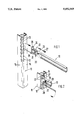
- FIG. 1 is an exploded view of the parts for fastening the end of a C-shaped mounting rail on a piece of the frame of a control cabinet, and
- FIG. 2 shows the completed connection with the axial fixing of the mounting rail.
- FIG. 1 Only a section of the C-shaped mounting rail 10 is shown in FIG. 1, the left end of which is intended to be fastened to the piece of a frame of a control cabinet.
- the right end of the mounting rail 10 may be fastened in the same way to another piece of the same frame disposed at a distance.
- the device has a cuboid fastening block 20 adapted to the interior cross section of the mounting rail 10, which can be inserted into the interior of the mounting rail 10 until the fastening plate 24 abuts the end of the rail.
- the U-shaped recess 21 defines the square nut 22, into which the threaded bore 23 has been cut, in the fastening block 20.
- This threaded bore 23 extends crosswise to the longitudinal axis of the mounting rail 10 and vertically to the base leg of the mounting rail.
- the fastening plate 24 extends on at least one short side beyond the mounting rail 10 and has in this area the screw hole 26 for the fastening screw 27.
- the long sides of the fastening plate 24 can end flush with the facing exteriors of the mounting rail 10.
- the L-shaped hanger 25 is formed out of the fastening plate 24 on its side facing the wall 14 of the frame piece 11.
- a row of square cutouts 12, arranged with regular spacing, has been cut in each of the walls 14 and 15 of the frame piece 11.
- a row of threaded holes 13 has been cut in each one of these rows of cutouts 12, which are each offset by one-half space in respect to the cutouts 12. If the hangers 25 have a width which corresponds to the length of the sides of the cutouts 12, the fastening block 20 can be hung in a cutout 12.
- the L-shaped hanger 25 is disposed on the fastening plate 24 with its end leg protruding at a distance which corresponds to the thickness of the wall 14.
- the screw hole 26 in the fastening plate 24 is matched with the hanger 25 in such a way that, in the hung position, the screw hole 26 of the fastening plate 24 is aligned with the screw hole 13 in the wall 14, which has been offset by 1/2 spacings in respect to the cutout 12 in which the hanger 25 is hung.
- the fastening block 20 and with it the mounting rail 10 supported by the fastening block 20 is supported in the frame piece 11 in a way that it cannot be twisted, in spite of only a single screw connection.
- the threaded bore 23 in the square nut 22 is accessible through the slit in the mounting rail 10 and it is therefore possible for the tensioning screw 28, formed as a headless screw with a hexagon socket, to fix the mounting rail 10 axially non-movable on the fastening block 20, so that the mounting rail 10 can have substantial axial play on the fastening block 20 before the tensioning screw 28 is tightened.
- the tensioning screw 28 formed as a headless screw with a hexagon socket
- any other wall of the control cabinet may be used for fastening of mounting rails, as long as it has rows of cutouts 12 and screw holes 13.
Abstract
Description
Claims (13)
Applications Claiming Priority (2)
| Application Number | Priority Date | Filing Date | Title |
|---|---|---|---|
| DE3930161A DE3930161C1 (en) | 1989-09-09 | 1989-09-09 | |
| DE3930161 | 1989-09-09 |
Publications (1)
| Publication Number | Publication Date |
|---|---|
| US5052565A true US5052565A (en) | 1991-10-01 |
Family
ID=6389092
Family Applications (1)
| Application Number | Title | Priority Date | Filing Date |
|---|---|---|---|
| US07/579,623 Expired - Lifetime US5052565A (en) | 1989-09-09 | 1990-09-07 | Device for fastening a C-shaped mounting rail to a wall provided with screw holes |
Country Status (5)
| Country | Link |
|---|---|
| US (1) | US5052565A (en) |
| DE (1) | DE3930161C1 (en) |
| FR (1) | FR2651954B1 (en) |
| GB (1) | GB2236374B (en) |
| IT (1) | IT1243002B (en) |
Cited By (29)
| Publication number | Priority date | Publication date | Assignee | Title |
|---|---|---|---|---|
| US5237791A (en) * | 1991-10-16 | 1993-08-24 | Scanlan James E | Modular structures and components thereof |
| US5411153A (en) * | 1993-10-22 | 1995-05-02 | Unfried; Greg J. | Storage rack assembly system |
| US5740650A (en) * | 1994-12-30 | 1998-04-21 | Steelcase Inc. | Partition system |
| GB2315668B (en) * | 1996-08-01 | 1998-09-30 | K P Equipe Limited | A mounting system and a telecommunications enclosure |
| US5930972A (en) * | 1995-10-04 | 1999-08-03 | Rittal-Werk Rudolf Loh Gmbh & Co. Kg | Frame piece for a switchgear cabinet |
| EP0971572A1 (en) * | 1998-07-10 | 2000-01-12 | Edward A. Reddicliffe | An assembly comprising two components and a mechanism for fastening them together |
| US6029833A (en) * | 1998-02-25 | 2000-02-29 | Yeh; Kuo-Huei | Clothes display rack |
| US6435759B1 (en) * | 1998-01-15 | 2002-08-20 | Rittal-Werk Rudolf Loh Gmbh & Co. Kg | Device for connecting attachable switchgear cabinets |
| US6481582B1 (en) | 2001-06-04 | 2002-11-19 | Cooper Technologies Company | Rack |
| US20040016713A1 (en) * | 2002-04-01 | 2004-01-29 | Brendan Wyatt | Corner post and manufacturing process for making same |
| US20040055985A1 (en) * | 2002-02-01 | 2004-03-25 | Yick Wah Ho | Universal rack |
| US20040183409A1 (en) * | 2001-01-23 | 2004-09-23 | Cooper Technologies Company | Electrical equipment enclosure |
| US20040189162A1 (en) * | 2003-03-28 | 2004-09-30 | Davis Brooks L. | Tool-less attachment and removal of components in a computer enclosure |
| US20040189161A1 (en) * | 2003-03-28 | 2004-09-30 | Davis Brooks I. | Zero rack unit space utilization |
| US20040201335A1 (en) * | 2003-03-28 | 2004-10-14 | Brooks Davis | Universal computer enclosure |
| WO2004113740A1 (en) * | 2003-06-25 | 2004-12-29 | Abb Patent Gmbh | Connector for mechanically and solidly connecting two profile rods extending perpendicular to each other |
| WO2005002014A1 (en) * | 2003-06-25 | 2005-01-06 | Abb Patent Gmbh | Switchgear cabinet, in particular for low-voltage switching stations |
| US20060277833A1 (en) * | 2005-06-13 | 2006-12-14 | Michael Dressendorfer | Cable distribution and management system |
| FR2888623A1 (en) * | 2005-07-18 | 2007-01-19 | Const Electr De La Seine Ces S | Profile fixation system for e.g. IPN beam, has flange with recess ensuring set of angular configurations of flange relative to profile around longitudinal direction, and splines forming clamping device and locking one side of flange on beam |
| US20080047474A1 (en) * | 2004-04-16 | 2008-02-28 | Gottfried Scholz | Shelf System for Storage and Archiving of Objects |
| WO2008071314A1 (en) | 2006-12-12 | 2008-06-19 | Rittal Gmbh & Co. Kg | Control box arrangement |
| US20110181160A1 (en) * | 2010-01-25 | 2011-07-28 | Hong Fu Jin Precision Industry (Shenzhen) Co., Ltd. | Switching cabinet and assembly method of the same |
| US20120062083A1 (en) * | 2010-09-10 | 2012-03-15 | Lewis Ii Richard Evans | Rail mounting clamp for electronic equipment enclosure |
| ITMO20130122A1 (en) * | 2013-05-10 | 2014-11-11 | Fas S R L | DEVICE FOR SUPPORTING SHELVES AND THE LIKE |
| US8901438B2 (en) | 2010-09-10 | 2014-12-02 | Chatsworth Products, Inc. | Electronic equipment cabinet structure |
| US9055677B2 (en) | 2010-09-10 | 2015-06-09 | Chatsworth Products, Inc. | Cable pass-through panel for electronic equipment enclosure |
| US9833063B2 (en) * | 2015-12-07 | 2017-12-05 | John Blick | Sturdy lightweight table base and method |
| US10342348B2 (en) * | 2016-10-31 | 2019-07-09 | Hongfujin Precision Electronics (Tianjin) Co., Ltd. | Structural column for a server rack |
| US11197542B2 (en) * | 2020-02-26 | 2021-12-14 | Huloit Storage Solutions Ltd. | Coupling system and construction including same |
Families Citing this family (6)
| Publication number | Priority date | Publication date | Assignee | Title |
|---|---|---|---|---|
| GB2281367A (en) * | 1993-08-19 | 1995-03-01 | Graham Roy Thomas | Tenon for woodwork joint |
| DE19507437C1 (en) * | 1995-03-03 | 1996-05-15 | Loh Kg Rittal Werk | Fixing U=section mounting rail to electrical housing frame e.g. for switch cabinet |
| DE29706566U1 (en) * | 1997-04-02 | 1998-08-06 | Elek Gmbh | Control cabinet for electrical systems |
| GB2375289B (en) * | 1998-12-30 | 2002-12-31 | Apw Electronics Ltd | Cabinet |
| DE20102391U1 (en) * | 2001-02-10 | 2002-06-20 | Fischer Artur Werke Gmbh | Bracket for a mounting rail |
| ES2330817B2 (en) * | 2007-05-18 | 2010-08-13 | Universidad De Vigo | RAIL HOLDING SYSTEM IN METAL CABINETS. |
Citations (7)
| Publication number | Priority date | Publication date | Assignee | Title |
|---|---|---|---|---|
| US3747885A (en) * | 1970-04-21 | 1973-07-24 | Ciancimino Design Ltd | Modular joint |
| US3897876A (en) * | 1973-12-20 | 1975-08-05 | Oxford Metal Products Co Inc | Display and storage rack |
| EP0146071A2 (en) * | 1983-12-09 | 1985-06-26 | Rittal-Werk Rudolf Loh GmbH & Co. KG | Device for frontally fixing a tranverse structural member to a hollow structural member |
| US4569451A (en) * | 1984-04-06 | 1986-02-11 | Gower Corporation | Connector structure for tubular marginal constructions |
| GB2184345A (en) * | 1985-12-24 | 1987-06-24 | Cp Mega Ltd | A racking system for electronic equipment modules |
| DE8805118U1 (en) * | 1988-04-19 | 1988-06-16 | Rittal-Werk Rudolf Loh Gmbh & Co Kg, 6348 Herborn, De | |
| US4867596A (en) * | 1988-08-04 | 1989-09-19 | Morton Ocuin | Connector for elongate elements |
Family Cites Families (3)
| Publication number | Priority date | Publication date | Assignee | Title |
|---|---|---|---|---|
| FR2420233A1 (en) * | 1978-03-17 | 1979-10-12 | Sarel | Chassis or screen fixing onto electrical equipment cubicle wall - using C=section perforated girder having longitudinal slot |
| DE8527900U1 (en) * | 1985-10-01 | 1985-11-14 | ABN Werner Braun GmbH, 7106 Neuenstadt | Holding device for electrical components in a meter or distribution cabinet |
| DE8805143U1 (en) * | 1988-04-19 | 1988-07-14 | Rittal-Werk Rudolf Loh Gmbh & Co Kg, 6348 Herborn, De |
-
1989
- 1989-09-09 DE DE3930161A patent/DE3930161C1/de not_active Expired - Fee Related
-
1990
- 1990-08-30 IT IT02134290A patent/IT1243002B/en active IP Right Grant
- 1990-08-31 GB GB9019064A patent/GB2236374B/en not_active Expired - Fee Related
- 1990-09-06 FR FR9011075A patent/FR2651954B1/en not_active Expired - Fee Related
- 1990-09-07 US US07/579,623 patent/US5052565A/en not_active Expired - Lifetime
Patent Citations (7)
| Publication number | Priority date | Publication date | Assignee | Title |
|---|---|---|---|---|
| US3747885A (en) * | 1970-04-21 | 1973-07-24 | Ciancimino Design Ltd | Modular joint |
| US3897876A (en) * | 1973-12-20 | 1975-08-05 | Oxford Metal Products Co Inc | Display and storage rack |
| EP0146071A2 (en) * | 1983-12-09 | 1985-06-26 | Rittal-Werk Rudolf Loh GmbH & Co. KG | Device for frontally fixing a tranverse structural member to a hollow structural member |
| US4569451A (en) * | 1984-04-06 | 1986-02-11 | Gower Corporation | Connector structure for tubular marginal constructions |
| GB2184345A (en) * | 1985-12-24 | 1987-06-24 | Cp Mega Ltd | A racking system for electronic equipment modules |
| DE8805118U1 (en) * | 1988-04-19 | 1988-06-16 | Rittal-Werk Rudolf Loh Gmbh & Co Kg, 6348 Herborn, De | |
| US4867596A (en) * | 1988-08-04 | 1989-09-19 | Morton Ocuin | Connector for elongate elements |
Cited By (57)
| Publication number | Priority date | Publication date | Assignee | Title |
|---|---|---|---|---|
| US5237791A (en) * | 1991-10-16 | 1993-08-24 | Scanlan James E | Modular structures and components thereof |
| US5411153A (en) * | 1993-10-22 | 1995-05-02 | Unfried; Greg J. | Storage rack assembly system |
| US6134845A (en) | 1994-12-30 | 2000-10-24 | Steelcase Development Inc. | Partitions with connecting structure |
| US5740650A (en) * | 1994-12-30 | 1998-04-21 | Steelcase Inc. | Partition system |
| US5746035A (en) * | 1994-12-30 | 1998-05-05 | Steelcase Inc. | Partition system |
| US6397532B1 (en) | 1994-12-30 | 2002-06-04 | Steelcase Development Corporation | Partition frame construction having wireways and off-module connection |
| US6167676B1 (en) | 1994-12-30 | 2001-01-02 | Steelcase Development, Inc. | Method of connecting partitions |
| US6134852A (en) | 1994-12-30 | 2000-10-24 | Steelcase Development Inc. | Partition frame construction having wireways and off-module connection |
| US5930972A (en) * | 1995-10-04 | 1999-08-03 | Rittal-Werk Rudolf Loh Gmbh & Co. Kg | Frame piece for a switchgear cabinet |
| GB2315668B (en) * | 1996-08-01 | 1998-09-30 | K P Equipe Limited | A mounting system and a telecommunications enclosure |
| US6435759B1 (en) * | 1998-01-15 | 2002-08-20 | Rittal-Werk Rudolf Loh Gmbh & Co. Kg | Device for connecting attachable switchgear cabinets |
| US6029833A (en) * | 1998-02-25 | 2000-02-29 | Yeh; Kuo-Huei | Clothes display rack |
| EP0971572A1 (en) * | 1998-07-10 | 2000-01-12 | Edward A. Reddicliffe | An assembly comprising two components and a mechanism for fastening them together |
| US20040183409A1 (en) * | 2001-01-23 | 2004-09-23 | Cooper Technologies Company | Electrical equipment enclosure |
| US6481582B1 (en) | 2001-06-04 | 2002-11-19 | Cooper Technologies Company | Rack |
| US7182211B2 (en) * | 2002-02-01 | 2007-02-27 | Yick Wah Ho | Universal rack |
| US20040055985A1 (en) * | 2002-02-01 | 2004-03-25 | Yick Wah Ho | Universal rack |
| US20070056917A1 (en) * | 2002-04-01 | 2007-03-15 | Brendan Wyatt | Corner post and manufacturing process for making same |
| US20040016713A1 (en) * | 2002-04-01 | 2004-01-29 | Brendan Wyatt | Corner post and manufacturing process for making same |
| US6974036B2 (en) * | 2002-04-01 | 2005-12-13 | Viasystems Group, Inc. | Corner post and manufacturing process for making same |
| US20050284833A1 (en) * | 2002-04-01 | 2005-12-29 | Brendan Wyatt | Corner post and maufacturing process for making same |
| US20040189162A1 (en) * | 2003-03-28 | 2004-09-30 | Davis Brooks L. | Tool-less attachment and removal of components in a computer enclosure |
| US20040201335A1 (en) * | 2003-03-28 | 2004-10-14 | Brooks Davis | Universal computer enclosure |
| US20040189161A1 (en) * | 2003-03-28 | 2004-09-30 | Davis Brooks I. | Zero rack unit space utilization |
| WO2005002014A1 (en) * | 2003-06-25 | 2005-01-06 | Abb Patent Gmbh | Switchgear cabinet, in particular for low-voltage switching stations |
| DE10328404B4 (en) * | 2003-06-25 | 2012-03-01 | Abb Ag | Connector for the mechanically fixed connection of two mutually perpendicular profile bars |
| WO2004113740A1 (en) * | 2003-06-25 | 2004-12-29 | Abb Patent Gmbh | Connector for mechanically and solidly connecting two profile rods extending perpendicular to each other |
| US20080047474A1 (en) * | 2004-04-16 | 2008-02-28 | Gottfried Scholz | Shelf System for Storage and Archiving of Objects |
| US20060277833A1 (en) * | 2005-06-13 | 2006-12-14 | Michael Dressendorfer | Cable distribution and management system |
| US7665255B2 (en) * | 2005-06-13 | 2010-02-23 | Michael Dressendorfer | Cable distribution and management system |
| FR2888623A1 (en) * | 2005-07-18 | 2007-01-19 | Const Electr De La Seine Ces S | Profile fixation system for e.g. IPN beam, has flange with recess ensuring set of angular configurations of flange relative to profile around longitudinal direction, and splines forming clamping device and locking one side of flange on beam |
| EP1746291A1 (en) * | 2005-07-18 | 2007-01-24 | Société de Constructions Electriques de la Seine ( CES) | System for fixing a profile |
| US8210362B2 (en) | 2006-12-12 | 2012-07-03 | Rittal Gmbh & Co. Kg | Control box arrangement |
| WO2008071314A1 (en) | 2006-12-12 | 2008-06-19 | Rittal Gmbh & Co. Kg | Control box arrangement |
| US20100308703A1 (en) * | 2006-12-12 | 2010-12-09 | Michael Schell | Control box arrangement |
| US20110181160A1 (en) * | 2010-01-25 | 2011-07-28 | Hong Fu Jin Precision Industry (Shenzhen) Co., Ltd. | Switching cabinet and assembly method of the same |
| US10588227B2 (en) | 2010-09-10 | 2020-03-10 | Chatsworth Products, Inc. | Vertical mounting rail with cable management features |
| US9980400B2 (en) | 2010-09-10 | 2018-05-22 | Chatsworth Products, Inc. | Rail seal for electronic equipment enclosure |
| US11792948B2 (en) | 2010-09-10 | 2023-10-17 | Chatsworth Products, Inc. | Cable pass-through panel for electronic equipment enclosure |
| US8901438B2 (en) | 2010-09-10 | 2014-12-02 | Chatsworth Products, Inc. | Electronic equipment cabinet structure |
| US9055677B2 (en) | 2010-09-10 | 2015-06-09 | Chatsworth Products, Inc. | Cable pass-through panel for electronic equipment enclosure |
| US9408326B2 (en) | 2010-09-10 | 2016-08-02 | Chatsworth Products, Inc. | Electronic equipment cabinet structure |
| US9642270B2 (en) | 2010-09-10 | 2017-05-02 | Chatsworth Products, Inc. | Rail seal for electronic equipment enclosure |
| US9781852B2 (en) | 2010-09-10 | 2017-10-03 | Chatsworth Products, Inc. | Cable pass-through panel for electronic equipment enclosure |
| US9814159B2 (en) | 2010-09-10 | 2017-11-07 | Chatsworth Products, Inc. | Rail seal for electronic equipment enclosure |
| US11464123B2 (en) | 2010-09-10 | 2022-10-04 | Chatsworth Products, Inc. | Method of adapting an electronic equipment enclosure for cable management |
| US11039543B2 (en) | 2010-09-10 | 2021-06-15 | Chatsworth Products, Inc. | Vertical mounting rail with cable management features |
| US8787023B2 (en) * | 2010-09-10 | 2014-07-22 | Chatsworth Products, Inc. | Rail mounting clamp for electronic equipment enclosure |
| US10178784B2 (en) | 2010-09-10 | 2019-01-08 | Chatsworth Products, Inc. | Rail seal for electronic equipment enclosure |
| US10237994B2 (en) | 2010-09-10 | 2019-03-19 | Chatsworth Products, Inc. | Vertical mounting rail with cable management features |
| US10653025B2 (en) | 2010-09-10 | 2020-05-12 | Chatsworth Products, Inc. | Cable pass-through panel for electronic equipment enclosure |
| US20120062083A1 (en) * | 2010-09-10 | 2012-03-15 | Lewis Ii Richard Evans | Rail mounting clamp for electronic equipment enclosure |
| ITMO20130122A1 (en) * | 2013-05-10 | 2014-11-11 | Fas S R L | DEVICE FOR SUPPORTING SHELVES AND THE LIKE |
| US9968185B2 (en) | 2015-12-07 | 2018-05-15 | John Blick | Sturdy lightweight table base and method |
| US9833063B2 (en) * | 2015-12-07 | 2017-12-05 | John Blick | Sturdy lightweight table base and method |
| US10342348B2 (en) * | 2016-10-31 | 2019-07-09 | Hongfujin Precision Electronics (Tianjin) Co., Ltd. | Structural column for a server rack |
| US11197542B2 (en) * | 2020-02-26 | 2021-12-14 | Huloit Storage Solutions Ltd. | Coupling system and construction including same |
Also Published As
| Publication number | Publication date |
|---|---|
| FR2651954B1 (en) | 1993-04-16 |
| IT1243002B (en) | 1994-05-23 |
| IT9021342A1 (en) | 1992-03-01 |
| FR2651954A1 (en) | 1991-03-15 |
| IT9021342A0 (en) | 1990-08-30 |
| GB2236374A (en) | 1991-04-03 |
| GB2236374B (en) | 1993-03-31 |
| DE3930161C1 (en) | 1990-09-13 |
| GB9019064D0 (en) | 1990-10-17 |
Similar Documents
| Publication | Publication Date | Title |
|---|---|---|
| US5052565A (en) | Device for fastening a C-shaped mounting rail to a wall provided with screw holes | |
| US6012791A (en) | Switch cabinet with rack and wall elements | |
| US4949929A (en) | Adjustable L-shaped mounting bracket | |
| JP2945877B2 (en) | Fixing device | |
| KR100453636B1 (en) | Switching cabinet | |
| US6634512B2 (en) | Basic rack | |
| US3250584A (en) | Demountable wall panel, shelf and desk structure and connecting means therefor | |
| US4896992A (en) | Adjustable mounting frame arrangement | |
| US5052648A (en) | Suspension cable shelf mounting system | |
| US6345874B2 (en) | Cabinet mounting structure | |
| US20040080249A1 (en) | Adjustable cabinet shelf support system with slidability | |
| US20210062568A1 (en) | Pocket door frame | |
| JPH0544372A (en) | Mounting means for mounting cloth cabinet door to support arm in adjustable manner | |
| US3408665A (en) | Corner bracket for bed rails | |
| US4587774A (en) | System adapted to support a cantilevered load at a partition break | |
| US5700105A (en) | Mounting plate pair for the fastening of hinge arms of furniture hinges or similar | |
| GB1596331A (en) | Mounting and securing assembly | |
| JPH05175674A (en) | Knockdown housing case for printed board, which can be inserted | |
| HU220686B1 (en) | Fitting component | |
| JPH0254727B2 (en) | ||
| EP0374350A1 (en) | A sash lock incorporating a means of mounting a sash operation handle | |
| KR200146725Y1 (en) | Mother -board coupling system of shelf dye-casting guide rail | |
| JP3135824B2 (en) | Support structure for long objects | |
| JP2528423Y2 (en) | Corner shelves | |
| JP2568834Y2 (en) | Clearance adjustment panels for adjustable height furniture doors |
Legal Events
| Date | Code | Title | Description |
|---|---|---|---|
| AS | Assignment |
Owner name: RITTAL-WERK RUDOLF LOH GMBH & CO. KG, AUF DEM STUT Free format text: ASSIGNMENT OF ASSIGNORS INTEREST.;ASSIGNOR:ZACHREI, JURGEN;REEL/FRAME:005688/0286 Effective date: 19900919 |
|
| STCF | Information on status: patent grant |
Free format text: PATENTED CASE |
|
| FEPP | Fee payment procedure |
Free format text: PAYOR NUMBER ASSIGNED (ORIGINAL EVENT CODE: ASPN); ENTITY STATUS OF PATENT OWNER: LARGE ENTITY |
|
| FPAY | Fee payment |
Year of fee payment: 4 |
|
| FPAY | Fee payment |
Year of fee payment: 8 |
|
| FEPP | Fee payment procedure |
Free format text: PAYOR NUMBER ASSIGNED (ORIGINAL EVENT CODE: ASPN); ENTITY STATUS OF PATENT OWNER: LARGE ENTITY Free format text: PAYER NUMBER DE-ASSIGNED (ORIGINAL EVENT CODE: RMPN); ENTITY STATUS OF PATENT OWNER: LARGE ENTITY |
|
| REMI | Maintenance fee reminder mailed | ||
| FPAY | Fee payment |
Year of fee payment: 12 |
|
| SULP | Surcharge for late payment |
Year of fee payment: 11 |