US5056880A - Holographic wallpaper - Google Patents
Holographic wallpaper Download PDFInfo
- Publication number
- US5056880A US5056880A US07/505,428 US50542890A US5056880A US 5056880 A US5056880 A US 5056880A US 50542890 A US50542890 A US 50542890A US 5056880 A US5056880 A US 5056880A
- Authority
- US
- United States
- Prior art keywords
- substrate
- holograms
- fourier
- wallpaper
- embossed
- Prior art date
- Legal status (The legal status is an assumption and is not a legal conclusion. Google has not performed a legal analysis and makes no representation as to the accuracy of the status listed.)
- Expired - Fee Related
Links
- 238000000034 method Methods 0.000 claims abstract description 43
- 239000011159 matrix material Substances 0.000 claims abstract description 38
- 238000007639 printing Methods 0.000 claims abstract description 28
- 238000004049 embossing Methods 0.000 claims abstract description 19
- 230000001427 coherent effect Effects 0.000 claims abstract description 11
- 239000000758 substrate Substances 0.000 claims description 28
- 230000005236 sound signal Effects 0.000 claims description 14
- 238000004519 manufacturing process Methods 0.000 claims description 7
- 238000001228 spectrum Methods 0.000 claims description 4
- 239000002184 metal Substances 0.000 claims description 2
- 230000001419 dependent effect Effects 0.000 claims 1
- 230000008569 process Effects 0.000 abstract description 9
- 230000000694 effects Effects 0.000 abstract description 7
- 230000006872 improvement Effects 0.000 abstract description 3
- 239000000853 adhesive Substances 0.000 abstract description 2
- 238000005516 engineering process Methods 0.000 abstract description 2
- 238000007790 scraping Methods 0.000 abstract description 2
- 238000006748 scratching Methods 0.000 abstract description 2
- 230000002393 scratching effect Effects 0.000 abstract description 2
- 230000001070 adhesive effect Effects 0.000 abstract 1
- 238000005286 illumination Methods 0.000 description 8
- 230000002194 synthesizing effect Effects 0.000 description 4
- 239000011248 coating agent Substances 0.000 description 3
- 238000000576 coating method Methods 0.000 description 3
- 238000010348 incorporation Methods 0.000 description 3
- 230000003287 optical effect Effects 0.000 description 3
- 230000008092 positive effect Effects 0.000 description 3
- 230000003292 diminished effect Effects 0.000 description 2
- 238000001093 holography Methods 0.000 description 2
- 230000004048 modification Effects 0.000 description 2
- 238000012986 modification Methods 0.000 description 2
- 238000012545 processing Methods 0.000 description 2
- 230000003595 spectral effect Effects 0.000 description 2
- 230000009466 transformation Effects 0.000 description 2
- 230000004075 alteration Effects 0.000 description 1
- 230000003321 amplification Effects 0.000 description 1
- 239000000969 carrier Substances 0.000 description 1
- 238000004891 communication Methods 0.000 description 1
- 230000007423 decrease Effects 0.000 description 1
- 238000010586 diagram Methods 0.000 description 1
- 238000009826 distribution Methods 0.000 description 1
- 238000012544 monitoring process Methods 0.000 description 1
- 238000003199 nucleic acid amplification method Methods 0.000 description 1
- 238000002360 preparation method Methods 0.000 description 1
- 230000003252 repetitive effect Effects 0.000 description 1
- 238000000844 transformation Methods 0.000 description 1
Images


Classifications
-
- B—PERFORMING OPERATIONS; TRANSPORTING
- B41—PRINTING; LINING MACHINES; TYPEWRITERS; STAMPS
- B41M—PRINTING, DUPLICATING, MARKING, OR COPYING PROCESSES; COLOUR PRINTING
- B41M3/00—Printing processes to produce particular kinds of printed work, e.g. patterns
- B41M3/18—Particular kinds of wallpapers
-
- G—PHYSICS
- G03—PHOTOGRAPHY; CINEMATOGRAPHY; ANALOGOUS TECHNIQUES USING WAVES OTHER THAN OPTICAL WAVES; ELECTROGRAPHY; HOLOGRAPHY
- G03H—HOLOGRAPHIC PROCESSES OR APPARATUS
- G03H1/00—Holographic processes or apparatus using light, infrared or ultraviolet waves for obtaining holograms or for obtaining an image from them; Details peculiar thereto
- G03H1/02—Details of features involved during the holographic process; Replication of holograms without interference recording
-
- G—PHYSICS
- G03—PHOTOGRAPHY; CINEMATOGRAPHY; ANALOGOUS TECHNIQUES USING WAVES OTHER THAN OPTICAL WAVES; ELECTROGRAPHY; HOLOGRAPHY
- G03H—HOLOGRAPHIC PROCESSES OR APPARATUS
- G03H1/00—Holographic processes or apparatus using light, infrared or ultraviolet waves for obtaining holograms or for obtaining an image from them; Details peculiar thereto
- G03H1/22—Processes or apparatus for obtaining an optical image from holograms
-
- G—PHYSICS
- G03—PHOTOGRAPHY; CINEMATOGRAPHY; ANALOGOUS TECHNIQUES USING WAVES OTHER THAN OPTICAL WAVES; ELECTROGRAPHY; HOLOGRAPHY
- G03H—HOLOGRAPHIC PROCESSES OR APPARATUS
- G03H1/00—Holographic processes or apparatus using light, infrared or ultraviolet waves for obtaining holograms or for obtaining an image from them; Details peculiar thereto
- G03H1/26—Processes or apparatus specially adapted to produce multiple sub- holograms or to obtain images from them, e.g. multicolour technique
-
- G—PHYSICS
- G03—PHOTOGRAPHY; CINEMATOGRAPHY; ANALOGOUS TECHNIQUES USING WAVES OTHER THAN OPTICAL WAVES; ELECTROGRAPHY; HOLOGRAPHY
- G03H—HOLOGRAPHIC PROCESSES OR APPARATUS
- G03H1/00—Holographic processes or apparatus using light, infrared or ultraviolet waves for obtaining holograms or for obtaining an image from them; Details peculiar thereto
- G03H1/02—Details of features involved during the holographic process; Replication of holograms without interference recording
- G03H1/0276—Replicating a master hologram without interference recording
- G03H1/028—Replicating a master hologram without interference recording by embossing
-
- G—PHYSICS
- G03—PHOTOGRAPHY; CINEMATOGRAPHY; ANALOGOUS TECHNIQUES USING WAVES OTHER THAN OPTICAL WAVES; ELECTROGRAPHY; HOLOGRAPHY
- G03H—HOLOGRAPHIC PROCESSES OR APPARATUS
- G03H1/00—Holographic processes or apparatus using light, infrared or ultraviolet waves for obtaining holograms or for obtaining an image from them; Details peculiar thereto
- G03H1/22—Processes or apparatus for obtaining an optical image from holograms
- G03H1/2249—Holobject properties
-
- G—PHYSICS
- G03—PHOTOGRAPHY; CINEMATOGRAPHY; ANALOGOUS TECHNIQUES USING WAVES OTHER THAN OPTICAL WAVES; ELECTROGRAPHY; HOLOGRAPHY
- G03H—HOLOGRAPHIC PROCESSES OR APPARATUS
- G03H1/00—Holographic processes or apparatus using light, infrared or ultraviolet waves for obtaining holograms or for obtaining an image from them; Details peculiar thereto
- G03H1/0005—Adaptation of holography to specific applications
- G03H2001/0055—Adaptation of holography to specific applications in advertising or decorative art
-
- G—PHYSICS
- G03—PHOTOGRAPHY; CINEMATOGRAPHY; ANALOGOUS TECHNIQUES USING WAVES OTHER THAN OPTICAL WAVES; ELECTROGRAPHY; HOLOGRAPHY
- G03H—HOLOGRAPHIC PROCESSES OR APPARATUS
- G03H2210/00—Object characteristics
- G03H2210/30—3D object
Definitions
- the invention is a method and system for producing holographic wallpaper, and for reconstructing an image holographically recorded on the wallpaper.
- the invention is an inexpensive wallpaper, which may be plastic and self-adhesive. Using the positive features and advantages of thin-layer holograms and other existing technology, the invention produces a changing, moving or stable 3-D effect when scanned by a low-powered laser illumination system. In usual (incoherent) light, the claimed wallpaper reflects light as does standard wallpaper. On the claimed wallpaper, images of any kind can be additionally printed without damaging the coherent 3-D reconstruction.
- the claimed wallpaper produces 3-D images, whose qualities are not affected by mechanical damage of any kind, including scratching or scraping, and it can also be produced in a washable embodiment.
- the suggested object incorporates recognized computer techniques, by which an image of any level of complexity can be included.
- the wallpaper can be printed on plastic or other media by sequentially applying a pre-prepared small-area matrix.
- the recognized embossing technique is readily applicable, and the said matrix then represents the embossing die.
- FIG. 1 is a diagram representing a method and system for producing the inventive wallpaper in which the following reference numerals represent the following elements: 1 is a set of initial 3-D images (or an image in separate stages, representing a moving image(s)); 2 is a Fourier-transformer; 3 is a set of spatial frequency submodulators with subcarriers being supplied; 4 is a combiner; 5 is an amplitude-phase binary discretizer (digitizer); and 6 is a printing matrix.
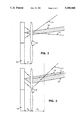
- FIG. 2 is a schematic view of a portion of a system for reconstructing an image from the inventive wallpaper, in which the following reference numerals represent the following elements: 11 is an illuminating wave (a scanning beam); 12 is a set of spherical lenses; 13 is the encoded initial image; and 14 is the reconstructed image.
- 11 is an illuminating wave (a scanning beam)
- 12 is a set of spherical lenses
- 13 is the encoded initial image
- 14 is the reconstructed image.
- FIG. 3 is a schematic view of a variation on the FIG. 2 system, in which illuminating wave 11 is diverging when incident on lenses 12.
- FIG. 4 is a schematic view of the wallpaper under claim, which also includes sound reproducing means, in which the following reference numerals represent the following elements: 21 is wallpaper (having spatially separated copies of a single relief Fourier hologram embossed thereon); 22 is a laser scanning illumination system; 23 is the optical path of the reconstructed image; 24 is the optical path of the sound signal; 25 is a photodetector; 26 is a sound amplifying means; 27 is a loudspeaker; and 28 represents the viewer.
- the claimed object applies the recognized procedures of hologram reconstruction in a new area of application--wallpaper.
- the demands of wallpaper dictate special features and corresponding elements to be incorporated, providing in due order, both the low-powered laser illumination and high-quality image reconstruction.
- the wallpaper under claim utilizes thin-layer holograms.
- the principles of such holograms' recording and reconstructions should be stated briefly, with their advantages emphasized.
- the physically existing object (or its 3-D image for computerized applications especially) is recorded holographically on 2-D media, using a spatial subcarrier/carriers: an angularly deflected, coherent "reference" beam.
- Reconstruction is realized by scanning with a coherent (laser) beam also, resulting in reproduction of the initial 3-D picture, or the image of the object.
- the invention possesses the following advantages: any part of the hologram exactly reconstructs the initial image, and the quality of reconstruction is not affected by the mechanical damage of any kind.
- the method has its drawbacks, based on the required coherent illumination. To produce both good quality and sufficient brightness of the reconstructed image, relatively powerful lasers are needed.
- phase holograms thin-layer holograms being recorded on the phase-relief media
- the diffraction efficiency (or brightness) of which is three to four times greater.
- Their incorporation is based not only on their greater brightness, but also on the simplicity of "printing" the claimed wallpaper.
- the printing process utilizes a small area matrix, which has been precomputerized, and sequentially applied to the corresponding media.
- FIG. 1 This with an additional encoding step is represented by FIG. 1.
- FIG. 1 represents a method for producing the wallpaper of the invention, in which initial 3-D images are supplied to Fourier-transformer 2, the output of element 2 is then supplied to spatial frequency sub-modulation means 3, the output of element 3 is then supplied to combiner 4, the output of combiner 4 is then supplied to binary digitizer 5, and the output of digitizer 5 is supplied to matrix 6.
- Digitizer 5 is included based on the previous works of the inventor. All other steps, excluding the digitizing step, are recognized and easily performed either optically or by the use of computer. In optics for instance, the set of spatial sub-modulators 3 is realized easily by changing the angle of axial orientation of the coherent reference wave. Considering the above, in some cases it is reasonable to produce the combined picture up to step 4 optically, and then to employ a computer for subsequent processing.
- discretizing step 5 which has been additionally introduced.
- the brightness (diffraction efficiency) is the most critical factor
- the use of a discretizing step seems to be most reasonable. While incorporating the computerized processing, this step does not affect either expenses or time. If the discretization step is included the quality of the reconstructed images is not affected. Their brightness is globally maximized and becomes approximately 10 times greater than in the standard holographic reconstruction.
- Step 5 produces the following:
- the resulting image (amplitude or phase, or optical or computer) that represents the set of complex Fourier transforms of initial images (being spatially separated by the use of spatial subcarriers), has been discretized.
- a binary spatial informational sequence is produced.
- the advantages of this procedure in the terms of brightness have been recognized and discussed in published articles of the inventor, and are not repeated here.
- the discretization procedure can be easily implemented optically by incorporating the nonlinearity of recording media.
- the produced binary resulting space pattern (spatial-coordinate representation) is then realized physically as a printing matrix, which can be realized, for instance, as an embossing die.
- a printing matrix which can be realized, for instance, as an embossing die.
- the resulting matrix includes both the spectral information of the initial images (the principle not being widely used in art holograms) and the additional step binary discretization. These are dictated by the special application in the object under claim.
- the printing matrix in one special case, this is an embossing die
- a corresponding medium substrate
- the step of spatial subcarrier informational distribution additionally produces mechanical invulnerability. Though spectral holograms are more susceptible to mechanical damage than are standard holograms, their sequential spatial repetition deals with this also.
- the produced wallpaper when coherently illuminated, produces the desired 3-D effect.
- the procedure for reconstruction of moving images or sets of separate stable images (or both) are discussed below.
- the illumination system should be simple, low cost, and low in intensity
- illuminating scanning beam 11 can be focused in the virtual front focal plane of the said lenses. But then the required positive effect decreases slightly, because the lenses are in reality illuminating by a diverging light beam (see FIG. 3).
- hologram(s) should be realized in the recognized "generalized” modification: the reference beam being made to be converging (when incident at the printing matrix surface), by positioning an additional spherical lens in the reference beam path during the step of registering (synthesizing) said hologram(s).
- the lenses can be algorithmically included in the computerized process, and the printing matrix is to be produced with a spherically curved surface. If this procedure would be algorithmically too complicated, the introduction of the lenses can be realized physically (by affixing lenses to the printed wallpaper) after each step of printing.
- the presence of the lenses serves two purposes:
- the focused illuminating beam, passing through each of the lenses, is subjected to the inverse Fourier transform.
- the latter results in producing a plane wave, which illuminates the holographically encoded image.
- This feature demands the focused illuminating beam, which additionally improves the brightness greatly.
- an inner layer of the wallpaper under claim can be realized as a reflecting surface by a metal coating of the resulting phase hologram.
- the scanning system can be produced inexpensively, with the period of scanning up to 10 -8 sec, with the brightness improving correspondingly.
- This scanning can be realized horizontally or vertically depending on the application.
- a two-coordinate scanning is suggested. It utilizes the recognized two-dimensional properties of spatial spectra.
- the scanning by a second coordinate is involved.
- This scanning is structurally incorporated in the suggested scanning system (only the control signals vary) and is realized either discretely for each of the set of initial images, or continuously for the moving ones, or both.
- the scanning system can easily provide the positioning of all the reconstructed images in the same spatial area (where, for instance, the consumer is situated).
- the principle involved is absolutely the same as in antennae fields (or in antennae with synthesized apertures.
- wallpaper can additionally include sound signals.
- Recording of sound signals on wallpaper in addition to images recorded in the form of digitized Fourier holograms, in the manner described above), and subsequent reconstruction of both the sound signal and image by scanning the wallpaper with a beam in accordance with the invention, does not affect either the complexity, cost, or quality of the image reconstruction.
- a sound signal being a relatively low-frequency signal in comparison with an image, can be included with the image in a combined hologram.
- the sound signal can be reconstructed by the same scanning beam used to reconstruct the image, registered by an additional photodetector, and reproduced by a standard sound amplifying system (in the manner shown in FIG. 4 and described above with reference to FIG. 4).
- the principle involved is absolutely the same as in a conventional CD (audio compact disc) player.
- An attractive feature of audio signal introduction to the inventive wallpaper is that an audio signal may easily be added to an already produced matrix (die).
- the sound pattern recorded on wallpaper in accordance with the invention will of course be a repetitive pattern.
- An embossing process of the type described above may be employed to record both an image (or sequence of images) and an audio signal on wallpaper.
- the invention allows production (and easy reproduction) of wallpaper at low cost, and in a manner so that the wallpaper is insensitive to damage in the following sense. Regardless of the level of mechanical damage to the wallpaper, an image (and/or sound signal) of the same quality may nevertheless be reconstructed by scanning the wallpaper.
Abstract
Description
Claims (20)
Priority Applications (1)
| Application Number | Priority Date | Filing Date | Title |
|---|---|---|---|
| US07/505,428 US5056880A (en) | 1990-04-08 | 1990-04-08 | Holographic wallpaper |
Applications Claiming Priority (1)
| Application Number | Priority Date | Filing Date | Title |
|---|---|---|---|
| US07/505,428 US5056880A (en) | 1990-04-08 | 1990-04-08 | Holographic wallpaper |
Publications (1)
| Publication Number | Publication Date |
|---|---|
| US5056880A true US5056880A (en) | 1991-10-15 |
Family
ID=24010272
Family Applications (1)
| Application Number | Title | Priority Date | Filing Date |
|---|---|---|---|
| US07/505,428 Expired - Fee Related US5056880A (en) | 1990-04-08 | 1990-04-08 | Holographic wallpaper |
Country Status (1)
| Country | Link |
|---|---|
| US (1) | US5056880A (en) |
Cited By (11)
| Publication number | Priority date | Publication date | Assignee | Title |
|---|---|---|---|---|
| WO1994002873A1 (en) * | 1992-07-28 | 1994-02-03 | British Telecommunications Public Limited Company | Optical radiation devices |
| US5291317A (en) * | 1990-07-12 | 1994-03-01 | Applied Holographics Corporation | Holographic diffraction grating patterns and methods for creating the same |
| US5311335A (en) * | 1990-08-03 | 1994-05-10 | Crabtree Allen F | Method for generating holographic images |
| WO1994024615A1 (en) * | 1993-04-21 | 1994-10-27 | Tunnadine Graham Dundas Richmo | Holograms |
| US5706106A (en) * | 1995-05-25 | 1998-01-06 | Pennsylvania Pulp And Paper Co. | Graphic works involving holography |
| US5856048A (en) * | 1992-07-27 | 1999-01-05 | Dai Nippon Printing Co., Ltd. | Information-recorded media and methods for reading the information |
| US6124953A (en) * | 1998-08-17 | 2000-09-26 | Cacciavillano; Frank A. | Wallpaper construction having a holographic border |
| DE19915943A1 (en) * | 1999-04-09 | 2000-10-12 | Ovd Kinegram Ag Zug | Decorative film |
| US20040044382A1 (en) * | 2001-05-23 | 2004-03-04 | Ibrahim Ibrahim Hanna | Transceiver coil for auditory prosthesis |
| US20060180039A1 (en) * | 2004-01-13 | 2006-08-17 | Leite Elizabeth M | Wallpaper effect imprinting device and pattern sheet |
| US20080212181A1 (en) * | 2005-06-16 | 2008-09-04 | Avery Dennison Corporation | Retroreflective Sheet Structure |
Citations (16)
| Publication number | Priority date | Publication date | Assignee | Title |
|---|---|---|---|---|
| US3560072A (en) * | 1968-04-17 | 1971-02-02 | Daniel Silverman | System for the storage,retrieval and display of information |
| US3560071A (en) * | 1968-04-17 | 1971-02-02 | Daniel Silverman | Holographic recording and visual display systems |
| US3719409A (en) * | 1971-11-16 | 1973-03-06 | Bell Telephone Labor Inc | Array of focusing holograms |
| US3772457A (en) * | 1971-03-29 | 1973-11-13 | American Express Invest | Sonic image transducer using a storage camera |
| US3869575A (en) * | 1971-04-02 | 1975-03-04 | Thomson Csf | Speech-synthesis system |
| US3936138A (en) * | 1973-07-18 | 1976-02-03 | Fuji Photo Film Co., Ltd. | Method of reconstructing holograms using a reflected undiffracted beam as a reconstruction beam |
| US3985419A (en) * | 1970-10-05 | 1976-10-12 | Canon Kabushiki Kaisha | Method of making a synthetic focused image hologram |
| US3988572A (en) * | 1974-02-25 | 1976-10-26 | James Nickolas Constant | Synthetic aperture system for information transfer and object identification |
| US4018503A (en) * | 1973-02-01 | 1977-04-19 | Daniel Silverman | Holographic systems having reference beam coded holograms |
| US4125760A (en) * | 1976-08-03 | 1978-11-14 | Lgz Landis & Gyr Zug Ag | Relief pattern impressing apparatus |
| US4206965A (en) * | 1976-08-23 | 1980-06-10 | Mcgrew Stephen P | System for synthesizing strip-multiplexed holograms |
| US4629282A (en) * | 1980-11-05 | 1986-12-16 | Mcgrew Stephen P | Diffractive color and texture effects for the graphic arts |
| US4717221A (en) * | 1980-11-05 | 1988-01-05 | Mcgrew Stephen P | Diffractive color and texture effects for the graphic arts |
| US4758296A (en) * | 1983-06-20 | 1988-07-19 | Mcgrew Stephen P | Method of fabricating surface relief holograms |
| US4778262A (en) * | 1986-10-14 | 1988-10-18 | American Bank Note Holographics, Inc. | Computer aided holography and holographic computer graphics |
| US4832424A (en) * | 1982-09-30 | 1989-05-23 | Mcgrew Stephen P | White-light viewable, cylindrical holograms and method of spatially filtering wavefronts |
-
1990
- 1990-04-08 US US07/505,428 patent/US5056880A/en not_active Expired - Fee Related
Patent Citations (16)
| Publication number | Priority date | Publication date | Assignee | Title |
|---|---|---|---|---|
| US3560071A (en) * | 1968-04-17 | 1971-02-02 | Daniel Silverman | Holographic recording and visual display systems |
| US3560072A (en) * | 1968-04-17 | 1971-02-02 | Daniel Silverman | System for the storage,retrieval and display of information |
| US3985419A (en) * | 1970-10-05 | 1976-10-12 | Canon Kabushiki Kaisha | Method of making a synthetic focused image hologram |
| US3772457A (en) * | 1971-03-29 | 1973-11-13 | American Express Invest | Sonic image transducer using a storage camera |
| US3869575A (en) * | 1971-04-02 | 1975-03-04 | Thomson Csf | Speech-synthesis system |
| US3719409A (en) * | 1971-11-16 | 1973-03-06 | Bell Telephone Labor Inc | Array of focusing holograms |
| US4018503A (en) * | 1973-02-01 | 1977-04-19 | Daniel Silverman | Holographic systems having reference beam coded holograms |
| US3936138A (en) * | 1973-07-18 | 1976-02-03 | Fuji Photo Film Co., Ltd. | Method of reconstructing holograms using a reflected undiffracted beam as a reconstruction beam |
| US3988572A (en) * | 1974-02-25 | 1976-10-26 | James Nickolas Constant | Synthetic aperture system for information transfer and object identification |
| US4125760A (en) * | 1976-08-03 | 1978-11-14 | Lgz Landis & Gyr Zug Ag | Relief pattern impressing apparatus |
| US4206965A (en) * | 1976-08-23 | 1980-06-10 | Mcgrew Stephen P | System for synthesizing strip-multiplexed holograms |
| US4629282A (en) * | 1980-11-05 | 1986-12-16 | Mcgrew Stephen P | Diffractive color and texture effects for the graphic arts |
| US4717221A (en) * | 1980-11-05 | 1988-01-05 | Mcgrew Stephen P | Diffractive color and texture effects for the graphic arts |
| US4832424A (en) * | 1982-09-30 | 1989-05-23 | Mcgrew Stephen P | White-light viewable, cylindrical holograms and method of spatially filtering wavefronts |
| US4758296A (en) * | 1983-06-20 | 1988-07-19 | Mcgrew Stephen P | Method of fabricating surface relief holograms |
| US4778262A (en) * | 1986-10-14 | 1988-10-18 | American Bank Note Holographics, Inc. | Computer aided holography and holographic computer graphics |
Cited By (17)
| Publication number | Priority date | Publication date | Assignee | Title |
|---|---|---|---|---|
| US5291317A (en) * | 1990-07-12 | 1994-03-01 | Applied Holographics Corporation | Holographic diffraction grating patterns and methods for creating the same |
| US5311335A (en) * | 1990-08-03 | 1994-05-10 | Crabtree Allen F | Method for generating holographic images |
| US5856048A (en) * | 1992-07-27 | 1999-01-05 | Dai Nippon Printing Co., Ltd. | Information-recorded media and methods for reading the information |
| GB2284488A (en) * | 1992-07-28 | 1995-06-07 | British Telecomm | Optical radiation devices |
| WO1994002873A1 (en) * | 1992-07-28 | 1994-02-03 | British Telecommunications Public Limited Company | Optical radiation devices |
| US5757523A (en) * | 1992-07-28 | 1998-05-26 | British Telecommunications Public Limited Company | Optical radiation devices |
| WO1994024615A1 (en) * | 1993-04-21 | 1994-10-27 | Tunnadine Graham Dundas Richmo | Holograms |
| US5889598A (en) * | 1995-05-25 | 1999-03-30 | Pennsylvania Pulp And Paper Co. | Graphic works involving holography |
| US5706106A (en) * | 1995-05-25 | 1998-01-06 | Pennsylvania Pulp And Paper Co. | Graphic works involving holography |
| US6124953A (en) * | 1998-08-17 | 2000-09-26 | Cacciavillano; Frank A. | Wallpaper construction having a holographic border |
| DE19915943A1 (en) * | 1999-04-09 | 2000-10-12 | Ovd Kinegram Ag Zug | Decorative film |
| US6602578B1 (en) | 1999-04-09 | 2003-08-05 | Ovd Kinegram Ag | Decorative foil |
| US20040044382A1 (en) * | 2001-05-23 | 2004-03-04 | Ibrahim Ibrahim Hanna | Transceiver coil for auditory prosthesis |
| US20060180039A1 (en) * | 2004-01-13 | 2006-08-17 | Leite Elizabeth M | Wallpaper effect imprinting device and pattern sheet |
| US20080212181A1 (en) * | 2005-06-16 | 2008-09-04 | Avery Dennison Corporation | Retroreflective Sheet Structure |
| US8177374B2 (en) | 2005-06-16 | 2012-05-15 | Avery Dennison Corporation | Retroreflective sheet structure |
| US9308696B2 (en) * | 2005-06-16 | 2016-04-12 | Avery Dennison Corporation | Retroreflective sheet structure |
Similar Documents
| Publication | Publication Date | Title |
|---|---|---|
| Bartolini et al. | HOLOGRAPHY Embossed Hologram Motion Pictures for Television Playback | |
| US5138471A (en) | Holocomposer | |
| US5740276A (en) | Holographic method for encrypting and decrypting information using a fingerprint | |
| US6665108B2 (en) | System for the production of a dynamic image for display | |
| US6538776B2 (en) | Self-referenced holographic storage | |
| US4820006A (en) | Holographic identification system using incoherent light | |
| JPH02500700A (en) | Hybrid opto-electronic content addressable memory | |
| US5056880A (en) | Holographic wallpaper | |
| CN1415083A (en) | Improvements to acquistion and replay system for direct-to-digital holography and holovision | |
| JPH11515110A (en) | Composite hologram copying system and method | |
| JP2002508854A (en) | Direct-digital holography, holographic interferometry, and holographic | |
| Goodman | An introduction to the principles and applications of holography | |
| US3795768A (en) | Holographic image scanner/recorder system | |
| US9013773B2 (en) | Back light unit providing direction controllable collimated light beam and 3D display using the same | |
| JP2718794B2 (en) | Hologram display transmitter | |
| TW479250B (en) | System and method for steering fresnel region data to access data locations in a holographic memory | |
| US6870651B2 (en) | Apparatus and method for generating a dynamic image | |
| WO1984000070A1 (en) | Electronically generated holography | |
| US5767993A (en) | Holographic display transmitting device | |
| US5381249A (en) | Holographic display transmitting device | |
| US3900884A (en) | Holographic color television record system | |
| US3639029A (en) | One-step orthoscopic image reconstructing technique for a hologram constructed through a dispersive medium | |
| Huang et al. | Edge-lit reflection holograms | |
| CN109031916A (en) | A kind of holographic display and method | |
| KR102501363B1 (en) | Hologram replication method and system based on mirror movement |
Legal Events
| Date | Code | Title | Description |
|---|---|---|---|
| AS | Assignment |
Owner name: DZ COMPANY, A CORP. OF CA Free format text: ASSIGNMENT OF ASSIGNORS INTEREST.;ASSIGNOR:BARBANELL, JOSEPH;REEL/FRAME:005282/0477 Effective date: 19900404 |
|
| AS | Assignment |
Owner name: ZELLERBACH, GARY Free format text: ASSIGNMENT OF ASSIGNORS INTEREST.;ASSIGNOR:3 D DAN, INC., DBA THE DZ COMPANY, A CA CORP.;REEL/FRAME:006192/0185 Effective date: 19920630 Owner name: CIFELLI, DAN Free format text: ASSIGNMENT OF ASSIGNORS INTEREST.;ASSIGNOR:3 D DAN, INC., DBA THE DZ COMPANY, A CA CORP.;REEL/FRAME:006192/0185 Effective date: 19920630 |
|
| FPAY | Fee payment |
Year of fee payment: 4 |
|
| REMI | Maintenance fee reminder mailed | ||
| PA | Patent available for licence or sale | ||
| LAPS | Lapse for failure to pay maintenance fees | ||
| FP | Lapsed due to failure to pay maintenance fee |
Effective date: 19991015 |
|
| STCH | Information on status: patent discontinuation |
Free format text: PATENT EXPIRED DUE TO NONPAYMENT OF MAINTENANCE FEES UNDER 37 CFR 1.362 |