US5078367A - Panel system - Google Patents
Panel system Download PDFInfo
- Publication number
- US5078367A US5078367A US07/339,613 US33961389A US5078367A US 5078367 A US5078367 A US 5078367A US 33961389 A US33961389 A US 33961389A US 5078367 A US5078367 A US 5078367A
- Authority
- US
- United States
- Prior art keywords
- panel
- sub
- frame side
- pair
- channel
- Prior art date
- Legal status (The legal status is an assumption and is not a legal conclusion. Google has not performed a legal analysis and makes no representation as to the accuracy of the status listed.)
- Expired - Fee Related
Links
Images


Classifications
-
- E—FIXED CONSTRUCTIONS
- E04—BUILDING
- E04H—BUILDINGS OR LIKE STRUCTURES FOR PARTICULAR PURPOSES; SWIMMING OR SPLASH BATHS OR POOLS; MASTS; FENCING; TENTS OR CANOPIES, IN GENERAL
- E04H17/00—Fencing, e.g. fences, enclosures, corrals
- E04H17/14—Fences constructed of rigid elements, e.g. with additional wire fillings or with posts
- E04H17/16—Fences constructed of rigid elements, e.g. with additional wire fillings or with posts using prefabricated panel-like elements, e.g. wired frames
- E04H17/168—Fences constructed of rigid elements, e.g. with additional wire fillings or with posts using prefabricated panel-like elements, e.g. wired frames using panels fitted in grooves of posts
-
- E—FIXED CONSTRUCTIONS
- E01—CONSTRUCTION OF ROADS, RAILWAYS, OR BRIDGES
- E01F—ADDITIONAL WORK, SUCH AS EQUIPPING ROADS OR THE CONSTRUCTION OF PLATFORMS, HELICOPTER LANDING STAGES, SIGNS, SNOW FENCES, OR THE LIKE
- E01F8/00—Arrangements for absorbing or reflecting air-transmitted noise from road or railway traffic
- E01F8/0005—Arrangements for absorbing or reflecting air-transmitted noise from road or railway traffic used in a wall type arrangement
- E01F8/0011—Plank-like elements
-
- E—FIXED CONSTRUCTIONS
- E01—CONSTRUCTION OF ROADS, RAILWAYS, OR BRIDGES
- E01F—ADDITIONAL WORK, SUCH AS EQUIPPING ROADS OR THE CONSTRUCTION OF PLATFORMS, HELICOPTER LANDING STAGES, SIGNS, SNOW FENCES, OR THE LIKE
- E01F8/00—Arrangements for absorbing or reflecting air-transmitted noise from road or railway traffic
- E01F8/0005—Arrangements for absorbing or reflecting air-transmitted noise from road or railway traffic used in a wall type arrangement
- E01F8/0023—Details, e.g. foundations
-
- E—FIXED CONSTRUCTIONS
- E04—BUILDING
- E04H—BUILDINGS OR LIKE STRUCTURES FOR PARTICULAR PURPOSES; SWIMMING OR SPLASH BATHS OR POOLS; MASTS; FENCING; TENTS OR CANOPIES, IN GENERAL
- E04H17/00—Fencing, e.g. fences, enclosures, corrals
- E04H17/14—Fences constructed of rigid elements, e.g. with additional wire fillings or with posts
- E04H17/16—Fences constructed of rigid elements, e.g. with additional wire fillings or with posts using prefabricated panel-like elements, e.g. wired frames
- E04H17/1602—Using wooden, plastic or composite-material panel-like elements
Definitions
- This invention relates to a panel system, and particularly but not exclusively to a panel system for use as a fencing system. It will be appreciated, however, that the system of the invention is suitable for providing structures other than fencing, for example partitioning, or sheds or similar structures.
- the invention will be described below primarily in relation to a fencing system.
- Conventional fencing systems comprise a plurality of posts arranged at spaced intervals in the ground, the space between each pair of adjacent posts being bridged by a panel secured to the posts.
- the posts can be of wood or concrete, as can the panels. It is also known for concrete panels to be made up from a plurality of sub-panels of manageable size when a single piece panel would be too large and/or heavy to handle. Wooden panels are generally in one piece and are often of such a size that transportation and handling are difficult and expensive. Further, wooden panels and posts require regular treatment in order to prevent decay, and are generally expensive to purchase. Concrete panels and posts are heavy and thus difficult and expensive to handle, even when in sub-panel form, and are also expensive to purchase.
- a panel system comprising a plurality of posts and at least one panel for securing between a pair of adjacent posts, in which each post is formed from plastics material and has a channel in at least one edge to receive an edge portion of a panel, and each panel is formed from plastics material and comprises a frame formed from a plurality of similar cross-section side members secured together at corners of the frame, and a plurality of sub-panels secured within the frame.
- the invention provides a panel system which is cheap and simple to manufacture, easy to erect, light in weight and the components of which can be of such sizes as to be easily transportable.
- the system comprises relatively few different components, and such components can be formed from plastics material by extrusion or injection moulding.
- the sub-panels can be formed to simulate wooden panels, for example panels of the well known lapped form.
- certain of the sub-panels can be formed of transparent or translucent material to provide windows.
- FIG. 1 shows a composite fence panel mounted between a pair of posts assembled from a system according to the invention
- FIG. 2 is a perspective view of a sub-panel of the panel of FIG. 1;
- FIG. 3 is a perspective view of a corner of the frame of the panel of FIG. 1, with part broken away to show the manner in which the side members of the frame are secured together;
- FIG. 4 is an end view of a side member of FIG. 3;
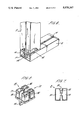
- FIG. 5 is a perspective view of a joint member used in the corner of FIG. 3;
- FIG. 6 is a perspective view of a joint between a side member and an intermediate frame member as used in the panel of FIG. 1, with part broken away to show the manner in which the members are secured together;
- FIG. 7 is an end view of an intermediate member of FIG. 6;
- FIG. 8 is a perspective view of a joint member used in the joint of FIG. 6;
- FIG. 9 is a perspective view of an end portion of a post used in the assembly of FIG. 1;
- FIG. 10 is an end view of the post of FIG. 9;
- FIG. 11 is a perspective view, with part broken away, of a cap for the post of FIG. 9.
- FIG. 12 is a perspective view of an alternative form of panel frame corner joint member.
- FIG. 1 shows a composite fence panel assembled from fifteen sub-panels 1 mounted between four panel frame side members 2, the sub-panels 1 being arranged in three colums each of five sub-panels 1, with the colums being separated by panel frame intermediate members 3.
- the composite panel is mounted between a pair of posts 4, each having a cap 5, the posts being mounted in the ground 100.
- the sub-panels 1 can be formed to simulate overlapping wooden panels, as shown for the lower sub-panels in each column, as trellis panels, as shown at the top of the left hand and centre columns, or as a plain panel, as shown at the top of the right hand column. It will be appreciated that FIG. 1 shows a composite panel in order to show some of the various possible sub-panels, and that for use a panel could be assembled from any desired combination of sub-panels.
- All of the components of the assembly of FIG. 1 are formed of plastics material, and it will be appreciated that in the disassembled state all of the components of the assembly are of such a size as to be easily transportable.
- FIG. 2 shows a typica sub-panel 1 for use in the assembly of FIG. 1.
- the sub-panel 1 is injection moulded from plastics material to simulate three overlapping wooden pieces.
- the sub-panel 1 is substantially planar and rectangular in shape, and has a pair of opposed edge portions in the form of flanges 6 formed with ribs 7, the flanges 6 being for receipt in channels in panel side members as will be described below.
- the other pair of opposed edges of the sub-panel 1 are formed with a tongue 8 and a corresponding slot 9 respectively whereby the tongue 8 of one sub-panel in a column of a panel can be received in the slot 9 of an adjacent sub-panel 1 thereby to secure the sub-panels 1 together at least against relative lateral movement.
- each side member 2 is an elongate hollow section extruded plastics material member having a pair of closed sections 10 with a channel 11 open to one edge of the member 2 extending between them.
- the cross-section of a panel frame side member 2 is clearly shown in FIG. 4.
- the channel 11 is sized to receive the flanges 6 of the sub-panels (see FIG. 2), and as best seen in FIG. 4, has an inner portion 12 of increased width to receive the ribs 7 on the flanges 6 of sub-panels 1.
- the joint member 13 is injection moulded from plastics material and has a first portion 14 for receipt in the channel 11 of a first side member 2, and a second portion 15 for receipt in the hollow section of the second side member 2 at the corner.
- the second portion 15 comprises two hollow projections 16 shaped for receipt in the two closed sections 10 of a side member 2 respectively.
- Each projections 16 is of stepped shape providing a free end portion 17 of relatively small cross-section for ease of insertion into a hollow section 10 of a side member 2, and an inner portion 18 of relatively large cross-section for gripping by the hollow section 10 of a side member 2 after insertion thereinto.
- the first portion 14 of the joint member 13 is shaped to engage in the increased width portion 12 in the channel 11 in a side member 2 whereby the joint member 13 becomes secured in the channel 11 when the first portion 14 is inserted therein.
- FIG. 6 shows a joint between a side member 2 and a panel frame intermediate member 3 of the assembly of FIG. 1.
- the joint is similar to that shown in FIG. 3, and corresponding parts and features have been given the same reference numerals as in FIG. 3.
- the intermediate member 3 is an elongate hollow section plastics material extrusion having basically the form of a pair of panel frame side members 2 as shown in FIG. 3 arranged back-to-back, whereby the intermediate member 3 provides a pair of opposed channels 11 for receipt of the flanges 6 on sub-panels 1.
- the cross-section of the intermediate member 3 is clearly shown in FIG. 7.
- the joint of FIG. 6 uses a joint member 13 similar to that of FIG. 5 except that the second portion 15 thereof comprises four hollow projections 16 instead of two.
- this shows a post 4 of the assembly of FIG. 1, the post 4 being an elongate hollow section plastics material extrusion, having a cross-section as shown in FIG. 10, filled with a rigid foamed plastics material core 19.
- a pair of opposed sides of the post 4 are each formed with a longitudinally extending channel 20 for receipt of an edge portion of a panel as shown in FIG. 1.
- the channel 20 in fact receives the side member 2 at the edge of the panel and thus the joints at the corners of the panel are concealed within and protected by the walls of the channel 20.
- FIG. 11 shows a cap 21 for mounting on top of the post 4 of FIG. 9, the cap 21 being moulded from plastics material and having four pairs of co-operating flanges 22 and 23 arranged such that one flange 22 enages the inside surface of a side wall of the post 4 while the other flange 23 engages the outside surface thereof in opposed manner wherby the side wall is gripped between the flanges 22 and 23.
- the inner flanges 22 are formed with tapered edges to assist in penetration of the core 19 of the post 4.
- FIG. 12 shows an alternative form of joint member 24 for joining side members 2 at the corners of a panel.
- This joint member 24 is moulded from plastics material and has a rectanguloid body 25 from which project two pairs of hollow projections 26, the pairs extending at right angles relative to each other.
- the projections 26 are received in the hollow sections 10 at the ends of a pair of side members 2 thereby to form a corner joint.
- the projections 26 can if desired be shaped as are the projections 16 of the joint member 13 of FIG. 3.
Abstract
Description
Claims (29)
Applications Claiming Priority (2)
| Application Number | Priority Date | Filing Date | Title |
|---|---|---|---|
| GB878718210A GB8718210D0 (en) | 1987-07-31 | 1987-07-31 | Fencing system |
| GB8718210 | 1987-07-31 |
Publications (1)
| Publication Number | Publication Date |
|---|---|
| US5078367A true US5078367A (en) | 1992-01-07 |
Family
ID=10621643
Family Applications (1)
| Application Number | Title | Priority Date | Filing Date |
|---|---|---|---|
| US07/339,613 Expired - Fee Related US5078367A (en) | 1987-07-31 | 1988-07-28 | Panel system |
Country Status (8)
| Country | Link |
|---|---|
| US (1) | US5078367A (en) |
| EP (1) | EP0327625B1 (en) |
| AU (1) | AU2088088A (en) |
| CA (1) | CA1309609C (en) |
| DE (1) | DE3868045D1 (en) |
| GB (2) | GB8718210D0 (en) |
| NZ (1) | NZ225616A (en) |
| WO (1) | WO1989001085A2 (en) |
Cited By (69)
| Publication number | Priority date | Publication date | Assignee | Title |
|---|---|---|---|---|
| US5419536A (en) * | 1993-02-26 | 1995-05-30 | Bender; Richard | Fence post cap |
| US5421556A (en) * | 1993-03-02 | 1995-06-06 | Associated Materials Inc. | Modular fencing components |
| US5441240A (en) * | 1993-03-24 | 1995-08-15 | Arnold; James L. | Fence panel assembly and fence |
| US5445362A (en) * | 1994-02-25 | 1995-08-29 | Reppert; Francis J. | Fence assembly |
| US5468436A (en) * | 1993-04-22 | 1995-11-21 | Kirtland; Ralph | Continuous feed, low pressure process for manufacturing thermoplastic posts |
| WO1995033614A1 (en) * | 1994-06-02 | 1995-12-14 | The Tensar Corporation | Panel framing system and products produced thereby |
| US5480126A (en) * | 1994-03-23 | 1996-01-02 | Soniplastics Inc. | Fencing construction |
| USD378462S (en) * | 1995-09-01 | 1997-03-11 | Erwin Industries, Inc. | Mailbox post with support arm |
| US5620136A (en) * | 1995-10-24 | 1997-04-15 | Erwin Industries, Inc. | Foam-filled plastic mailbox post |
| US5645270A (en) * | 1996-06-24 | 1997-07-08 | Lawrence; Lloyd L. | Plastic component connection system |
| US5657967A (en) * | 1994-04-21 | 1997-08-19 | Patrick; Thomas D. | Ecological confinement option |
| US5660016A (en) * | 1995-04-26 | 1997-08-26 | Ronald Dean Erwin | Foam-filled extruded decking plank and decking attachment system |
| US5660376A (en) * | 1995-05-01 | 1997-08-26 | West; Ronald R. | Cap and mounting for a fence system |
| USD385682S (en) * | 1995-10-25 | 1997-10-28 | Erwin Industries, Inc. | Mailbox with auxiliary slot |
| US5702090A (en) * | 1995-08-07 | 1997-12-30 | Vinylex Corporation | Snap together plastic fence |
| US5713165A (en) * | 1995-04-26 | 1998-02-03 | Erwin Industries, Inc. | Foam-filled extruded plastic decking with non-slip surface coating |
| US6076807A (en) * | 1997-07-16 | 2000-06-20 | Spence; Jonathan P. | Fence or deck post cap |
| USD427322S (en) * | 1999-08-24 | 2000-06-27 | U.S. Fence Llc | Fence section |
| GB2350625A (en) * | 1999-04-13 | 2000-12-06 | Michael John Hills | Plastics fencing system |
| US6190084B1 (en) * | 1998-05-12 | 2001-02-20 | CONSTRUCCIONES MECáNICAS MARéS, S.A. | Modular separating barrier element |
| EP1156178A2 (en) * | 2000-05-17 | 2001-11-21 | Intermas Nets, S.A. | Partition former for inhabitable spaces and use thereof |
| US6431526B1 (en) * | 1998-05-01 | 2002-08-13 | Dofasco Inc. | Railing components and methods of making railings |
| US6443432B1 (en) * | 1999-09-09 | 2002-09-03 | Robert C. Manno | Structures made of corrugated-like plastic & method of manufacture and use |
| US6540445B1 (en) | 2001-03-01 | 2003-04-01 | Eldon Boyd Evans, Jr. | Concrete silt fence |
| US6550216B1 (en) | 2000-04-21 | 2003-04-22 | Harout Ohanesian | Storage shed |
| GB2382597A (en) * | 2001-10-30 | 2003-06-04 | Frederick Leonard Hatswell | Plastics snap fit fence assembly |
| US20030136066A1 (en) * | 2001-03-30 | 2003-07-24 | Akihiro Kishimoto | Office forming equipment |
| US20030230026A1 (en) * | 2002-06-17 | 2003-12-18 | Ed Dillon | Modular garden fencing |
| US6688583B2 (en) | 2000-01-03 | 2004-02-10 | Tmc, Inc. | Fence post finials |
| US20040187415A1 (en) * | 2003-03-27 | 2004-09-30 | Chen Chang Than | Plastic post assembly for mailbox |
| US6804921B2 (en) | 2001-12-10 | 2004-10-19 | Associated Materials, Inc. | Cap for tubular construction components and connector |
| US6851660B1 (en) * | 2002-11-06 | 2005-02-08 | Michael Thomas Cravatt | Landscape timber anchoring system |
| US20050160692A1 (en) * | 2004-01-28 | 2005-07-28 | Vaughn Henry G. | Decorative railing assembly for a building and methods for manufacturing same |
| US6935623B2 (en) | 2001-09-14 | 2005-08-30 | Crane Plastics Company Llc | Fence assembly with connectors |
| US20060118771A1 (en) * | 2004-12-02 | 2006-06-08 | Robert Stein | Interlocking privacy fence |
| US7134646B1 (en) * | 2004-09-14 | 2006-11-14 | Brooks Roy C | Privacy fence system |
| US20060284154A1 (en) * | 2005-06-16 | 2006-12-21 | Gary Sprague | Component railing system and method of installation |
| US20070012904A1 (en) * | 2005-06-28 | 2007-01-18 | Westech Building Products, Inc. | Fence system |
| US20070090334A1 (en) * | 2005-10-21 | 2007-04-26 | Laws David J | Molded decorative fence panel |
| US20070158629A1 (en) * | 2002-06-18 | 2007-07-12 | Laws David J | Rotationally molded, reinforced decorative fence post and method of making same |
| US20070275229A1 (en) * | 2003-12-12 | 2007-11-29 | Laws R D | Molded article with foam-encased adhesion-resistant reinforcing member and method |
| US20070278468A1 (en) * | 2006-06-06 | 2007-12-06 | Zacarias Felix M | Novel modular molded frame with interchangeable design panels for vinyl fencing and its method of fabrication |
| US20080083915A1 (en) * | 2006-10-04 | 2008-04-10 | Ken Trascher | Security barrier |
| US20090152523A1 (en) * | 2007-12-18 | 2009-06-18 | Erwin Ronald D | Snap-together fencing components |
| US20100237308A1 (en) * | 2009-03-23 | 2010-09-23 | Chong-Yi Lo | Fence |
| US20100283022A1 (en) * | 2009-02-03 | 2010-11-11 | Warren Delafield | Modular Railing Systems with Cellular PVC Panels |
| US20100314597A1 (en) * | 2009-06-16 | 2010-12-16 | Wilbar International, Inc. | Barrier fence system |
| US20110140062A1 (en) * | 2009-12-11 | 2011-06-16 | Alpa Lumer Inc. | Adjustable baluster assembly |
| US20110315941A1 (en) * | 2008-12-24 | 2011-12-29 | Jenkin Timber Limited | Fence |
| DE202011109530U1 (en) * | 2011-12-24 | 2013-03-25 | Sehnix Gmbh | Wall element for a noise barrier |
| US8783661B1 (en) * | 2005-01-07 | 2014-07-22 | Betafence Usa Llc | Fence system |
| US20160030855A1 (en) * | 2014-07-30 | 2016-02-04 | Solowave Design Lp | Play center |
| USD758611S1 (en) | 2015-04-10 | 2016-06-07 | N. Eric Knudsen | Fence panel |
| US9506270B2 (en) * | 2014-08-14 | 2016-11-29 | N. Eric Knudsen | Fence panel systems and methods |
| US9932753B1 (en) | 2017-06-14 | 2018-04-03 | N. Eric Knudsen | Fence panel systems and methods |
| USD834258S1 (en) * | 2016-09-30 | 2018-11-20 | Shock Doctor, Inc. | Mouthguard |
| USD839485S1 (en) | 2017-07-14 | 2019-01-29 | Shock Doctor, Inc. | Mouthguard |
| USD841257S1 (en) | 2017-07-14 | 2019-02-19 | Shock Doctor, Inc. | Mouthguard |
| USD854753S1 (en) | 2017-12-15 | 2019-07-23 | Shock Doctor, Inc. | Mouthguard |
| USD857301S1 (en) | 2017-12-15 | 2019-08-20 | Shock Doctor, Inc. | Mouth guard |
| US10774576B1 (en) | 2017-10-20 | 2020-09-15 | Ameristar Perimeter Security Usa Inc. | Gate assembly |
| USD916382S1 (en) | 2016-09-27 | 2021-04-13 | Shock Doctor, Inc. | Mouthguard |
| US11179622B2 (en) | 2018-01-10 | 2021-11-23 | Shock Doctor, Inc. | Mouthguard with tapered breathing channel |
| US20210381271A1 (en) * | 2020-06-05 | 2021-12-09 | Barrette Outdoor Living, Inc. | System and method for vertical and horizontal in-fill installation |
| US11273360B2 (en) | 2016-09-30 | 2022-03-15 | Shock Doctor, Inc. | Mouthguard including a protection portion having heating and softening features |
| US20220133061A1 (en) * | 2020-11-03 | 2022-05-05 | Top Victory Investments Limited | Connecting device |
| USD963950S1 (en) | 2020-01-28 | 2022-09-13 | Shock Doctor, Inc. | Mouthguard |
| US11499337B2 (en) | 2017-11-14 | 2022-11-15 | Vision Extrusions Group Limited | Fence panel system |
| USD977148S1 (en) * | 2020-10-16 | 2023-01-31 | Roderick Blackett | Panel kit |
Families Citing this family (8)
| Publication number | Priority date | Publication date | Assignee | Title |
|---|---|---|---|---|
| GB2234272A (en) * | 1989-07-19 | 1991-01-30 | Mr | A screen wall assembly |
| AU650223B3 (en) * | 1993-02-05 | 1994-06-09 | Tudor Lodge Pty. Ltd. | A panel |
| GB2278375A (en) * | 1993-05-27 | 1994-11-30 | Raymond Price | Glass fibre reinforced fencing panels |
| FR2710934A1 (en) * | 1993-10-07 | 1995-04-14 | Metalluplast | Aluminium post with double slide to facilitate the fitting of a grill |
| FR2757224A1 (en) * | 1996-12-12 | 1998-06-19 | Extrusion Sogex Soc Gen | Frame for barrier fence |
| FR2841281B1 (en) | 2002-06-25 | 2004-09-17 | Rene Michel Verschuere | FENCE ELEMENTS INCLUDING H-PROFILES AND POSITIONING BRACKETS |
| WO2007096627A1 (en) * | 2006-02-22 | 2007-08-30 | Varley And Gulliver Limited | Structural support system |
| FR2958674B3 (en) * | 2010-04-08 | 2012-04-20 | R & J Solar Corp | ADJUSTABLE CLOSURE |
Citations (10)
| Publication number | Priority date | Publication date | Assignee | Title |
|---|---|---|---|---|
| FR398359A (en) * | 1909-01-08 | 1909-06-03 | Gustav Schlechtweg | Fence formed by means of slotted piles and boards slipped into these slits |
| US3274641A (en) * | 1963-02-28 | 1966-09-27 | Alfred A Smith | Apparatus and method for making crutch pads |
| US3600867A (en) * | 1969-10-16 | 1971-08-24 | Bernice W Shuey | Building block construction and assemblage |
| US3799506A (en) * | 1972-04-14 | 1974-03-26 | G Schwartz | Fence |
| FR2331658A1 (en) * | 1975-11-13 | 1977-06-10 | Pamesa Ets | Temporary excavation storage hopper - has unit sizes of corrugated wall slotted between rectangular tubular uprights |
| FR2338368A1 (en) * | 1975-11-07 | 1977-08-12 | Pamesa Ets | REMOVABLE Palisade |
| GB1522724A (en) * | 1977-02-18 | 1978-08-31 | Formica Int | Structural assembly |
| DE2752618A1 (en) * | 1977-11-22 | 1979-05-23 | Westeel Rosco Ltd | COMBINED STRUCTURE |
| NL8400058A (en) * | 1984-01-06 | 1985-08-01 | Some Vena Bv | Moulded plastics fencing frame - has extruded profiled uprights and long boards engaging protruding parts of uprights |
| US4602765A (en) * | 1984-04-23 | 1986-07-29 | Loper Karl J | Fencing assembly and process |
Family Cites Families (7)
| Publication number | Priority date | Publication date | Assignee | Title |
|---|---|---|---|---|
| US2057018A (en) * | 1936-05-12 | 1936-10-13 | Dillon George Wilson | Fence |
| GB662696A (en) * | 1949-06-21 | 1951-12-12 | Martin Parry Corp | Wall or partition structures |
| FR1335524A (en) * | 1961-05-09 | 1963-08-23 | Sicedison Spa | Dismountable and reconstructable partition wall, formed by the assembly of several shaped elements entirely in plastic material |
| US3698692A (en) * | 1971-04-26 | 1972-10-17 | Clinton A Burrows Jr | Modular fence construction |
| AU486419B2 (en) * | 1973-03-06 | 1974-09-12 | L.B. (Plastics) Ltd. | Improvements in and relating to fencing |
| GB2035409A (en) * | 1978-10-13 | 1980-06-18 | Livens J | Improvements in or relating to fencing |
| NZ222442A (en) * | 1986-11-07 | 1991-05-28 | Shiavello Bros Vic Pty Ltd | Partition panel |
-
1987
- 1987-07-31 GB GB878718210A patent/GB8718210D0/en active Pending
-
1988
- 1988-07-28 US US07/339,613 patent/US5078367A/en not_active Expired - Fee Related
- 1988-07-28 WO PCT/GB1988/000625 patent/WO1989001085A2/en active IP Right Grant
- 1988-07-28 DE DE8888906956T patent/DE3868045D1/en not_active Expired - Fee Related
- 1988-07-28 GB GB8818043A patent/GB2207452B/en not_active Expired - Fee Related
- 1988-07-28 EP EP88906956A patent/EP0327625B1/en not_active Expired - Lifetime
- 1988-07-28 AU AU20880/88A patent/AU2088088A/en not_active Abandoned
- 1988-07-29 NZ NZ225616A patent/NZ225616A/en unknown
- 1988-07-29 CA CA000573413A patent/CA1309609C/en not_active Expired - Fee Related
Patent Citations (13)
| Publication number | Priority date | Publication date | Assignee | Title |
|---|---|---|---|---|
| FR398359A (en) * | 1909-01-08 | 1909-06-03 | Gustav Schlechtweg | Fence formed by means of slotted piles and boards slipped into these slits |
| US3274641A (en) * | 1963-02-28 | 1966-09-27 | Alfred A Smith | Apparatus and method for making crutch pads |
| US3600867A (en) * | 1969-10-16 | 1971-08-24 | Bernice W Shuey | Building block construction and assemblage |
| US3799506A (en) * | 1972-04-14 | 1974-03-26 | G Schwartz | Fence |
| GB1544915A (en) * | 1975-11-07 | 1979-04-25 | Pamesa Ets | Fence |
| FR2338368A1 (en) * | 1975-11-07 | 1977-08-12 | Pamesa Ets | REMOVABLE Palisade |
| FR2331658A1 (en) * | 1975-11-13 | 1977-06-10 | Pamesa Ets | Temporary excavation storage hopper - has unit sizes of corrugated wall slotted between rectangular tubular uprights |
| GB1522724A (en) * | 1977-02-18 | 1978-08-31 | Formica Int | Structural assembly |
| DE2752618A1 (en) * | 1977-11-22 | 1979-05-23 | Westeel Rosco Ltd | COMBINED STRUCTURE |
| US4202532A (en) * | 1977-11-22 | 1980-05-13 | Westeel-Rosco Limited Westeel-Rosco Limitee | Jointed structure, combination of members therefor, and method of disassembly thereof |
| GB1598134A (en) * | 1977-11-22 | 1981-09-16 | Westeel Rosco Ltd | Jointed structure components therefor and method of disassembly thereof |
| NL8400058A (en) * | 1984-01-06 | 1985-08-01 | Some Vena Bv | Moulded plastics fencing frame - has extruded profiled uprights and long boards engaging protruding parts of uprights |
| US4602765A (en) * | 1984-04-23 | 1986-07-29 | Loper Karl J | Fencing assembly and process |
Cited By (98)
| Publication number | Priority date | Publication date | Assignee | Title |
|---|---|---|---|---|
| US5419536A (en) * | 1993-02-26 | 1995-05-30 | Bender; Richard | Fence post cap |
| US5421556A (en) * | 1993-03-02 | 1995-06-06 | Associated Materials Inc. | Modular fencing components |
| US5628494A (en) * | 1993-03-24 | 1997-05-13 | Arnold; James L. | Fence panel assembly and fence |
| US5441240A (en) * | 1993-03-24 | 1995-08-15 | Arnold; James L. | Fence panel assembly and fence |
| US5468436A (en) * | 1993-04-22 | 1995-11-21 | Kirtland; Ralph | Continuous feed, low pressure process for manufacturing thermoplastic posts |
| US5445362A (en) * | 1994-02-25 | 1995-08-29 | Reppert; Francis J. | Fence assembly |
| US5480126A (en) * | 1994-03-23 | 1996-01-02 | Soniplastics Inc. | Fencing construction |
| US5657967A (en) * | 1994-04-21 | 1997-08-19 | Patrick; Thomas D. | Ecological confinement option |
| WO1995033614A1 (en) * | 1994-06-02 | 1995-12-14 | The Tensar Corporation | Panel framing system and products produced thereby |
| US5660016A (en) * | 1995-04-26 | 1997-08-26 | Ronald Dean Erwin | Foam-filled extruded decking plank and decking attachment system |
| US5728330A (en) * | 1995-04-26 | 1998-03-17 | Irwin Industries, Inc. | Process for manufacturing foam-filled extruded products |
| US5713165A (en) * | 1995-04-26 | 1998-02-03 | Erwin Industries, Inc. | Foam-filled extruded plastic decking with non-slip surface coating |
| US5660376A (en) * | 1995-05-01 | 1997-08-26 | West; Ronald R. | Cap and mounting for a fence system |
| US5702090A (en) * | 1995-08-07 | 1997-12-30 | Vinylex Corporation | Snap together plastic fence |
| USD378462S (en) * | 1995-09-01 | 1997-03-11 | Erwin Industries, Inc. | Mailbox post with support arm |
| US5620136A (en) * | 1995-10-24 | 1997-04-15 | Erwin Industries, Inc. | Foam-filled plastic mailbox post |
| US5806758A (en) * | 1995-10-24 | 1998-09-15 | Erwin Industries, Inc. | Process for manufacturing foam-filled plastic mailbox post |
| USD385682S (en) * | 1995-10-25 | 1997-10-28 | Erwin Industries, Inc. | Mailbox with auxiliary slot |
| US5645270A (en) * | 1996-06-24 | 1997-07-08 | Lawrence; Lloyd L. | Plastic component connection system |
| US6076807A (en) * | 1997-07-16 | 2000-06-20 | Spence; Jonathan P. | Fence or deck post cap |
| US6431526B1 (en) * | 1998-05-01 | 2002-08-13 | Dofasco Inc. | Railing components and methods of making railings |
| US6190084B1 (en) * | 1998-05-12 | 2001-02-20 | CONSTRUCCIONES MECáNICAS MARéS, S.A. | Modular separating barrier element |
| GB2350625A (en) * | 1999-04-13 | 2000-12-06 | Michael John Hills | Plastics fencing system |
| GB2350625B (en) * | 1999-04-13 | 2003-10-22 | Michael John Hills | Fencing system |
| USD427322S (en) * | 1999-08-24 | 2000-06-27 | U.S. Fence Llc | Fence section |
| US6443432B1 (en) * | 1999-09-09 | 2002-09-03 | Robert C. Manno | Structures made of corrugated-like plastic & method of manufacture and use |
| US6688583B2 (en) | 2000-01-03 | 2004-02-10 | Tmc, Inc. | Fence post finials |
| US6550216B1 (en) | 2000-04-21 | 2003-04-22 | Harout Ohanesian | Storage shed |
| EP1156178A3 (en) * | 2000-05-17 | 2003-10-22 | Intermas Nets, S.A. | Partition former for inhabitable spaces and use thereof |
| EP1156178A2 (en) * | 2000-05-17 | 2001-11-21 | Intermas Nets, S.A. | Partition former for inhabitable spaces and use thereof |
| US6540445B1 (en) | 2001-03-01 | 2003-04-01 | Eldon Boyd Evans, Jr. | Concrete silt fence |
| US20030136066A1 (en) * | 2001-03-30 | 2003-07-24 | Akihiro Kishimoto | Office forming equipment |
| US6786014B2 (en) * | 2001-03-30 | 2004-09-07 | Kokuyo Co., Ltd. | Office forming equipment |
| US6935623B2 (en) | 2001-09-14 | 2005-08-30 | Crane Plastics Company Llc | Fence assembly with connectors |
| GB2382597A (en) * | 2001-10-30 | 2003-06-04 | Frederick Leonard Hatswell | Plastics snap fit fence assembly |
| US6804921B2 (en) | 2001-12-10 | 2004-10-19 | Associated Materials, Inc. | Cap for tubular construction components and connector |
| US20030230026A1 (en) * | 2002-06-17 | 2003-12-18 | Ed Dillon | Modular garden fencing |
| US20070158629A1 (en) * | 2002-06-18 | 2007-07-12 | Laws David J | Rotationally molded, reinforced decorative fence post and method of making same |
| US7635114B2 (en) | 2002-06-18 | 2009-12-22 | Mfs, Llc | Rotationally molded, reinforced decorative fence post and method of making same |
| US6851660B1 (en) * | 2002-11-06 | 2005-02-08 | Michael Thomas Cravatt | Landscape timber anchoring system |
| US20040187415A1 (en) * | 2003-03-27 | 2004-09-30 | Chen Chang Than | Plastic post assembly for mailbox |
| US6883285B2 (en) * | 2003-03-27 | 2005-04-26 | Chang Than Chen | Plastic post assembly for mailbox |
| US20070275229A1 (en) * | 2003-12-12 | 2007-11-29 | Laws R D | Molded article with foam-encased adhesion-resistant reinforcing member and method |
| US20050160692A1 (en) * | 2004-01-28 | 2005-07-28 | Vaughn Henry G. | Decorative railing assembly for a building and methods for manufacturing same |
| US7134646B1 (en) * | 2004-09-14 | 2006-11-14 | Brooks Roy C | Privacy fence system |
| US20060118771A1 (en) * | 2004-12-02 | 2006-06-08 | Robert Stein | Interlocking privacy fence |
| US9428934B1 (en) | 2005-01-07 | 2016-08-30 | Betafence Usa Llc | Fence system |
| US8783661B1 (en) * | 2005-01-07 | 2014-07-22 | Betafence Usa Llc | Fence system |
| US8944414B2 (en) * | 2005-06-16 | 2015-02-03 | C.R. Laurence Company, Inc. | Component railing system and method of installation |
| US20060284154A1 (en) * | 2005-06-16 | 2006-12-21 | Gary Sprague | Component railing system and method of installation |
| US7934699B2 (en) * | 2005-06-28 | 2011-05-03 | Westech Building Products, Inc. | Fence system |
| US20070012904A1 (en) * | 2005-06-28 | 2007-01-18 | Westech Building Products, Inc. | Fence system |
| US20070090334A1 (en) * | 2005-10-21 | 2007-04-26 | Laws David J | Molded decorative fence panel |
| US7478797B2 (en) * | 2005-10-21 | 2009-01-20 | Mfs, Llc | Molded decorative fence panel |
| US20070278468A1 (en) * | 2006-06-06 | 2007-12-06 | Zacarias Felix M | Novel modular molded frame with interchangeable design panels for vinyl fencing and its method of fabrication |
| US20080083915A1 (en) * | 2006-10-04 | 2008-04-10 | Ken Trascher | Security barrier |
| US20090152523A1 (en) * | 2007-12-18 | 2009-06-18 | Erwin Ronald D | Snap-together fencing components |
| US8794598B2 (en) * | 2008-12-24 | 2014-08-05 | Jenkin Timber Limited | Fence |
| US20110315941A1 (en) * | 2008-12-24 | 2011-12-29 | Jenkin Timber Limited | Fence |
| US20100283022A1 (en) * | 2009-02-03 | 2010-11-11 | Warren Delafield | Modular Railing Systems with Cellular PVC Panels |
| US10190331B2 (en) * | 2009-02-03 | 2019-01-29 | Warren Delafield | Modular railing systems with cellular PVC panels |
| US20100237308A1 (en) * | 2009-03-23 | 2010-09-23 | Chong-Yi Lo | Fence |
| US20100314597A1 (en) * | 2009-06-16 | 2010-12-16 | Wilbar International, Inc. | Barrier fence system |
| US20110140062A1 (en) * | 2009-12-11 | 2011-06-16 | Alpa Lumer Inc. | Adjustable baluster assembly |
| US8579263B2 (en) * | 2009-12-11 | 2013-11-12 | Alpa Lumber Inc. | Adjustable baluster assembly |
| DE202011109530U1 (en) * | 2011-12-24 | 2013-03-25 | Sehnix Gmbh | Wall element for a noise barrier |
| US20160030855A1 (en) * | 2014-07-30 | 2016-02-04 | Solowave Design Lp | Play center |
| US9821246B2 (en) * | 2014-07-30 | 2017-11-21 | Solowave Design Lp | Play center |
| US9506270B2 (en) * | 2014-08-14 | 2016-11-29 | N. Eric Knudsen | Fence panel systems and methods |
| US10487535B2 (en) | 2014-08-14 | 2019-11-26 | N. Eric Knudsen | Fence panel systems and methods |
| USD758611S1 (en) | 2015-04-10 | 2016-06-07 | N. Eric Knudsen | Fence panel |
| USD797308S1 (en) | 2015-04-10 | 2017-09-12 | N. Eric Knudsen | Fence panel |
| USD916382S1 (en) | 2016-09-27 | 2021-04-13 | Shock Doctor, Inc. | Mouthguard |
| US11878232B2 (en) | 2016-09-30 | 2024-01-23 | Shock Doctor, Inc. | Mouthguard including a protection portion having heating and softening features |
| USD834258S1 (en) * | 2016-09-30 | 2018-11-20 | Shock Doctor, Inc. | Mouthguard |
| US11273360B2 (en) | 2016-09-30 | 2022-03-15 | Shock Doctor, Inc. | Mouthguard including a protection portion having heating and softening features |
| USD917102S1 (en) | 2016-09-30 | 2021-04-20 | Shock Doctor, Inc. | Mouthguard |
| US10167653B1 (en) | 2017-06-14 | 2019-01-01 | N. Eric Knudsen | Fence panel systems and methods |
| US9932753B1 (en) | 2017-06-14 | 2018-04-03 | N. Eric Knudsen | Fence panel systems and methods |
| USD841257S1 (en) | 2017-07-14 | 2019-02-19 | Shock Doctor, Inc. | Mouthguard |
| USD839485S1 (en) | 2017-07-14 | 2019-01-29 | Shock Doctor, Inc. | Mouthguard |
| US11414916B1 (en) | 2017-10-20 | 2022-08-16 | Ameristar Perimeter Sercurity USA Inc. | Gate assembly |
| US10774576B1 (en) | 2017-10-20 | 2020-09-15 | Ameristar Perimeter Security Usa Inc. | Gate assembly |
| US10900281B1 (en) | 2017-10-20 | 2021-01-26 | Ameristar Perimeter Security Usa Inc. | Gate assembly |
| US11499337B2 (en) | 2017-11-14 | 2022-11-15 | Vision Extrusions Group Limited | Fence panel system |
| USD857301S1 (en) | 2017-12-15 | 2019-08-20 | Shock Doctor, Inc. | Mouth guard |
| USD854753S1 (en) | 2017-12-15 | 2019-07-23 | Shock Doctor, Inc. | Mouthguard |
| USRE48988E1 (en) | 2017-12-15 | 2022-03-29 | Shock Doctor, Inc. | Mouthguard |
| USD869774S1 (en) | 2017-12-15 | 2019-12-10 | Shock Doctor, Inc. | Mouthguard |
| USD867673S1 (en) | 2017-12-15 | 2019-11-19 | Shock Doctor, Inc. | Mouthguard |
| US11179622B2 (en) | 2018-01-10 | 2021-11-23 | Shock Doctor, Inc. | Mouthguard with tapered breathing channel |
| US11701568B2 (en) | 2018-01-10 | 2023-07-18 | Shock Doctor, Inc. | Mouthguard with tapered breathing channel |
| USD963950S1 (en) | 2020-01-28 | 2022-09-13 | Shock Doctor, Inc. | Mouthguard |
| US20210381271A1 (en) * | 2020-06-05 | 2021-12-09 | Barrette Outdoor Living, Inc. | System and method for vertical and horizontal in-fill installation |
| US11891832B2 (en) * | 2020-06-05 | 2024-02-06 | Barrette Outdoor Living, Inc. | System and method for vertical and horizontal in-fill installation |
| USD977148S1 (en) * | 2020-10-16 | 2023-01-31 | Roderick Blackett | Panel kit |
| US20220133061A1 (en) * | 2020-11-03 | 2022-05-05 | Top Victory Investments Limited | Connecting device |
| US11849868B2 (en) * | 2020-11-03 | 2023-12-26 | Top Victory Investments Limited | Connecting device |
Also Published As
| Publication number | Publication date |
|---|---|
| EP0327625B1 (en) | 1992-01-22 |
| AU2088088A (en) | 1989-03-01 |
| DE3868045D1 (en) | 1992-03-05 |
| NZ225616A (en) | 1991-11-26 |
| GB8718210D0 (en) | 1987-09-09 |
| WO1989001085A2 (en) | 1989-02-09 |
| WO1989001085A3 (en) | 1989-02-23 |
| EP0327625A1 (en) | 1989-08-16 |
| GB2207452A (en) | 1989-02-01 |
| GB2207452B (en) | 1991-12-04 |
| CA1309609C (en) | 1992-11-03 |
| GB8818043D0 (en) | 1988-09-01 |
Similar Documents
| Publication | Publication Date | Title |
|---|---|---|
| US5078367A (en) | Panel system | |
| US4007919A (en) | Fence structure | |
| US3964810A (en) | Modular shelf and cabinet system | |
| US5527103A (en) | Cabinet of improved design and construction | |
| US6004182A (en) | Temporary structure | |
| US5097643A (en) | Interlocking structural members with edge connectors | |
| US5313751A (en) | Interlocking structural members with edge connectors | |
| US7654060B2 (en) | Reinforced blow-molded plastic panels and structures | |
| US3477184A (en) | Educational playhouse | |
| US4175883A (en) | Composite structural members and fastening methods | |
| US20100050556A1 (en) | Panel Structure | |
| US5174078A (en) | Roof construction for playhouse | |
| US4521203A (en) | Toy construction kit | |
| US3050287A (en) | Woven panel fence | |
| US5193603A (en) | Display framing apparatus | |
| US6146232A (en) | Toy logs having novel shape | |
| US4594828A (en) | Building construction system including a profile extrusion used as a universal structural member and assembly clips therefor | |
| JP2756894B2 (en) | Dome-shaped building | |
| US11277978B2 (en) | Vinyl raised bed garden planter kit with modular extension option | |
| US6655106B1 (en) | Corner studs for prefabricated building systems | |
| US20050144859A1 (en) | Construction kit | |
| GB1571153A (en) | Building elements for children's play houses | |
| GB2087452A (en) | Temporary Structure | |
| GB2154549A (en) | Container | |
| GB2336610A (en) | A display arrangement with columns and beams secured by inter-engaging formations |
Legal Events
| Date | Code | Title | Description |
|---|---|---|---|
| AS | Assignment |
Owner name: BISON HOUSEFLOOR LIMITED A CORP. OF THE UNITED K Free format text: ASSIGNMENT OF ASSIGNORS INTEREST.;ASSIGNOR:PLAS-LAP LIMITED A CORP. OF UNITED KINGDOM;REEL/FRAME:005836/0832 Effective date: 19910829 Owner name: PLAS-LAP LIMITED A CORP. OF THE UNITED KINGDOM, U Free format text: ASSIGNMENT OF ASSIGNORS INTEREST.;ASSIGNORS:SIMPSON, ALAN G.;SIMPSON, IAN A.;REEL/FRAME:005836/0829 Effective date: 19910814 |
|
| REMI | Maintenance fee reminder mailed | ||
| LAPS | Lapse for failure to pay maintenance fees | ||
| FP | Lapsed due to failure to pay maintenance fee |
Effective date: 19960110 |
|
| STCH | Information on status: patent discontinuation |
Free format text: PATENT EXPIRED DUE TO NONPAYMENT OF MAINTENANCE FEES UNDER 37 CFR 1.362 |