US5079696A - Apparatus for read handshake in high-speed asynchronous bus interface - Google Patents
Apparatus for read handshake in high-speed asynchronous bus interface Download PDFInfo
- Publication number
- US5079696A US5079696A US07/405,543 US40554389A US5079696A US 5079696 A US5079696 A US 5079696A US 40554389 A US40554389 A US 40554389A US 5079696 A US5079696 A US 5079696A
- Authority
- US
- United States
- Prior art keywords
- computer system
- data
- bus
- clock
- read
- Prior art date
- Legal status (The legal status is an assumption and is not a legal conclusion. Google has not performed a legal analysis and makes no representation as to the accuracy of the status listed.)
- Expired - Lifetime
Links
Images


Classifications
-
- G—PHYSICS
- G06—COMPUTING; CALCULATING OR COUNTING
- G06F—ELECTRIC DIGITAL DATA PROCESSING
- G06F13/00—Interconnection of, or transfer of information or other signals between, memories, input/output devices or central processing units
- G06F13/38—Information transfer, e.g. on bus
- G06F13/42—Bus transfer protocol, e.g. handshake; Synchronisation
- G06F13/4204—Bus transfer protocol, e.g. handshake; Synchronisation on a parallel bus
- G06F13/4208—Bus transfer protocol, e.g. handshake; Synchronisation on a parallel bus being a system bus, e.g. VME bus, Futurebus, Multibus
- G06F13/4213—Bus transfer protocol, e.g. handshake; Synchronisation on a parallel bus being a system bus, e.g. VME bus, Futurebus, Multibus with asynchronous protocol
Definitions
- This invention relates to computer circuitry and, more particularly, to handshake circuitry at a computer bus interface for connecting asynchronous clocked modules.
- the typical interface system for transferring information between two computer systems or modules is a synchronous interface system, one in which the two systems are operated by the same clock.
- Joining the two system is usually a data bus for carrying information, an address bus for carrying addresses, and control lines for accomplishing a so-called "handshake" between the two systems.
- a write line, a read line, and an acknowledge line are required for transferring signals between the two systems to accomplish the handshake operation.
- the computer system wishing to read information from a second system provides a read signal on the read control line during a first clock period.
- the second system samples the read line connecting the two systems during a second clock period, finds the data at the address designated and places the data on the data bus during a period defined by the address of the particular data, and finally returns an acknowledge pulse on the acknowledge line to indicate that the data is at the data bus ready to be transferred.
- an additional clock period is necessary to terminate the original read signal, and another clock period to terminate the acknowledge signal.
- the read handshake operation the data must be found at some address of the second system before it may be transferred to the requesting system. Consequently, a read handshake operation cannot utilize the same sort of pipeline circuitry used in the write handshake to remove the delay caused by synchronization between two asynchronous systems from the interface. This is true for two reasons. First, as explained, the read data is not immediately available (as is the write information) so the data cannot be immediately transferred. Second, obtaining the data from different addresses may take different lengths of time which may depend on the particular address to be read or may depend on the current status of the read device itself Data at one address may be available immediately, data at another address may be available in one clock period, data at another address may be available in two clock periods, and so on. In fact, the time in which it takes to obtain certain data may not be even ascertainable until the data has been obtained.
- a read signal is provided by the requesting system, synchronized through two stages of flip-flops, and the system furnishing the data begins to obtain the data in response to the signal.
- the data is obtained, it is placed on the data bus for transmitting to the requesting system; and, an acknowledge signal is sent to the requesting system and synchronized through two additional stages of flip-flops.
- a read handshake circuitry for an asynchronous bus interface system transferring data between first and second computer systems which comprises means for providing signals to indicate to the second computer system that the first system desires to read data at a specified address of the second system, means for comparing the specified address with addresses of the second system to provide an output indicating the time required to retrieve data from the specified address, and means operative in response to the output indicating the time required to retrieve data for providing a coded signal from the second computer system to the first computer system to indicate to the first computer system the time at which the information will be available for transfer to the first computer system.
- FIG. 1(a) is a block diagram illustrating a prior art interface system for connecting together two systems running synchronously.
- FIG. 1(b) is a timing diagram illustrating the signals utilized in the handshake operation for the interface system illustrated in FIG. 1(a).
- FIG. 2(a) illustrates in block diagram form prior art circuitry for accomplishing the transfer of information in the handshake operation in between two asynchronous systems.
- FIG. 2(b) illustrates a timing diagram showing the signals utilized for accomplishing a handshake in an asynchronous write handshake operation as shown in FIG. 2(a).
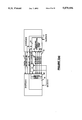
- FIG. 3(a) illustrates in block diagram form an interface system constructed in accordance with the present invention.
- FIG. 3(b) illustrates a timing diagram for the operation of the interface system shown in FIG. 3(a).
- FIG. 3(c) illustrates an exemplary coding of signals used in the operation of the interface system shown in FIG. 3(a).
- FIGS. 4(a) and 4(b) illustrate the precise manner in which the different delays may be made to fit an interface for systems operating at two different specified clock frequencies.
- the manipulations performed are often referred to in terms, such as adding or comparing, which are commonly associated with mental operations performed by a human operator. No such capability of a human operator is necessary or desirable in most cases in any of the operations described herein which form part of the present invention; the operations are machine operations.
- Useful machines for performing the operations of the present invention include general purpose digital computers or other similar devices. In all cases the distinction between the method operations in operating a computer and the method of computation itself should be borne in mind.
- the present invention relates to apparatus and to method steps for operating a computer in processing electrical or other (e.g. mechanical, chemical) physical signals to generate other desired physical signals.
- FIG. 1(a) is a block diagram illustrating a synchronous interface system for connecting together two systems running on the same clock.
- System A and System B are connected together by a data bus 11 which, in the preferred embodiment, may comprise thirty-two lines for carrying data.
- Also connecting system A to system B are a write line 12, a read line 13, and an acknowledge line 14.
- a system clock appears on line 15 and is furnished to state machines 16 and 17 which control the handshake operation between System A and System B.
- state machine refers to a digital logic state machine, a processor such as a central processing unit, or some other circuitry providing control functions.
- address bus 18 for conveying addressing information between the systems A and B.
- FIG. 1(b) is a timing diagram which illustrates the signals utilized in a typical full handshake read operation. These include a clock signal which is furnished to each of the state machines 16 and 17 of System A and System B on the clock line 15, a read signal provided on the read line 13, and an acknowledge signal provided on the acknowledge line 14.
- a read signal is provided by the state machine 16 on the read line 13 following the rising edge of the first clock pulse 100 and the address of the data to be read is placed on the address bus 18.
- the read signal is sampled by the state machine 17 of System B and the address of the data to be read is read by system B from the address bus 18.
- the state machine 17 of the system B it is necessary for the state machine 17 of the system B to obtain the data from the addressed space. This may take any of a number of different time lengths. For example, data at an address at one point in the system B may require one clock period to obtain while data at another address may require several clock periods. The time required to obtain information at some addresses may not, in fact, be pre-determinable. Once the information has been found, it is transferred onto the data bus 11. In FIG. 1(b) the varying time required to obtain the data and place it on the data bus 11 is indicated by the broken lines in the latter portion of the second clock period 101.
- an acknowledge signal is sent indicating data has been placed on the data bus 11 and is ready to be read by the system A.
- the acknowledge signal is read by the state machine 16 of system A on the leading edge of the next clock pulse 108 allowing the termination of the read signal to occur. Finally, the acknowledge signal may be terminated following the leading edge of the next clock pulse 109.
- FIG. 2(a) illustrates in block diagram form the typical circuitry in the prior art for accomplishing the read handshake operation between two asynchronous systems, i.e., systems running on different system clocks.
- system A operates in a response to a first clock A while system B operates in response to a second clock B.
- System A is joined to system B by a data bus 11 and an address bus 18, and has read line 13 and acknowledge line 14 for accomplishing the read handshake between the two systems.
- Also included in the normal interface but not shown in FIG. 2(a) is identical circuitry for accomplishing the read handshake operation in an opposite direction; since the operation is the same, only circuitry for transferring in one direction is illustrated.
- the two systems A and B are driven by two different clocks so that signals which are sent from system A appear at one rate but can be used at system B only at a second rate and vice versa, it is necessary to synchronize the signals transferred between the two systems to the clocks of the receiving systems.
- a pair of flip-flops are used in each handshake line.
- the state machine 16 of system A places a read signal on read line 13.
- the read signal on read line 13 is transferred to the input of a first flip-flop 20 which is driven by clock B.
- the output of the flip-flop 20 is transferred to flip-flop 21 which is also driven by clock B and then to the state machine 17 of system B.
- the data is accessed and placed on the data bus 11, and an acknowledge signal is placed on the acknowledge line 14.
- the acknowledge signal from the state machine 17 of system B are furnished to a first flip-flop 23 driven by clock A.
- the output of the flip-flop 23 is furnished to a flip-flop 25 which is also driven by clock A and furnishes an output to the state machine 16 of the system A.
- FIG. 2(b) illustrates a timing diagram showing the signals utilized for accomplishing a handshake in an asynchronous full handshake read operation between system A and system B of the prior art.
- the signals shown are clock A, the read signal, clock B, the acknowledge signal, the address information, and the data information.
- the read signal from state machine 16 is driven active on the read line 13.
- the read pulse is provided to the first flip-flop 20 which attempts to assume a set state.
- the particular state the flip-flop 20 actually takes will depend on the timing of the appearance of the read signal and the B clock pulse. If there is sufficient set-up and hold time for the incoming read signal to stabilize at the input to the flip-flop 20 when the clock pulse is received, the flip-flop 20 will set; and the read signal will be synchronized with the clock of the system B.
- the first flip-flop 20 may, in fact, assume a metastable condition, switching erratically between the two possible states and finally settling into one of the states. Ultimately, it will assume one or the other of its two states. If this is the correct set state, the read signal will be synchronized with the clock of the system B producing an output to set the flip-flop 21. If not, the next clock will set the flip-flop 20 and synchronize the read signal although one additional clock period has been used.
- the output of the flip-flop 20 responding to the read signal provides an output to place the second flip-flop 21 into the same state.
- the flip-flop 21 is arranged in the path in order to isolate any erratic switching of the state of the flip-flop 20 from the state machine 17 of the receiving system B.
- the use of two stages of flip-flops to receive the handshake signals adds at least two additional clock periods to each step of the synchronization in an asynchronous interface designed in accordance with the prior art.
- the read signal is synchronized to the clock of system B, and the state machine B may sample the read line.
- the address of the data to be read, placed on the address bus 18, may now be read by system B.
- the state machine 17 of the system B it is necessary for the state machine 17 of the system B to obtain the data from the addressed space. This may take any of a number of different time lengths. In FIG. 2(b) the time required for this operation is considered to fall within the period between the broken lines after the third clock period 252 of clock B. Once the information has been found, it is transferred onto the data bus 11.
- the acknowledge signal may be sent.
- the acknowledge signal is provided by the state machine 17 to the first flip-flop 23 on the acknowledge line 14.
- the diagram presumes on the rising edge of the clock pulse 207 of clock A successfully sets flip-flop 23 and the second flip-flop 25 on the rising edge of the clock pulse 208 of clock A. At this time, the acknowledge signal is considered synchronized with the clock A of system A.
- the acknowledge signal may be sampled by the state machine 16 of system A and the read pulse driven negative (deasserted) on the read line 13.
- the state machine 17 may deassert the acknowledge signal on the acknowledge line 14.
- the deassertion of the acknowledge signal causes the attempted change of state of the flip-flop 23 on the rising edge of the clock pulse 214 of clock A and a change of state of flip-flop 25 on the rising edge of the clock pulse 215 of clock A.
- the state machine 16 of system A samples the deassertion of the acknowledge signal on the rising edge of clock pulse 216 of clock A.
- a read signal is provided by the system A, synchronized through two stages of flip-flops, and sampled by system B.
- System B then reads the address and begins to obtain the data in response to the signal.
- the data is obtained by system B, it is placed on the data bus to system A, and an acknowledge signal is sent to system A and synchronized through two stages of flip-flops. Later the deassertion of the read and the acknowledge signals must each again be synchronized through two stages of flip-flops.
- FIG. 3(a) illustrates an arrangement in block diagram form constructed in accordance with the invention.
- the arrangement includes a first system A which operates on a first clock A, a second system B which operates on a second clock B, a read line 40, a data bus 47, an address bus 48, and a plurality of acknowledge lines 41-45.
- Each of the individual acknowledge lines 41-44 may carry a zero or a one bit.
- the present system stores the addresses of the second system and the known times for retrieval associated with each of such addresses, compares the address on the bus with the stored addresses to generate a signal indicating the time for retrieval of data at the particular address, transmits coded signals indicating those times to the sending system, decodes the signals representing the delays so that the receiving system may be prepared at the indicated time to receive the information, and provides standard synchronization for those few addresses the time for retrieval of information from which is unknown.
- each read signal sent by the state machine 16 of the system A on the line 40 is directed to an encoding combinational array logic circuit 51 in the state machine of system B.
- the address transferred on the address bus 48 from system A to system B is also directed to the encoding combinational array logic circuit 51.
- Almost all addresses of system B will (in the usual case) have known time delays for the retrieval of information in response to a read request. As pointed out above, some of these delays may be short while others are long.
- the encoding combinational array logic circuit 51 of system B receives the address sent on the address bus 48 and the read signal and generates an encoded delay for the particular address. This delay is sent on the acknowledge lines 41 through 44 to the state machine 16 as a coded response indicating the specified delay time.
- decode combinational logic circuit 50 residing in state machine 16.
- the data at the addressed position will have been placed on the data bus 47 and may be immediately utilized by system A if state machine 116 determines from the decoded delay that the read data has sufficient setup time to clock A.
- FIG. 3(b) illustrates a timing diagram illustrating the clock A, clock B, address and data information, the read pulse, and the acknowledge signal as they appear on the specified lines of the interface between systems A and B.
- the address is placed on the address bus 48 and the read signal is asserted on the read line 40 by the state machine 16 of system A.
- the read signal and the address are connected to encoding combination logic circuit 51.
- the logic circuit 51 generates the coded acknowledge signals which are immediately placed on the lines 41-44 at the state machine 17 of system B.
- the address on the address bus 48 and the read signal together generate the encoded acknowledge signals specifying the delay for the specified address.
- These are placed on the acknowledge lines 41-44 and within a single clock period of clock A cause the decode combinational logic 50 of the state machine 16 to provide to the state machine 16 the specific delay for the address.
- the state machine 16 may sample the output of the decode combinational logic 50 so that it knows the time at which the data will be available on the data bus 47. After the specified delay (shown below the data signal in FIG. 3(b)), the data is placed on the data line 47 in response to the rising edge of clock pulse 356 of clock B.
- the data is read by system A; and, at clock pulse 308 of clock A, the address and the read signals are deasserted. Since these are directly connected through the combinational logic of the circuit 51, the acknowledge signals are removed from the acknowledge lines 41-44. At the same time, the data is removed from the data bus 47. It should be noted that at no time has it been necessary to utilize the clock B pulses at all in accomplishing the synchronization except in clocking the data onto the data bus 47.
- FIG. 3(c) illustrates an exemplary coding of the signals appearing on the lines 41-44 in order to specify the particular delays.
- the time for the retrieval of information for transfer to system A is unknown.
- This coded information signifies to the system A that synchronization will require that the usual form of two flip-flop synchronization be accomplished between system A and B by the line 45.
- the unknown delay situation is an unusual situation and will occur infrequently in the usual operation of synchronizing two computer systems.
- the method and signals for accomplishing such a synchronization are in accordance with the description provided for FIGS. 2(a) and 2(b).
- the combinational logic circuit 51 will generate and cause a one to appear on line 41 and zeros to appear on lines 42-44 to indicate this.
- a one appearing on line 42 and zeroes on the other lines will indicate that the delay is twenty nanoseconds
- ones on lines 41 and 42 and zeroes on the other lines will indicate a thirty nanosecond delay
- a one on line 43 and zeroes on the other lines will indicate a forty second nanosecond delay, and so on. It will be noted that using this exemplary coding arrangement with delays spaced by ten nanoseconds allows retrieval times from ten nanoseconds to one hundred fifty nanoseconds to be specified by four acknowledge lines.
- FIGS. 4(a) and 4(b) illustrate the precise manner in which the different delays may be made to fit two different clock cycles, one of thirty-three nanoseconds per clock period and another of forty-three nanoseconds per clock period. For example, if a single clock period of thirty-three nanoseconds is necessary to obtain data at a particular address, a forty nanosecond delay is signalled on the acknowledge lines 41-44. If two clock periods of thirty-three nanoseconds are necessary to obtain data, a delay of seventy nanoseconds is signalled on the acknowledge lines 41-44. In like manner, if one clock period of forty-three nanoseconds is necessary to obtain addressed data, a delay of fifty nanoseconds is signalled by the acknowledge lines 41-44.
Abstract
Description
Claims (12)
Priority Applications (4)
| Application Number | Priority Date | Filing Date | Title |
|---|---|---|---|
| US07/405,543 US5079696A (en) | 1989-09-11 | 1989-09-11 | Apparatus for read handshake in high-speed asynchronous bus interface |
| GB9007818A GB2235995B (en) | 1989-09-11 | 1990-04-06 | Apparatus for read handshake in high-speed asynchronous bus interface |
| SG124993A SG124993G (en) | 1989-09-11 | 1993-11-23 | Apparatus for read handshake in high-speed asynchronous bus interface |
| HK36994A HK36994A (en) | 1989-09-11 | 1994-04-21 | Apparatus for read handshake in high-speed asynchronous bus interface |
Applications Claiming Priority (1)
| Application Number | Priority Date | Filing Date | Title |
|---|---|---|---|
| US07/405,543 US5079696A (en) | 1989-09-11 | 1989-09-11 | Apparatus for read handshake in high-speed asynchronous bus interface |
Publications (1)
| Publication Number | Publication Date |
|---|---|
| US5079696A true US5079696A (en) | 1992-01-07 |
Family
ID=23604134
Family Applications (1)
| Application Number | Title | Priority Date | Filing Date |
|---|---|---|---|
| US07/405,543 Expired - Lifetime US5079696A (en) | 1989-09-11 | 1989-09-11 | Apparatus for read handshake in high-speed asynchronous bus interface |
Country Status (3)
| Country | Link |
|---|---|
| US (1) | US5079696A (en) |
| GB (1) | GB2235995B (en) |
| HK (1) | HK36994A (en) |
Cited By (15)
| Publication number | Priority date | Publication date | Assignee | Title |
|---|---|---|---|---|
| US5191657A (en) * | 1989-11-09 | 1993-03-02 | Ast Research, Inc. | Microcomputer architecture utilizing an asynchronous bus between microprocessor and industry standard synchronous bus |
| US5255375A (en) * | 1992-01-10 | 1993-10-19 | Digital Equipment Corporation | High performance interface between an asynchronous bus and one or more processors or the like |
| US5265216A (en) * | 1991-06-28 | 1993-11-23 | Digital Equipment Corporation | High performance asynchronous bus interface |
| US5333301A (en) * | 1990-12-14 | 1994-07-26 | International Business Machines Corporation | Data transfer bus system and method serving multiple parallel asynchronous units |
| US5388225A (en) * | 1992-09-16 | 1995-02-07 | Texas Instruments Incorporated | Time-domain boundary bridge method and apparatus for asynchronous sequential machines |
| US5412783A (en) * | 1991-11-10 | 1995-05-02 | Hewlett-Packard Company | Method for efficient serialized transmission of handshake signal on a digital bus |
| US5461723A (en) * | 1990-04-05 | 1995-10-24 | Mit Technology Corp. | Dual channel data block transfer bus |
| US5469547A (en) * | 1992-07-17 | 1995-11-21 | Digital Equipment Corporation | Asynchronous bus interface for generating individual handshake signal for each data transfer based on associated propagation delay within a transaction |
| US5471672A (en) * | 1991-07-25 | 1995-11-28 | Intel Corporation | Method for implementing a high speed computer graphics bus |
| US5555213A (en) * | 1995-06-29 | 1996-09-10 | Rockwell International Corporation | Interface circuit, system and method for interfacing an electronic device and a synchronous state machine having different clock speeds |
| US5590275A (en) * | 1992-02-18 | 1996-12-31 | U.S. Philips Corporation | Method for testing an integrated circuitry and an integrated circuit having a plurality of functional components and having junction/switch test components in interconnecting channels between functional components |
| US5798667A (en) * | 1994-05-16 | 1998-08-25 | At&T Global Information Solutions Company | Method and apparatus for regulation of power dissipation |
| US20060013167A1 (en) * | 2004-07-19 | 2006-01-19 | Wheatley Paul J | Slow-fast programming of distributed base stations in a wireless network |
| US9341676B2 (en) | 2011-10-07 | 2016-05-17 | Alcatel Lucent | Packet-based propagation of testing information |
| US9489009B2 (en) | 2014-02-20 | 2016-11-08 | Samsung Electronics Co., Ltd. | System on chip, bus interface and method of operating the same |
Families Citing this family (1)
| Publication number | Priority date | Publication date | Assignee | Title |
|---|---|---|---|---|
| US5418930A (en) * | 1991-09-05 | 1995-05-23 | International Business Machines Corporation | Circuit for interfacing asynchronous to synchronous communications |
Citations (3)
| Publication number | Priority date | Publication date | Assignee | Title |
|---|---|---|---|---|
| GB1098890A (en) * | 1965-05-05 | 1968-01-10 | Rca Corp | Computer peripheral device control |
| GB1287657A (en) * | 1969-07-09 | 1972-09-06 | Burroughs Corp | Apparatus for signalling peripheral unit configuration within computer system |
| US4809217A (en) * | 1985-10-31 | 1989-02-28 | Allen-Bradley Company, Inc. | Remote I/O port for transfer of I/O data in a programmable controller |
-
1989
- 1989-09-11 US US07/405,543 patent/US5079696A/en not_active Expired - Lifetime
-
1990
- 1990-04-06 GB GB9007818A patent/GB2235995B/en not_active Expired - Fee Related
-
1994
- 1994-04-21 HK HK36994A patent/HK36994A/en not_active IP Right Cessation
Patent Citations (3)
| Publication number | Priority date | Publication date | Assignee | Title |
|---|---|---|---|---|
| GB1098890A (en) * | 1965-05-05 | 1968-01-10 | Rca Corp | Computer peripheral device control |
| GB1287657A (en) * | 1969-07-09 | 1972-09-06 | Burroughs Corp | Apparatus for signalling peripheral unit configuration within computer system |
| US4809217A (en) * | 1985-10-31 | 1989-02-28 | Allen-Bradley Company, Inc. | Remote I/O port for transfer of I/O data in a programmable controller |
Cited By (18)
| Publication number | Priority date | Publication date | Assignee | Title |
|---|---|---|---|---|
| US5191657A (en) * | 1989-11-09 | 1993-03-02 | Ast Research, Inc. | Microcomputer architecture utilizing an asynchronous bus between microprocessor and industry standard synchronous bus |
| US5555381A (en) * | 1989-11-09 | 1996-09-10 | Ast Research, Inc. | Microcomputer architecture utilizing an asynchronous bus between microprocessor and industry standard synchronous bus |
| US5461723A (en) * | 1990-04-05 | 1995-10-24 | Mit Technology Corp. | Dual channel data block transfer bus |
| US5333301A (en) * | 1990-12-14 | 1994-07-26 | International Business Machines Corporation | Data transfer bus system and method serving multiple parallel asynchronous units |
| US5265216A (en) * | 1991-06-28 | 1993-11-23 | Digital Equipment Corporation | High performance asynchronous bus interface |
| US5471672A (en) * | 1991-07-25 | 1995-11-28 | Intel Corporation | Method for implementing a high speed computer graphics bus |
| US5412783A (en) * | 1991-11-10 | 1995-05-02 | Hewlett-Packard Company | Method for efficient serialized transmission of handshake signal on a digital bus |
| US5255375A (en) * | 1992-01-10 | 1993-10-19 | Digital Equipment Corporation | High performance interface between an asynchronous bus and one or more processors or the like |
| US5590275A (en) * | 1992-02-18 | 1996-12-31 | U.S. Philips Corporation | Method for testing an integrated circuitry and an integrated circuit having a plurality of functional components and having junction/switch test components in interconnecting channels between functional components |
| US5469547A (en) * | 1992-07-17 | 1995-11-21 | Digital Equipment Corporation | Asynchronous bus interface for generating individual handshake signal for each data transfer based on associated propagation delay within a transaction |
| US5388225A (en) * | 1992-09-16 | 1995-02-07 | Texas Instruments Incorporated | Time-domain boundary bridge method and apparatus for asynchronous sequential machines |
| US5798667A (en) * | 1994-05-16 | 1998-08-25 | At&T Global Information Solutions Company | Method and apparatus for regulation of power dissipation |
| US5555213A (en) * | 1995-06-29 | 1996-09-10 | Rockwell International Corporation | Interface circuit, system and method for interfacing an electronic device and a synchronous state machine having different clock speeds |
| US20060013167A1 (en) * | 2004-07-19 | 2006-01-19 | Wheatley Paul J | Slow-fast programming of distributed base stations in a wireless network |
| US7602729B2 (en) * | 2004-07-19 | 2009-10-13 | Alcatel-Lucent Usa Inc. | Slow-fast programming of distributed base stations in a wireless network |
| US9341676B2 (en) | 2011-10-07 | 2016-05-17 | Alcatel Lucent | Packet-based propagation of testing information |
| US9489009B2 (en) | 2014-02-20 | 2016-11-08 | Samsung Electronics Co., Ltd. | System on chip, bus interface and method of operating the same |
| US9811482B2 (en) | 2014-02-20 | 2017-11-07 | Samsung Electronics Co., Ltd. | Asynchronous interface in a system on chip and a method of operating the same |
Also Published As
| Publication number | Publication date |
|---|---|
| GB2235995B (en) | 1993-07-28 |
| HK36994A (en) | 1994-04-29 |
| GB9007818D0 (en) | 1990-06-06 |
| GB2235995A (en) | 1991-03-20 |
Similar Documents
| Publication | Publication Date | Title |
|---|---|---|
| US5079696A (en) | Apparatus for read handshake in high-speed asynchronous bus interface | |
| US5070443A (en) | Apparatus for write handshake in high-speed asynchronous bus interface | |
| US4390969A (en) | Asynchronous data transmission system with state variable memory and handshaking protocol circuits | |
| EP0666541A1 (en) | Apparatus and method for operating chips synchronously at speeds exceeding the bus speed | |
| US4412286A (en) | Tightly coupled multiple instruction multiple data computer system | |
| JPH02227765A (en) | Data transfer apparatus for digital computer | |
| US4048673A (en) | Cpu - i/o bus interface for a data processing system | |
| US5745793A (en) | Apparatus having a circular buffer that maintains a one entry gap between elements written to the microprocessor and elements operated on by the clock | |
| EP1019838B1 (en) | Fast 16-bit, split transaction i/o bus | |
| JPS6073774A (en) | Interface circuit | |
| JPH0713926A (en) | Buffer control circuit and its operating method | |
| US5524112A (en) | Interface apparatus for transferring k*n-bit data packets via transmission of K discrete n-bit parallel words and method therefore | |
| US3967246A (en) | Digital computer arrangement for communicating data via data buses | |
| US20060047754A1 (en) | Mailbox interface between processors | |
| JPH06259225A (en) | Synchronizer of data transfer | |
| US5535343A (en) | Method and apparatus for generating write signals | |
| US6170027B1 (en) | LPC/ISA bridge and its bridging method | |
| US20050055489A1 (en) | Bridge circuit for use in retiming in a semiconductor integrated circuit | |
| US6546451B1 (en) | Method and apparatus for decoupling processor speed from memory subsystem speed in a node controller | |
| US20030005344A1 (en) | Synchronizing data with a capture pulse and synchronizer | |
| WO1981002798A1 (en) | Computer system and interface therefor | |
| GB1581838A (en) | I/o bus transceiver for a data processing system | |
| GB2060961A (en) | Data processing system having memory modules with distributed address information | |
| JPH04279945A (en) | Memory circuit | |
| US3417374A (en) | Computer-controlled data transferring buffer |
Legal Events
| Date | Code | Title | Description |
|---|---|---|---|
| AS | Assignment |
Owner name: SUN MICROSYSTEMS, INC., CALIFORNIA Free format text: ASSIGNMENT OF ASSIGNORS INTEREST.;ASSIGNORS:PRIEM, CURTIS;MALACHOWSKY, CHRIS;REEL/FRAME:005131/0935 Effective date: 19890906 |
|
| AS | Assignment |
Owner name: SUN MICROSYSTEMS, INC., 2550 GARCIA AVE., MOUNTAIN Free format text: ASSIGNMENT OF ASSIGNORS INTEREST.;ASSIGNORS:PRIEM, CURTIS;MALACHOWSKY, CHRIS;REEL/FRAME:005392/0178 Effective date: 19900423 |
|
| STCF | Information on status: patent grant |
Free format text: PATENTED CASE |
|
| FEPP | Fee payment procedure |
Free format text: PAYOR NUMBER ASSIGNED (ORIGINAL EVENT CODE: ASPN); ENTITY STATUS OF PATENT OWNER: LARGE ENTITY |
|
| FPAY | Fee payment |
Year of fee payment: 4 |
|
| FPAY | Fee payment |
Year of fee payment: 8 |
|
| FEPP | Fee payment procedure |
Free format text: PAYER NUMBER DE-ASSIGNED (ORIGINAL EVENT CODE: RMPN); ENTITY STATUS OF PATENT OWNER: LARGE ENTITY Free format text: PAYOR NUMBER ASSIGNED (ORIGINAL EVENT CODE: ASPN); ENTITY STATUS OF PATENT OWNER: LARGE ENTITY |
|
| FPAY | Fee payment |
Year of fee payment: 12 |
|
| REMI | Maintenance fee reminder mailed |