US5081546A - Vehicle exterior mirror - Google Patents
Vehicle exterior mirror Download PDFInfo
- Publication number
- US5081546A US5081546A US07/556,296 US55629690A US5081546A US 5081546 A US5081546 A US 5081546A US 55629690 A US55629690 A US 55629690A US 5081546 A US5081546 A US 5081546A
- Authority
- US
- United States
- Prior art keywords
- pair
- bracket means
- pivot axis
- ribs
- washer
- Prior art date
- Legal status (The legal status is an assumption and is not a legal conclusion. Google has not performed a legal analysis and makes no representation as to the accuracy of the status listed.)
- Expired - Fee Related
Links
Images

Classifications
-
- B—PERFORMING OPERATIONS; TRANSPORTING
- B60—VEHICLES IN GENERAL
- B60R—VEHICLES, VEHICLE FITTINGS, OR VEHICLE PARTS, NOT OTHERWISE PROVIDED FOR
- B60R1/00—Optical viewing arrangements; Real-time viewing arrangements for drivers or passengers using optical image capturing systems, e.g. cameras or video systems specially adapted for use in or on vehicles
- B60R1/02—Rear-view mirror arrangements
- B60R1/06—Rear-view mirror arrangements mounted on vehicle exterior
- B60R1/0605—Rear-view mirror arrangements mounted on vehicle exterior specially adapted for mounting on trucks, e.g. by C-shaped support means
- B60R1/0617—Rear-view mirror arrangements mounted on vehicle exterior specially adapted for mounting on trucks, e.g. by C-shaped support means foldable along the vehicle, e.g. in case of external force applied thereon
Definitions
- This invention relates to an exterior rear view mirror for a motor vehicle of the type comprising bracket means adapted to be secured to the vehicle body, and a housing containing a reflective member and having first and second support elements each of which is pivotally connected to the bracket means for relative angular movement about a pivot axis, the pivotal connection between the second support element and the bracket means including detent means adapted to hold the housing at a predetermined orientation relative to the bracket means, the second support element being movable relative to the bracket means parallel to the pivot axis to effect engagement and disengagement of the detent means, and resilient means being arranged to urge the detent formations into engagement.
- each support element comprises an arm projecting laterally from the housing.
- the two arms may be widely spaced from one another with each pivotally connected to a separate bracket adapted to be secured to the vehicle body.
- one arm may be located above the mirror housing and the other below it.
- the two arms may be relatively close to one another, the bracket means consisting of a single bracket to which both are pivotally connected.
- any misalignment between the pivot axes of the two pivot joints can prevent the detent formations coming into full engagement with one another with the result that there is free play between the arms and the bracket means.
- the present invention aims to provide a mirror assembly which is not subject to this disadvantage.
- the detent means comprises a first pair of detent formations on the second support element diametrically spaced on opposite sides of the pivot axis and adapted to engage with a first pair of complementary formations on one face of a washer located between the second support element and the bracket means, and a second pair of detent formations on the opposite face of the washer diametrically spaced apart from one another relative to the pivot axis and orientated at 90 to the first pair of complementary formations, the second pair of detent formations being adapted to engage with a second pair of complementary formations on the bracket means.
- the washer is capable of limited angular movement relative to the second support element about a first axis perpendicular to the pivot axis and is capable of similar limited angular movement relative to the bracket means about a second axis perpendicular both to the pivot axis and the first axis, thus allowing all the detent formations to engage fully with their respective complementary formations even if misalignment of the pivot axis of the first support element causes the second support element to be twisted so that the face thereof carrying the first detent formations is not truly parallel to the face of the bracket means carrying the second complementary formations.
- the detent formations and their respective complementary formations are so shaped that tends to remain in engagement with its respective complementary formations.
- one of the pairs of detent formations has side faces which are substantially parallel to each other, while the other pair of detent formations has sloping side faces to facilitate disengagement.
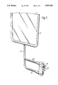
- FIG. 1 is a perspective view of an exterior rear view mirror in accordance with the invention, in which the support elements take the form of laterally projecting arms;
- FIG. 2 is a sectional view of the pivot joint connecting the arms to the bracket of the embodiment shown in FIG. 1;
- FIG. 3 is an exploded perspective view illustrating the detent formations of the embodiment shown in FIGS. 1 and 2.
- a mirror assembly comprises a mirror housing 10 containing a reflective member 12 mounted on the vertical limb 14 of an L-shaped member, the horizontal limb of which forms a lower arm 16 which is pivotally connected to the bottom of a bracket 18.
- the bracket 18 has a face 20 intended to abut against a vehicle body (not shown).
- An upper arm 22 has one end pivotally connected to the top of the bracket 18 and the other end welded onto the vertical limb 14 of the L-shaped member.
- the end 24 of the upper arm 22 connected to the bracket 18 is flattened and contains a hole 26.
- the corresponding end 28 of the lower arm 16 is similarly flattened and contains a hole 30.
- the upper surface of the bracket 18 contains a hole 32 which extends into an enlarged cylindrical cavity 34, the bottom end of which contains a cylindrical slider 36 having a stub formation 38 which is received in the hole 30 in the end 28 of the lower arm 16.
- a bolt 40 extends through the hole 26 in the upper arm 22, the hole 32 in the top of the bracket 20, the cylindrical cavity 34, a central hole in the slider 36 and the hole 30 in the lower arm 16.
- Respective nuts 42 and 44 on the ends of the bolt 40 hold washers 46 and 48 in engagement with the flattened ends 24 and 28 of the arms 22 and 16 respectively.
- a compression spring 50 engages between the top of the cylindrical cavity 34 and the top of the slider 36 so as to urge the arms 16 and 22 downwardly relative to the bracket 20.
- a washer 60 is located between the lower surface 62 of the flattened end portion 24 of the upper arm 22 and the top surface 64 of the bracket 18.
- a pair of detent formations 66 and 68 are located on the surface 64 at diametrically spaced locations around the hole 32.
- the formations 66 and 68 have sloping side surfaces and engage in correspondingly shaped grooves 70 and 72 in the bottom surface of the washer 60.
- the washer 60 has a pair of diametrically spaced grooves 74 and 76, of rectangular cross-section, in its top surface, orientated at 90° to the grooves 70 and 72 in its bottom surface.
- the lower surface 62 of the flattened end portion 24 of the upper arm 22 carries a pair of downwardly projecting lugs 78 and 80 which engage in the grooves 74 and 76 respectively.
- the projections 66 and 68 ride up the sloping side walls of the grooves 72 and 74, compressing the spring 50.
- the lugs 78 and 80 remain in engagement with the rectangular slots 74 and 76. Consequently, when the arms 16 and 22 are moved back to their preferred orientation, the lugs 78 and 80 move the washer 60 back to the correct orientation for the detent formations 66 and 68 to re-engage.
Abstract
Description
Claims (4)
Applications Claiming Priority (2)
| Application Number | Priority Date | Filing Date | Title |
|---|---|---|---|
| GB8916831 | 1989-07-22 | ||
| GB898916831A GB8916831D0 (en) | 1989-07-22 | 1989-07-22 | Vehicle exterior mirror |
Publications (1)
| Publication Number | Publication Date |
|---|---|
| US5081546A true US5081546A (en) | 1992-01-14 |
Family
ID=10660503
Family Applications (1)
| Application Number | Title | Priority Date | Filing Date |
|---|---|---|---|
| US07/556,296 Expired - Fee Related US5081546A (en) | 1989-07-22 | 1990-07-20 | Vehicle exterior mirror |
Country Status (5)
| Country | Link |
|---|---|
| US (1) | US5081546A (en) |
| EP (1) | EP0410587B1 (en) |
| BR (1) | BR9003507A (en) |
| DE (1) | DE69003325T2 (en) |
| GB (1) | GB8916831D0 (en) |
Cited By (27)
| Publication number | Priority date | Publication date | Assignee | Title |
|---|---|---|---|---|
| US5292100A (en) * | 1993-04-16 | 1994-03-08 | Byers Gary L | Adjustable support for vehicle side view mirror |
| US5722629A (en) * | 1994-08-20 | 1998-03-03 | Mekra Rangau Plastics Gmbh & Co. Kg | Mounting for an external rear view mirror of commercial vehicles |
| US5798879A (en) * | 1995-06-07 | 1998-08-25 | Salvio; Paul R. | Stress-free, adjustable optical support |
| US5841594A (en) * | 1996-09-27 | 1998-11-24 | Britax Rainsfords Pty Ltd. | Pivot connection |
| US6276805B1 (en) | 1999-09-17 | 2001-08-21 | Paul Home | Trailer tow mirror |
| US6286968B1 (en) * | 1999-09-07 | 2001-09-11 | Lang-Mekra North America, Llc | Mirror mounting assembly with stop feature |
| US6369702B1 (en) | 1999-02-05 | 2002-04-09 | Lang-Mekra North America, Llc | Rearview mirror with safety catch |
| US6371618B1 (en) * | 1996-01-16 | 2002-04-16 | Rosco Inc. | Single shell, double view vehicular mirror having manual adjustability and precision hinge plate |
| US6371620B1 (en) | 1999-11-23 | 2002-04-16 | Lang-Mekra North America, Llc | Outside mirror with quick assembly |
| US6390631B1 (en) | 1999-02-05 | 2002-05-21 | Lang-Mekra North America, Llc | System for automatic adjustment of external mirrors for motor vehicles when driving in curves |
| US6416191B1 (en) | 1999-03-23 | 2002-07-09 | Lang-Mekra North America, Llc | Double walled carrier plate and related mirror assembly |
| US6555222B1 (en) | 2000-01-13 | 2003-04-29 | Schefenacker Vision Systems France Sa | Reinforced polypropylene mirror assembly and process for making the same |
| US20040051983A1 (en) * | 2002-08-29 | 2004-03-18 | Heinrich Lang | Outside rear view mirror for commercial vehicles |
| US6814336B2 (en) | 2002-08-23 | 2004-11-09 | Lang-Mekra North America, Llc | Key system for a mirror assembly |
| US6830352B2 (en) | 2000-12-22 | 2004-12-14 | Lang Mekra North America, Llc | Rearview mirror assembly for motor vehicles |
| US20050213232A1 (en) * | 2002-02-25 | 2005-09-29 | Rosco, Inc. | Retractable rear view mirror |
| US6962422B1 (en) * | 1996-01-16 | 2005-11-08 | Roscoe, Inc. | Single shell, double view mirror for vehicles |
| US20060109572A1 (en) * | 2004-11-24 | 2006-05-25 | Mirror Lite | Mirror a-pillar mounting bracket assembly |
| US20070053087A1 (en) * | 2001-03-06 | 2007-03-08 | Emmanuel Courbon | Rearview mirror assembly for motor vehicles |
| US20070211356A1 (en) * | 2006-03-07 | 2007-09-13 | Brester Robert R | Mirror with adjustable detent |
| US7290741B1 (en) * | 2004-11-01 | 2007-11-06 | Jacob Holtz Company | Furniture glide |
| US7497580B2 (en) | 2001-10-02 | 2009-03-03 | Lang Mekra North America, Llc | Apparatus for pivoting a mirror assembly |
| US20090166505A1 (en) * | 2008-01-02 | 2009-07-02 | Emmanuel Courbon | Multi-axis pivoting detent joint assembly for an exterior vehicle mirror |
| EP2077205A2 (en) | 2008-01-02 | 2009-07-08 | MEKRA Lang GmbH & Co. KG | A multi-axis pivoting detent joint assembly for an exterior vehicle mirror |
| EP2110283A1 (en) | 2008-04-17 | 2009-10-21 | MEKRA Lang GmbH & Co. KG | Pivoting Detent Joint |
| US7631977B2 (en) * | 1999-01-13 | 2009-12-15 | Lang Mekra North America, Llc | Lockable rearview mirror assembly |
| US11142127B2 (en) * | 2017-05-24 | 2021-10-12 | SMR Patents S.à.r.l. | Pivot joint system and rear view device therewith |
Families Citing this family (4)
| Publication number | Priority date | Publication date | Assignee | Title |
|---|---|---|---|---|
| IT216986Z2 (en) * | 1989-03-20 | 1991-10-21 | Gilardini Spa | HINGE GROUP FOR A SUPPORT ELEMENT OF A REAR VIEW GROUP FOR AN EXTERNAL VEHICLE |
| US5342015A (en) * | 1993-05-11 | 1994-08-30 | Steven Brownlee | Apparatus for mounting rear view mirrors on a tractor |
| GB2281543B (en) * | 1993-09-04 | 1996-10-02 | Raydyot Ltd | Mirror mechanisms |
| GB2374578A (en) * | 2001-04-17 | 2002-10-23 | Emmanuel Courbon | A parking mechanism for a vehicle mirror |
Citations (11)
| Publication number | Priority date | Publication date | Assignee | Title |
|---|---|---|---|---|
| GB191113402A (en) * | 1911-06-03 | 1912-02-22 | Harry Lucas | Improvements relating to Reflector Attachments for use particularly on Cycles, Motor Cycles and the like. |
| US3339876A (en) * | 1964-06-29 | 1967-09-05 | J W Speaker Corp | Side mount rear view truck mirror |
| US3346229A (en) * | 1964-06-17 | 1967-10-10 | Velvac Inc | Vehicle mirror assembly |
| US3384334A (en) * | 1966-01-20 | 1968-05-21 | Yankee Metal Products Corp | Mirror support |
| US3433511A (en) * | 1966-11-21 | 1969-03-18 | Allen Elect Equip | Joint for outside rear view mirrors |
| DE1500767A1 (en) * | 1965-05-13 | 1969-08-07 | Homerton Engineering Ltd | Bracket, e.g. for the sun visor in a motor vehicle |
| US3784149A (en) * | 1972-01-03 | 1974-01-08 | Dominion Auto Access | Retractable truck mirror |
| US4523735A (en) * | 1984-01-30 | 1985-06-18 | Delbar Products, Inc. | Mirror swing lock mechanism |
| US4623115A (en) * | 1985-11-12 | 1986-11-18 | Velvac, Inc. | Preset mirror mount |
| EP0221255A2 (en) * | 1985-11-06 | 1987-05-13 | Hagus C. Luchtenberg GmbH & Co. KG | Vehicle rear view mirror |
| US4852970A (en) * | 1988-01-21 | 1989-08-01 | Kitrell John V | Visual signal device for a bicycle |
Family Cites Families (4)
| Publication number | Priority date | Publication date | Assignee | Title |
|---|---|---|---|---|
| GB1044921A (en) * | 1964-02-03 | 1966-10-05 | John Ross Newby | Hinged joint support, as for a rear view mirror mounting |
| US4218036A (en) * | 1978-08-28 | 1980-08-19 | Re-Trac Corporation | Bracket for mounting a rear view mirror on a vehicle |
| GB2049586B (en) * | 1979-02-20 | 1983-01-12 | Surrey Steel Components Ltd | Base for vehicle rear view mirror |
| US4363534A (en) * | 1979-10-05 | 1982-12-14 | Covert Stanley R | Retractable mirror and lock therefor |
-
1989
- 1989-07-22 GB GB898916831A patent/GB8916831D0/en active Pending
-
1990
- 1990-07-02 DE DE90307215T patent/DE69003325T2/en not_active Expired - Fee Related
- 1990-07-02 EP EP90307215A patent/EP0410587B1/en not_active Expired - Lifetime
- 1990-07-19 BR BR909003507A patent/BR9003507A/en not_active IP Right Cessation
- 1990-07-20 US US07/556,296 patent/US5081546A/en not_active Expired - Fee Related
Patent Citations (11)
| Publication number | Priority date | Publication date | Assignee | Title |
|---|---|---|---|---|
| GB191113402A (en) * | 1911-06-03 | 1912-02-22 | Harry Lucas | Improvements relating to Reflector Attachments for use particularly on Cycles, Motor Cycles and the like. |
| US3346229A (en) * | 1964-06-17 | 1967-10-10 | Velvac Inc | Vehicle mirror assembly |
| US3339876A (en) * | 1964-06-29 | 1967-09-05 | J W Speaker Corp | Side mount rear view truck mirror |
| DE1500767A1 (en) * | 1965-05-13 | 1969-08-07 | Homerton Engineering Ltd | Bracket, e.g. for the sun visor in a motor vehicle |
| US3384334A (en) * | 1966-01-20 | 1968-05-21 | Yankee Metal Products Corp | Mirror support |
| US3433511A (en) * | 1966-11-21 | 1969-03-18 | Allen Elect Equip | Joint for outside rear view mirrors |
| US3784149A (en) * | 1972-01-03 | 1974-01-08 | Dominion Auto Access | Retractable truck mirror |
| US4523735A (en) * | 1984-01-30 | 1985-06-18 | Delbar Products, Inc. | Mirror swing lock mechanism |
| EP0221255A2 (en) * | 1985-11-06 | 1987-05-13 | Hagus C. Luchtenberg GmbH & Co. KG | Vehicle rear view mirror |
| US4623115A (en) * | 1985-11-12 | 1986-11-18 | Velvac, Inc. | Preset mirror mount |
| US4852970A (en) * | 1988-01-21 | 1989-08-01 | Kitrell John V | Visual signal device for a bicycle |
Cited By (40)
| Publication number | Priority date | Publication date | Assignee | Title |
|---|---|---|---|---|
| US5292100A (en) * | 1993-04-16 | 1994-03-08 | Byers Gary L | Adjustable support for vehicle side view mirror |
| US5722629A (en) * | 1994-08-20 | 1998-03-03 | Mekra Rangau Plastics Gmbh & Co. Kg | Mounting for an external rear view mirror of commercial vehicles |
| US5798879A (en) * | 1995-06-07 | 1998-08-25 | Salvio; Paul R. | Stress-free, adjustable optical support |
| US6962422B1 (en) * | 1996-01-16 | 2005-11-08 | Roscoe, Inc. | Single shell, double view mirror for vehicles |
| US6371618B1 (en) * | 1996-01-16 | 2002-04-16 | Rosco Inc. | Single shell, double view vehicular mirror having manual adjustability and precision hinge plate |
| US5841594A (en) * | 1996-09-27 | 1998-11-24 | Britax Rainsfords Pty Ltd. | Pivot connection |
| US7631977B2 (en) * | 1999-01-13 | 2009-12-15 | Lang Mekra North America, Llc | Lockable rearview mirror assembly |
| US6369702B1 (en) | 1999-02-05 | 2002-04-09 | Lang-Mekra North America, Llc | Rearview mirror with safety catch |
| US6390631B1 (en) | 1999-02-05 | 2002-05-21 | Lang-Mekra North America, Llc | System for automatic adjustment of external mirrors for motor vehicles when driving in curves |
| US6416191B1 (en) | 1999-03-23 | 2002-07-09 | Lang-Mekra North America, Llc | Double walled carrier plate and related mirror assembly |
| US6286968B1 (en) * | 1999-09-07 | 2001-09-11 | Lang-Mekra North America, Llc | Mirror mounting assembly with stop feature |
| US6276805B1 (en) | 1999-09-17 | 2001-08-21 | Paul Home | Trailer tow mirror |
| US6416192B2 (en) | 1999-09-17 | 2002-07-09 | Paul Home | Trailer tow mirror |
| US6592231B2 (en) | 1999-09-17 | 2003-07-15 | Paul Home | Trailer tow mirror |
| US6896379B2 (en) | 1999-09-17 | 2005-05-24 | Britax Rainsfords Pty. Limited | Trailer tow mirror |
| US20090135509A1 (en) * | 1999-11-23 | 2009-05-28 | Rosco Inc. | Retractable rear view mirror |
| US7959309B2 (en) | 1999-11-23 | 2011-06-14 | Rosco Inc. | Retractable rear view mirror |
| US6371620B1 (en) | 1999-11-23 | 2002-04-16 | Lang-Mekra North America, Llc | Outside mirror with quick assembly |
| US6555222B1 (en) | 2000-01-13 | 2003-04-29 | Schefenacker Vision Systems France Sa | Reinforced polypropylene mirror assembly and process for making the same |
| US6830352B2 (en) | 2000-12-22 | 2004-12-14 | Lang Mekra North America, Llc | Rearview mirror assembly for motor vehicles |
| US20070053087A1 (en) * | 2001-03-06 | 2007-03-08 | Emmanuel Courbon | Rearview mirror assembly for motor vehicles |
| US7357522B2 (en) | 2001-03-06 | 2008-04-15 | Lang Mekra North America, Llc | Rearview mirror assembly for motor vehicles |
| US7497580B2 (en) | 2001-10-02 | 2009-03-03 | Lang Mekra North America, Llc | Apparatus for pivoting a mirror assembly |
| US20050213232A1 (en) * | 2002-02-25 | 2005-09-29 | Rosco, Inc. | Retractable rear view mirror |
| US7455413B2 (en) * | 2002-02-25 | 2008-11-25 | Rosco, Inc. | Retractable rearview mirror including a rebounding mechanism |
| US6814336B2 (en) | 2002-08-23 | 2004-11-09 | Lang-Mekra North America, Llc | Key system for a mirror assembly |
| US20040051983A1 (en) * | 2002-08-29 | 2004-03-18 | Heinrich Lang | Outside rear view mirror for commercial vehicles |
| US7113340B2 (en) | 2002-08-29 | 2006-09-26 | Lang-Mekra North America, Llc | Outside rear view mirror for commercial vehicles |
| US7290741B1 (en) * | 2004-11-01 | 2007-11-06 | Jacob Holtz Company | Furniture glide |
| US20060109572A1 (en) * | 2004-11-24 | 2006-05-25 | Mirror Lite | Mirror a-pillar mounting bracket assembly |
| US7452088B2 (en) * | 2006-03-07 | 2008-11-18 | Velvac, Incorporated | Mirror with adjustable detent |
| US20070211356A1 (en) * | 2006-03-07 | 2007-09-13 | Brester Robert R | Mirror with adjustable detent |
| US20090166505A1 (en) * | 2008-01-02 | 2009-07-02 | Emmanuel Courbon | Multi-axis pivoting detent joint assembly for an exterior vehicle mirror |
| EP2077205A2 (en) | 2008-01-02 | 2009-07-08 | MEKRA Lang GmbH & Co. KG | A multi-axis pivoting detent joint assembly for an exterior vehicle mirror |
| EP2077205A3 (en) * | 2008-01-02 | 2009-11-04 | MEKRA Lang GmbH & Co. KG | A multi-axis pivoting detent joint assembly for an exterior vehicle mirror |
| US7878477B2 (en) | 2008-01-02 | 2011-02-01 | Lang-Mekra North America, Llc | Multi-axis pivoting detent joint assembly for an exterior vehicle mirror |
| EP2110283A1 (en) | 2008-04-17 | 2009-10-21 | MEKRA Lang GmbH & Co. KG | Pivoting Detent Joint |
| US20090261226A1 (en) * | 2008-04-17 | 2009-10-22 | Michael Dean Branham | Pivoting detent joint |
| US7686274B2 (en) | 2008-04-17 | 2010-03-30 | Lang-Mekra North America Llc | Pivoting detent joint |
| US11142127B2 (en) * | 2017-05-24 | 2021-10-12 | SMR Patents S.à.r.l. | Pivot joint system and rear view device therewith |
Also Published As
| Publication number | Publication date |
|---|---|
| EP0410587B1 (en) | 1993-09-15 |
| DE69003325D1 (en) | 1993-10-21 |
| GB8916831D0 (en) | 1989-09-06 |
| EP0410587A2 (en) | 1991-01-30 |
| DE69003325T2 (en) | 1994-03-31 |
| EP0410587A3 (en) | 1991-11-21 |
| BR9003507A (en) | 1991-08-27 |
Similar Documents
| Publication | Publication Date | Title |
|---|---|---|
| US5081546A (en) | Vehicle exterior mirror | |
| US4501045A (en) | Self-locking hinge | |
| EP0272047B1 (en) | A pivotable screw jack drive | |
| US5137247A (en) | Holding device for an external rear-view mirror for a commercial vehicle | |
| EP0203456A2 (en) | Electric control mirror apparatus | |
| JPS5984642A (en) | Shock absorber of door mirror for automobile | |
| EP0511203A1 (en) | Automotive rearview mirror assembly. | |
| JP2006321482A (en) | Conical support arm joint for vehicle mirror | |
| JPS6294445A (en) | Back mirror for automobile | |
| US5363245A (en) | Vehicle rearview mirror | |
| KR910007134B1 (en) | Rear-view mirror | |
| CA1304246C (en) | Breakaway mirrors | |
| US4988068A (en) | Remote control mechanism | |
| ES288597U (en) | Exterior rearview mirrors for vehicles. | |
| US4651965A (en) | External rear-view mirror for motor vehicles | |
| US4613107A (en) | External rearview mirror for motor vehicles, which can be used selectively in an upright position and in a laterally-projecting position | |
| EP0747612B1 (en) | Gear change device for a transmission | |
| US4830327A (en) | Rear vision mirror adjusting means | |
| JPS632752A (en) | External back mirror for motor vehicle | |
| US6769781B2 (en) | Remote control mirror apparatus for automobile | |
| EP0064335B1 (en) | Rear-view mirror for motor vehicles | |
| EP0074753B1 (en) | Rear-view mirror for motor vehicles | |
| GB1578950A (en) | Rear view mirror assembly | |
| GB2128564A (en) | Vehicle rear-view mirror assembly | |
| EP0110600B1 (en) | Rear view mirror assembly |
Legal Events
| Date | Code | Title | Description |
|---|---|---|---|
| AS | Assignment |
Owner name: BRITAX WINGARD LIMITED, KINGSHAM ROAD, CHICHESTER, Free format text: ASSIGNMENT OF ASSIGNORS INTEREST.;ASSIGNOR:BOTTRILL, JOHN;REEL/FRAME:005378/0967 Effective date: 19900530 |
|
| FEPP | Fee payment procedure |
Free format text: PAYOR NUMBER ASSIGNED (ORIGINAL EVENT CODE: ASPN); ENTITY STATUS OF PATENT OWNER: LARGE ENTITY |
|
| CC | Certificate of correction | ||
| AS | Assignment |
Owner name: BRITAX WINGARD LIMITED, ENGLAND Free format text: CHANGE OF NAME;ASSIGNORS:BRITAX (WINGARD) LIMITED;WINGARD LIMITED;REEL/FRAME:006752/0548 Effective date: 19921109 |
|
| FPAY | Fee payment |
Year of fee payment: 4 |
|
| FPAY | Fee payment |
Year of fee payment: 8 |
|
| REMI | Maintenance fee reminder mailed | ||
| LAPS | Lapse for failure to pay maintenance fees | ||
| STCH | Information on status: patent discontinuation |
Free format text: PATENT EXPIRED DUE TO NONPAYMENT OF MAINTENANCE FEES UNDER 37 CFR 1.362 |
|
| FP | Lapsed due to failure to pay maintenance fee |
Effective date: 20040114 |