US5081866A - Respiratory air flowmeter - Google Patents
Respiratory air flowmeter Download PDFInfo
- Publication number
- US5081866A US5081866A US07/530,237 US53023790A US5081866A US 5081866 A US5081866 A US 5081866A US 53023790 A US53023790 A US 53023790A US 5081866 A US5081866 A US 5081866A
- Authority
- US
- United States
- Prior art keywords
- respiratory air
- sensor
- flow
- flow path
- segment
- Prior art date
- Legal status (The legal status is an assumption and is not a legal conclusion. Google has not performed a legal analysis and makes no representation as to the accuracy of the status listed.)
- Expired - Lifetime
Links
Images

Classifications
-
- A—HUMAN NECESSITIES
- A61—MEDICAL OR VETERINARY SCIENCE; HYGIENE
- A61B—DIAGNOSIS; SURGERY; IDENTIFICATION
- A61B5/00—Measuring for diagnostic purposes; Identification of persons
- A61B5/08—Detecting, measuring or recording devices for evaluating the respiratory organs
- A61B5/087—Measuring breath flow
- A61B5/0878—Measuring breath flow using temperature sensing means
-
- G—PHYSICS
- G01—MEASURING; TESTING
- G01F—MEASURING VOLUME, VOLUME FLOW, MASS FLOW OR LIQUID LEVEL; METERING BY VOLUME
- G01F1/00—Measuring the volume flow or mass flow of fluid or fluent solid material wherein the fluid passes through a meter in a continuous flow
- G01F1/68—Measuring the volume flow or mass flow of fluid or fluent solid material wherein the fluid passes through a meter in a continuous flow by using thermal effects
- G01F1/684—Structural arrangements; Mounting of elements, e.g. in relation to fluid flow
- G01F1/6842—Structural arrangements; Mounting of elements, e.g. in relation to fluid flow with means for influencing the fluid flow
-
- G—PHYSICS
- G01—MEASURING; TESTING
- G01F—MEASURING VOLUME, VOLUME FLOW, MASS FLOW OR LIQUID LEVEL; METERING BY VOLUME
- G01F1/00—Measuring the volume flow or mass flow of fluid or fluent solid material wherein the fluid passes through a meter in a continuous flow
- G01F1/68—Measuring the volume flow or mass flow of fluid or fluent solid material wherein the fluid passes through a meter in a continuous flow by using thermal effects
- G01F1/684—Structural arrangements; Mounting of elements, e.g. in relation to fluid flow
- G01F1/6845—Micromachined devices
-
- G—PHYSICS
- G01—MEASURING; TESTING
- G01F—MEASURING VOLUME, VOLUME FLOW, MASS FLOW OR LIQUID LEVEL; METERING BY VOLUME
- G01F15/00—Details of, or accessories for, apparatus of groups G01F1/00 - G01F13/00 insofar as such details or appliances are not adapted to particular types of such apparatus
Definitions
- the present invention relates to a respiratory air flowmeter used for medical applications.
- Various conventional clinical methods of measuring the flow rate of respiratory air of a patient are known, e.g., (1) a method of using a resistance tube, (2) a method of using a hot-wire anemometer, (3) a method of using a variable orifice, and (4) a method of using a body plethysmograph.
- a tube having a resistance arranged midway along its tube path is inserted in a patient, and the flow rate of respiratory air of the patient is measured on the basis of a difference between pressures before and after the resistance.
- the overall tube is heavy and is difficult to be mounted in the patient.
- the tube is expensive.
- the tube must be cleaned every time it is used and requires a cumbersome handling.
- the tube cannot correctly respond as the speed of respiration is increased.
- various disadvantages are posed, e.g., requiring a large, expensive apparatus, calibration for every measurement, difficult handling, special care in measurement of a reciprocating flow, and dangerous for a patient when the hot-wire is disconnected.
- the method of using a variable orifice is advantageous in that it has a simple structure.
- it has a critical disadvantage, i.e., low precision.
- a patient enters a box having a volume of about 500 l, and the flow rate of respiratory air is measured on the basis of a change in volume or pressure caused by respiration. This requires a large, expensive apparatus.
- temperatures, atmospheric pressures, and the like must be corrected, and the patient must be moved, measurement cannot be easily performed.
- an object of the present invention to solve the conventional problems described above and provide a small, light respiratory air flowmeter which is easy to handle, causes little suffering to a patient, can be provided at low cost so as to be disposable, and can respond to a change from a forward flow to a reverse flow at high speed.
- a respiratory air flowmeter comprising a flow path forming member for forming a flow path in which respiratory air flows, a restricting portion and a rectifying lattice, arranged in the flow path, for stabilizing a respiratory air flow, and a sensor, mounted in a sensor mounting portion of the flow path forming member, for detecting a flow rate of respiratory air flowing in the flow path.
- the respiratory air when respiratory air flows in the flow path of the flow path forming member, the respiratory air is rectified by the rectifying lattice and the restricting portion and becomes a stable flow.
- the sensor When the stable flow is brought into contact with the sensor, the sensor outputs a stable signal upon detection of the flow.
- the detection signal is processed by a processor, the flow rate of the respiratory air is measured.
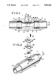
- FIG. 1 is a sectional view showing a respiratory air flowmeter according to an embodiment of the present invention
- FIG. 2 is an exploded perspective view of the respiratory air flowmeter
- FIG. 3 is a sectional view showing a main part of the respiratory air flowmeter.
- FIG. 4 is a perspective view of a sensor.
- FIGS. 1 to 3 show a respiratory air flowmeter according to an embodiment of the present invention.
- FIG. 4 shows a sensor.
- a respiratory air flowmeter denoted by reference symbol 1 as a whole includes a cylindrical flow path forming member 4 for forming a flow path 3 in which respiratory air 2 is supplied.
- Couplings 5 and 6 having tapered outer and inner surfaces are fitted/fixed in the respective openings of the flow path forming member 4.
- a middle portion of the member 4 is reduced in inner diameter to form a restricting portion 7 for stabilizing the flow of the respiratory air 2.
- a plurality of rectifying lattices 8 for stabilizing the flow of the respiratory air 2 are respectively arranged between the restricting portion 7 and the couplings 5 and 6 through rectifying lattice stop rings 9.
- a recess as a sensor mounting portion 10 in which a sensor 11 is mounted is formed in a middle portion of the outer surface of the flow path forming member 4 in the longitudinal direction.
- a recess as a sensor board seat surface 12 (FIG. 3) is formed in a central portion of the bottom of the sensor mounting portion 10 together with a sensor window 13 for causing the flow path 3 to communicate with the sensor mounting portion 10.
- the board seat surface 12 is formed to be in contact with an inner wall 14 of the flow path 3.
- the sensor 11 constitutes a microsensor, and includes a silicon substrate 16 having a predetermined thickness and size (e.g., 1.7 mm sq and 0.25 mm thick), as shown in FIG. 4.
- a recess portion 18 having a silicon nitride bridge 17 is formed in a central portion of the upper surface of the silicon substrate 16.
- a heater 19 and upstream and downstream temperature sensors 20 and 21 are formed on the bridge 17. These sensors 20 and 21 are formed on both the sides of the heater 19.
- An ambient temperature sensor 22 for measuring an ambient temperature is formed on a portion of the surface of the silicon substrate 16 which does not constitute the bridge 17. With this arrangement, the heater 19 is controlled to have a temperature higher than an ambient temperature by a predetermined degree.
- the sensor 11 having such an arrangement is arranged on a central portion of one surface of a sensor board 15 (FIG. 3) made of a ceramic material or the like and having a size of, e.g., 11 ⁇ 12 ⁇ 0.635 mm.
- a plurality of pins 23 as connectors extend from the other surface of the sensor board 15 opposite the sensor 11 side. These pins 23 are electrically connected to the sensor 11 via through holes (not shown) formed in the sensor board 15.
- the sensor board 15 is arranged on the board seat surface 12 with the sensor 11 facing the flow path 3 through the sensor window 13, thus tightly sealing the sensor window 13.
- a lid 24 is arranged in the sensor mounting portion 10 through a gasket 25 in order to urge/fix the sensor board 15 and seal the sensor window 13.
- These members 24 and 25 are urged/fixed to the bottom of the sensor mounting portion 10, i.e., a gasket seat surface 27 (FIG. 3) with a plurality of set screws 26 (FIG. 2).
- the distance from the gasket seat surface 27 to the board seat surface 12 is smaller than the thickness of the sensor board 15.
- the sensor board 15 slightly protrudes upward from the gasket seat surface 27. This allows sealing of the sensor board 15.
- the lid 24 and the gasket 25 respectively have holes 29 and 30 in their central portions. The holes 29 and 30 are large enough to allow the pins 23 to be inserted.
- a connector 32 attached to one end of a cord 31 (FIG. 1) is connected to the pins 23.
- the other end of the cord 31 is connected to a processor (not shown) for processing a signal from the sensor 11.
- the respiratory air flowmeter 1 having such an arrangement, when the respiratory air 2 is supplied into the flow path 3 through the coupling 5, the air is rectified by the rectifying lattices 8. The air is further rectified by the restricting portion 7 to be formed into a stable flow, and the air is brought into contact with the sensor 11.
- the respiratory air 2 is brought into contact with the sensor 11, temperature distributions on both the sides of the heater 19 are offset from each other.
- this offset is detected by the upstream and downstream temperature sensors 20 and 21 on both the sides of the heater 19, it is detected that the respiratory air 2 is flowing.
- the detection signals from these sensor 20 and 21 are supplied to the processor through the cord 31 and are electrically processed, thereby measuring the flow rate of the respiratory air 2.
- the bridge 17 of the sensor 11 is not in contact with the silicon substrate 16, the heat capacity of the sensor 11 is small. This allows the sensor 11 to have a high response speed.
- the two temperature sensors 20 and 21 are used, forward and reverse flows of air can be discriminated by determining which sensor detects a higher temperature.
- an air flow formed in expiration is defined to be a forward flow, and a temperature detected by the upstream temperature sensor in expiration is lower than that detected by the downstream temperature sensor, and vice versa in inspiration.
- the sensor window 13 is air-tightly sealed by using the gasket 25, the lid 24, and the set screws 26.
- the sensor window 13 can be satisfactorily sealed by fixing the sensor board 15 to the board seat surface 12 using only an adhesive tape having the same shape as that of the gasket 25.
- the lid 24 and the set screws 26 are not required, the respiratory air flowmeter can be simplified and reduced in diameter.
- the number of rectifying lattices 8 to be arranged in the flow path 3 can be decreased. This enables a reduction in length of the flow path 3.
- the respiratory air flowmeter of the present invention since the rectifying lattices and the restricting portion are arranged in the flow path, respiratory air flowing in the flow path can be guided to the sensor while it is stabilized. This allows high-precision measurement of the flow rate of respiratory air.
- the restricting portion is formed and only the sensor and the rectifying lattices are arranged in the flow path, the respiratory air flowmeter can be greatly simplified in structure and reduced in size and weight. Therefore, even if the flowmeter is attached to the mouth of a patient, he/she suffers little torment.
- the respiratory air flowmeter can be safely used not only as a medical flowmeter but also as a general flowmeter. If a microsensor is used as the sensor, a change from a forward flow to a reverse flow can be detected at high speed.
- the respiratory air flowmeter of the present invention can be provided at a low cost, it may be used as a disposable flowmeter. This provides great effects, e.g., omission of cumbersome operations after the use of the flowmeter, such as disinfection and sterilization.
Abstract
Description
Claims (9)
Priority Applications (1)
| Application Number | Priority Date | Filing Date | Title |
|---|---|---|---|
| US07/530,237 US5081866A (en) | 1990-05-30 | 1990-05-30 | Respiratory air flowmeter |
Applications Claiming Priority (1)
| Application Number | Priority Date | Filing Date | Title |
|---|---|---|---|
| US07/530,237 US5081866A (en) | 1990-05-30 | 1990-05-30 | Respiratory air flowmeter |
Publications (1)
| Publication Number | Publication Date |
|---|---|
| US5081866A true US5081866A (en) | 1992-01-21 |
Family
ID=24112937
Family Applications (1)
| Application Number | Title | Priority Date | Filing Date |
|---|---|---|---|
| US07/530,237 Expired - Lifetime US5081866A (en) | 1990-05-30 | 1990-05-30 | Respiratory air flowmeter |
Country Status (1)
| Country | Link |
|---|---|
| US (1) | US5081866A (en) |
Cited By (54)
| Publication number | Priority date | Publication date | Assignee | Title |
|---|---|---|---|---|
| US5220830A (en) * | 1991-07-09 | 1993-06-22 | Honeywell Inc. | Compact gas flow meter using electronic microsensors |
| US5558099A (en) * | 1991-03-05 | 1996-09-24 | Edentec, Inc. | Flow sensor system |
| US5573004A (en) * | 1994-10-06 | 1996-11-12 | Edentec Corporation | Electrically stable electrode and sensor apparatus |
| US5581027A (en) * | 1993-12-23 | 1996-12-03 | Honeywell Inc. | Dual integral ballast flow sensor |
| US5596969A (en) * | 1995-10-02 | 1997-01-28 | Cummins Engine Company, Inc. | Flow conditioning gas mass sensor |
| US5676132A (en) * | 1995-12-05 | 1997-10-14 | Pulmonary Interface, Inc. | Pulmonary interface system |
| WO1998012509A1 (en) * | 1996-09-16 | 1998-03-26 | Robert Bosch Gmbh | Device for measuring the mass of a flowing medium |
| EP0994332A1 (en) * | 1998-10-16 | 2000-04-19 | Mannesmann VDO Aktiengesellschaft | Air mass flow meter |
| US6112590A (en) * | 1996-12-18 | 2000-09-05 | Robert Bosch Gmbh | Device for measuring the mass of a fluid element |
| DE19934398A1 (en) * | 1999-07-22 | 2001-02-08 | Horst Jungkeit | Mass flow measurement and control appts consists of a block construction with flat building elements with one or two channels, and integral instruments. |
| US6240775B1 (en) * | 1998-05-11 | 2001-06-05 | Mitsubishi Denki Kabushiki Kaisha | Flow rate sensor |
| EP1128167A1 (en) * | 1998-08-18 | 2001-08-29 | Mitsui Mining & Smelting Co., Ltd. | Flow sensor and strainer integrated flowmeter |
| WO2001084087A1 (en) * | 2000-05-04 | 2001-11-08 | Sensirion Ag | Flow sensor |
| US6322247B1 (en) * | 1999-01-28 | 2001-11-27 | Honeywell International Inc. | Microsensor housing |
| US6361206B1 (en) * | 1999-01-28 | 2002-03-26 | Honeywell International Inc. | Microsensor housing |
| US20030107467A1 (en) * | 1998-12-07 | 2003-06-12 | Ulrich Bonne | Sensor package for harsh environments |
| EP1374940A2 (en) | 1997-06-17 | 2004-01-02 | Fisher & Paykel Healthcare Limited | Respiratory humidification system |
| US6779712B2 (en) | 2002-04-03 | 2004-08-24 | Sensirion Ag | Flow sensor and method for producing the same |
| EP1499860A1 (en) * | 2002-06-28 | 2005-01-26 | Heetronix | Mass flow meter with chip-type sensors |
| US20050022594A1 (en) * | 1998-12-07 | 2005-02-03 | Aravind Padmanabhan | Flow sensor with self-aligned flow channel |
| US20050105243A1 (en) * | 2003-11-17 | 2005-05-19 | Samsung Electronics Co., Ltd | Electrostatic chuck for supporting a substrate |
| US20050268712A1 (en) * | 2004-06-08 | 2005-12-08 | Honeywell International, Inc. | Disposable fluid flow sensor |
| US7168334B1 (en) * | 2000-05-30 | 2007-01-30 | Gambro Lundia Ab | Arrangement for measuring a property of a fluid present in a tube |
| US20070044573A1 (en) * | 2005-08-26 | 2007-03-01 | Smc Kabushiki Kaisha | Flow Meter |
| US20070068246A1 (en) * | 2005-09-29 | 2007-03-29 | Mitsubishi Denki Kabushiki Kaisha | Flow rate measuring apparatus |
| US20080006085A1 (en) * | 2006-07-05 | 2008-01-10 | Smc Kabushiki Kaisha | Flow Sensor |
| US20080210001A1 (en) * | 2007-03-01 | 2008-09-04 | Sensirion Ag | Device with flow sensor for handling fluids |
| DE102007044045A1 (en) * | 2007-09-14 | 2008-09-18 | Dräger Medical AG & Co. KG | Spirometer sensor for gas flow determination in respiratory gas hose useful in medicine, especially in treatment of respirator problems has much more uniform streaming profile inside sensor because of two sieves in series |
| WO2009080120A1 (en) * | 2007-12-21 | 2009-07-02 | Norgren Gmbh | Thermal flow sensor with turbulence inducers |
| US20090249869A1 (en) * | 2008-04-04 | 2009-10-08 | Sensirion Ag | Flow detector with a housing |
| CN101897588A (en) * | 2009-05-27 | 2010-12-01 | 霍尼韦尔国际公司 | Multi-dynamic-range sensor |
| CN101983736A (en) * | 2010-08-27 | 2011-03-09 | 深圳市普博科技有限公司 | Device for connecting flow transducer and monitoring device thereof |
| US20110226052A1 (en) * | 2010-03-22 | 2011-09-22 | Honeywell International Inc. | Sensor assembly with hydrophobic filter |
| WO2011148159A1 (en) * | 2010-05-24 | 2011-12-01 | Sheffield Hallam University | Respiration monitoring device |
| CN102620780A (en) * | 2011-12-27 | 2012-08-01 | 郑州炜盛电子科技有限公司 | MEMS (micro-electromechanical system) thermal-type flow sensor |
| US8397586B2 (en) | 2010-03-22 | 2013-03-19 | Honeywell International Inc. | Flow sensor assembly with porous insert |
| DE10393177B4 (en) * | 2002-08-29 | 2013-08-22 | Azbil Corporation | Flow straightener |
| US8656772B2 (en) | 2010-03-22 | 2014-02-25 | Honeywell International Inc. | Flow sensor with pressure output signal |
| US8695417B2 (en) | 2011-01-31 | 2014-04-15 | Honeywell International Inc. | Flow sensor with enhanced flow range capability |
| US8756990B2 (en) | 2010-04-09 | 2014-06-24 | Honeywell International Inc. | Molded flow restrictor |
| US20140261433A1 (en) * | 2004-04-09 | 2014-09-18 | Resmed Limited | Nasal assembly |
| US8911380B1 (en) * | 2009-04-17 | 2014-12-16 | Linshom, L.P. | Respiration monitoring system and method |
| US9003877B2 (en) | 2010-06-15 | 2015-04-14 | Honeywell International Inc. | Flow sensor assembly |
| US9052217B2 (en) | 2012-11-09 | 2015-06-09 | Honeywell International Inc. | Variable scale sensor |
| US9091577B2 (en) | 2011-01-31 | 2015-07-28 | Honeywell International Inc. | Flow sensor assembly with integral bypass channel |
| GB2529451A (en) * | 2014-08-20 | 2016-02-24 | Univ Sheffield Hallam | Respiration monitoring apparatus |
| DE102014112261A1 (en) * | 2014-08-27 | 2016-03-03 | Sensirion Ag | Device for flow measurement |
| US20170074695A1 (en) * | 2014-03-04 | 2017-03-16 | Seleon Gmbh | Sensor Block, Pipe, and Production Method |
| US9612146B2 (en) | 2014-02-07 | 2017-04-04 | Honeywell International, Inc. | Airflow sensor with dust reduction |
| JP2017129391A (en) * | 2016-01-19 | 2017-07-27 | 矢崎エナジーシステム株式会社 | Gas meter |
| CN107110684A (en) * | 2014-12-23 | 2017-08-29 | 恩德斯+豪斯流量技术股份有限公司 | Hot-fluid measuring device |
| US9952079B2 (en) | 2015-07-15 | 2018-04-24 | Honeywell International Inc. | Flow sensor |
| US11604084B2 (en) | 2021-04-15 | 2023-03-14 | Analog Devices, Inc. | Sensor package |
| US11796367B2 (en) | 2021-05-07 | 2023-10-24 | Analog Devices, Inc. | Fluid control system |
Citations (6)
| Publication number | Priority date | Publication date | Assignee | Title |
|---|---|---|---|---|
| US3433069A (en) * | 1965-10-01 | 1969-03-18 | Technology Inc | Mass flowmeter structure |
| US3645133A (en) * | 1970-04-15 | 1972-02-29 | Metrophysics Inc | Electronic spirometer |
| US3800592A (en) * | 1972-01-13 | 1974-04-02 | Westerbeke J Corp | Flowmeter |
| US4363238A (en) * | 1979-08-16 | 1982-12-14 | Franz Willam | Device for measuring the breath of patients |
| US4829818A (en) * | 1983-12-27 | 1989-05-16 | Honeywell Inc. | Flow sensor housing |
| US4972708A (en) * | 1983-01-22 | 1990-11-27 | Leybold Aktiengesellschaft | Thermal mass flow-meter particularly for gases |
-
1990
- 1990-05-30 US US07/530,237 patent/US5081866A/en not_active Expired - Lifetime
Patent Citations (6)
| Publication number | Priority date | Publication date | Assignee | Title |
|---|---|---|---|---|
| US3433069A (en) * | 1965-10-01 | 1969-03-18 | Technology Inc | Mass flowmeter structure |
| US3645133A (en) * | 1970-04-15 | 1972-02-29 | Metrophysics Inc | Electronic spirometer |
| US3800592A (en) * | 1972-01-13 | 1974-04-02 | Westerbeke J Corp | Flowmeter |
| US4363238A (en) * | 1979-08-16 | 1982-12-14 | Franz Willam | Device for measuring the breath of patients |
| US4972708A (en) * | 1983-01-22 | 1990-11-27 | Leybold Aktiengesellschaft | Thermal mass flow-meter particularly for gases |
| US4829818A (en) * | 1983-12-27 | 1989-05-16 | Honeywell Inc. | Flow sensor housing |
Cited By (85)
| Publication number | Priority date | Publication date | Assignee | Title |
|---|---|---|---|---|
| US5558099A (en) * | 1991-03-05 | 1996-09-24 | Edentec, Inc. | Flow sensor system |
| US5832592A (en) * | 1991-03-05 | 1998-11-10 | Edentec, Inc. | Method of making a respiration sensor |
| US5220830A (en) * | 1991-07-09 | 1993-06-22 | Honeywell Inc. | Compact gas flow meter using electronic microsensors |
| US5581027A (en) * | 1993-12-23 | 1996-12-03 | Honeywell Inc. | Dual integral ballast flow sensor |
| US5573004A (en) * | 1994-10-06 | 1996-11-12 | Edentec Corporation | Electrically stable electrode and sensor apparatus |
| US5596969A (en) * | 1995-10-02 | 1997-01-28 | Cummins Engine Company, Inc. | Flow conditioning gas mass sensor |
| US5676132A (en) * | 1995-12-05 | 1997-10-14 | Pulmonary Interface, Inc. | Pulmonary interface system |
| US6276198B1 (en) * | 1996-09-16 | 2001-08-21 | Robert Bosch Gmbh | Device for measuring the mass of a flowing medium |
| WO1998012509A1 (en) * | 1996-09-16 | 1998-03-26 | Robert Bosch Gmbh | Device for measuring the mass of a flowing medium |
| US6112590A (en) * | 1996-12-18 | 2000-09-05 | Robert Bosch Gmbh | Device for measuring the mass of a fluid element |
| EP1374940A2 (en) | 1997-06-17 | 2004-01-02 | Fisher & Paykel Healthcare Limited | Respiratory humidification system |
| US6240775B1 (en) * | 1998-05-11 | 2001-06-05 | Mitsubishi Denki Kabushiki Kaisha | Flow rate sensor |
| EP1128167A4 (en) * | 1998-08-18 | 2006-08-16 | Mitsui Mining & Smelting Co | Flow sensor and strainer integrated flowmeter |
| EP1128167A1 (en) * | 1998-08-18 | 2001-08-29 | Mitsui Mining & Smelting Co., Ltd. | Flow sensor and strainer integrated flowmeter |
| EP0994332A1 (en) * | 1998-10-16 | 2000-04-19 | Mannesmann VDO Aktiengesellschaft | Air mass flow meter |
| DE19847714A1 (en) * | 1998-10-16 | 2000-04-27 | Mannesmann Vdo Ag | Air mass meter |
| US20030107467A1 (en) * | 1998-12-07 | 2003-06-12 | Ulrich Bonne | Sensor package for harsh environments |
| US6911894B2 (en) | 1998-12-07 | 2005-06-28 | Honeywell International Inc. | Sensor package for harsh environments |
| US20080010821A1 (en) * | 1998-12-07 | 2008-01-17 | Honeywell International Inc. | Flow sensor with self-aligned flow channel |
| US7258003B2 (en) | 1998-12-07 | 2007-08-21 | Honeywell International Inc. | Flow sensor with self-aligned flow channel |
| US7793410B2 (en) | 1998-12-07 | 2010-09-14 | Honeywell International Inc. | Method of making a plurality of flow sensors |
| US20050022594A1 (en) * | 1998-12-07 | 2005-02-03 | Aravind Padmanabhan | Flow sensor with self-aligned flow channel |
| US6361206B1 (en) * | 1999-01-28 | 2002-03-26 | Honeywell International Inc. | Microsensor housing |
| US6322247B1 (en) * | 1999-01-28 | 2001-11-27 | Honeywell International Inc. | Microsensor housing |
| DE19934398A1 (en) * | 1999-07-22 | 2001-02-08 | Horst Jungkeit | Mass flow measurement and control appts consists of a block construction with flat building elements with one or two channels, and integral instruments. |
| US6813944B2 (en) | 2000-05-04 | 2004-11-09 | Sensirion Ag | Flow sensor |
| WO2001084087A1 (en) * | 2000-05-04 | 2001-11-08 | Sensirion Ag | Flow sensor |
| US7168334B1 (en) * | 2000-05-30 | 2007-01-30 | Gambro Lundia Ab | Arrangement for measuring a property of a fluid present in a tube |
| US6779712B2 (en) | 2002-04-03 | 2004-08-24 | Sensirion Ag | Flow sensor and method for producing the same |
| WO2003089885A1 (en) * | 2002-04-22 | 2003-10-30 | Honeywell International Inc. | Flow sensor for harsh environments |
| EP1499860A1 (en) * | 2002-06-28 | 2005-01-26 | Heetronix | Mass flow meter with chip-type sensors |
| EP1499860A4 (en) * | 2002-06-28 | 2007-05-30 | Heetronix | Mass flow meter with chip-type sensors |
| DE10393177B4 (en) * | 2002-08-29 | 2013-08-22 | Azbil Corporation | Flow straightener |
| US20050105243A1 (en) * | 2003-11-17 | 2005-05-19 | Samsung Electronics Co., Ltd | Electrostatic chuck for supporting a substrate |
| US9895505B2 (en) * | 2004-04-09 | 2018-02-20 | Resmed Limited | Nasal assembly |
| US10842957B2 (en) | 2004-04-09 | 2020-11-24 | ResMed Pty Ltd | Nasal assembly |
| US20140261433A1 (en) * | 2004-04-09 | 2014-09-18 | Resmed Limited | Nasal assembly |
| WO2005121713A3 (en) * | 2004-06-08 | 2006-06-01 | Honeywell Int Inc | Disposable fluid flow sensor |
| WO2005121713A2 (en) | 2004-06-08 | 2005-12-22 | Honeywell International Inc. | Disposable fluid flow sensor |
| US7096729B2 (en) * | 2004-06-08 | 2006-08-29 | Honeywell International Inc. | Disposable fluid flow sensor |
| US20050268712A1 (en) * | 2004-06-08 | 2005-12-08 | Honeywell International, Inc. | Disposable fluid flow sensor |
| US7415895B2 (en) * | 2005-08-26 | 2008-08-26 | Smc Kabushiki Kaisha | Flow meter with a rectifying module having a plurality of mesh members |
| US20070044573A1 (en) * | 2005-08-26 | 2007-03-01 | Smc Kabushiki Kaisha | Flow Meter |
| US20070068246A1 (en) * | 2005-09-29 | 2007-03-29 | Mitsubishi Denki Kabushiki Kaisha | Flow rate measuring apparatus |
| US7530267B2 (en) * | 2005-09-29 | 2009-05-12 | Mitsubishi Denki Kabushiki Kaisha | Flow rate measuring apparatus |
| US7549332B2 (en) * | 2006-07-05 | 2009-06-23 | Smc Kabushiki Kaisha | Flow sensor and throttle structure |
| US20080006085A1 (en) * | 2006-07-05 | 2008-01-10 | Smc Kabushiki Kaisha | Flow Sensor |
| US20080210001A1 (en) * | 2007-03-01 | 2008-09-04 | Sensirion Ag | Device with flow sensor for handling fluids |
| US7905140B2 (en) | 2007-03-01 | 2011-03-15 | Sensirion Ag | Device with flow sensor for handling fluids |
| DE102007044045A1 (en) * | 2007-09-14 | 2008-09-18 | Dräger Medical AG & Co. KG | Spirometer sensor for gas flow determination in respiratory gas hose useful in medicine, especially in treatment of respirator problems has much more uniform streaming profile inside sensor because of two sieves in series |
| US20100251815A1 (en) * | 2007-12-21 | 2010-10-07 | Norgren Gmbh | Thermal flow sensor with turbulence inducers |
| WO2009080120A1 (en) * | 2007-12-21 | 2009-07-02 | Norgren Gmbh | Thermal flow sensor with turbulence inducers |
| US20090249869A1 (en) * | 2008-04-04 | 2009-10-08 | Sensirion Ag | Flow detector with a housing |
| US7757553B2 (en) | 2008-04-04 | 2010-07-20 | Sensirion Ag | Flow detector with a housing |
| US8911380B1 (en) * | 2009-04-17 | 2014-12-16 | Linshom, L.P. | Respiration monitoring system and method |
| US10330513B2 (en) * | 2009-05-27 | 2019-06-25 | Honeywell International Inc. | Multi-dynamic-range sensor |
| AU2010202036B2 (en) * | 2009-05-27 | 2015-11-26 | Honeywell International Inc. | Multi-dynamic-range sensor |
| EP2256466A3 (en) * | 2009-05-27 | 2014-01-22 | Honeywell International Inc. | Multi-dynamic-range sensor |
| US20100305465A1 (en) * | 2009-05-27 | 2010-12-02 | Honyewell International Inc. | Multi-dynamic-range sensor |
| CN101897588A (en) * | 2009-05-27 | 2010-12-01 | 霍尼韦尔国际公司 | Multi-dynamic-range sensor |
| US8113046B2 (en) | 2010-03-22 | 2012-02-14 | Honeywell International Inc. | Sensor assembly with hydrophobic filter |
| US8397586B2 (en) | 2010-03-22 | 2013-03-19 | Honeywell International Inc. | Flow sensor assembly with porous insert |
| US8485031B2 (en) | 2010-03-22 | 2013-07-16 | Honeywell International Inc. | Sensor assembly with hydrophobic filter |
| US20110226052A1 (en) * | 2010-03-22 | 2011-09-22 | Honeywell International Inc. | Sensor assembly with hydrophobic filter |
| US8656772B2 (en) | 2010-03-22 | 2014-02-25 | Honeywell International Inc. | Flow sensor with pressure output signal |
| US8756990B2 (en) | 2010-04-09 | 2014-06-24 | Honeywell International Inc. | Molded flow restrictor |
| WO2011148159A1 (en) * | 2010-05-24 | 2011-12-01 | Sheffield Hallam University | Respiration monitoring device |
| US9003877B2 (en) | 2010-06-15 | 2015-04-14 | Honeywell International Inc. | Flow sensor assembly |
| CN101983736A (en) * | 2010-08-27 | 2011-03-09 | 深圳市普博科技有限公司 | Device for connecting flow transducer and monitoring device thereof |
| CN101983736B (en) * | 2010-08-27 | 2012-06-27 | 深圳市普博科技有限公司 | Device for connecting flow transducer and monitoring device thereof |
| US8695417B2 (en) | 2011-01-31 | 2014-04-15 | Honeywell International Inc. | Flow sensor with enhanced flow range capability |
| US9091577B2 (en) | 2011-01-31 | 2015-07-28 | Honeywell International Inc. | Flow sensor assembly with integral bypass channel |
| CN102620780A (en) * | 2011-12-27 | 2012-08-01 | 郑州炜盛电子科技有限公司 | MEMS (micro-electromechanical system) thermal-type flow sensor |
| US9052217B2 (en) | 2012-11-09 | 2015-06-09 | Honeywell International Inc. | Variable scale sensor |
| US9612146B2 (en) | 2014-02-07 | 2017-04-04 | Honeywell International, Inc. | Airflow sensor with dust reduction |
| US20170074695A1 (en) * | 2014-03-04 | 2017-03-16 | Seleon Gmbh | Sensor Block, Pipe, and Production Method |
| GB2529451A (en) * | 2014-08-20 | 2016-02-24 | Univ Sheffield Hallam | Respiration monitoring apparatus |
| DE102014112261A1 (en) * | 2014-08-27 | 2016-03-03 | Sensirion Ag | Device for flow measurement |
| CN107110684A (en) * | 2014-12-23 | 2017-08-29 | 恩德斯+豪斯流量技术股份有限公司 | Hot-fluid measuring device |
| US10401206B2 (en) * | 2014-12-23 | 2019-09-03 | Endress + Hauser Flowtec Ag | Thermal, flow measuring device |
| CN107110684B (en) * | 2014-12-23 | 2021-07-13 | 恩德斯+豪斯流量技术股份有限公司 | Heat flow measuring device |
| US9952079B2 (en) | 2015-07-15 | 2018-04-24 | Honeywell International Inc. | Flow sensor |
| JP2017129391A (en) * | 2016-01-19 | 2017-07-27 | 矢崎エナジーシステム株式会社 | Gas meter |
| US11604084B2 (en) | 2021-04-15 | 2023-03-14 | Analog Devices, Inc. | Sensor package |
| US11796367B2 (en) | 2021-05-07 | 2023-10-24 | Analog Devices, Inc. | Fluid control system |
Similar Documents
| Publication | Publication Date | Title |
|---|---|---|
| US5081866A (en) | Respiratory air flowmeter | |
| US5287851A (en) | Endotracheal tube connector with integral pneumotach transducer | |
| JP4159884B2 (en) | Portable pressure transducer and expiration pressure detection system | |
| US5676132A (en) | Pulmonary interface system | |
| US6915705B1 (en) | Flow sensor and flow resistive element | |
| US5979247A (en) | Flow sensor having a fixed resistance and a variable resistance | |
| US6312389B1 (en) | Multiple function airway adapter | |
| US8286504B2 (en) | Arrangement for improving accuracy of pressure measurement and flow sensor | |
| GB2225864A (en) | Gas flow restricting and directing device intended for flow measurement | |
| EP0373886A1 (en) | Variable Orifice flow sensing apparatus | |
| GB2246865A (en) | Flow meter system | |
| AU2002305428A1 (en) | Portable pressure transducer, pneumotach for use therewith, and associated methods | |
| CN111801576B (en) | Sensor arrangement with pressure sensor and thermal sensor | |
| US3735752A (en) | Spirometer | |
| JPH0374570B2 (en) | ||
| US6435183B1 (en) | Flow sensing device | |
| EP0078381B1 (en) | Ultrasonic air flow transducer for high humidity environments | |
| EP2720005B1 (en) | Arrangement for a pressure measurement of a breathing gas flowing along a flow channel | |
| JPS6340967Y2 (en) | ||
| AU761894B2 (en) | Pulmonary interface system | |
| AU1086097A (en) | Pulmonary interface system | |
| GB2356457A (en) | Device for measuring airflow in a nostril | |
| AU2008200618A1 (en) | Airway Adapter |
Legal Events
| Date | Code | Title | Description |
|---|---|---|---|
| AS | Assignment |
Owner name: YAMATAKE-HONEYWELL CO., LTD., A CORP. OF JAPAN, JA Free format text: ASSIGNMENT OF ASSIGNORS INTEREST.;ASSIGNORS:OCHIAI, KOICHI;AOSHIMA, SHIGERU;KAMIUNTEN, SHOJI;REEL/FRAME:005320/0398 Effective date: 19900515 |
|
| STCF | Information on status: patent grant |
Free format text: PATENTED CASE |
|
| FEPP | Fee payment procedure |
Free format text: PAYOR NUMBER ASSIGNED (ORIGINAL EVENT CODE: ASPN); ENTITY STATUS OF PATENT OWNER: LARGE ENTITY |
|
| FPAY | Fee payment |
Year of fee payment: 4 |
|
| FPAY | Fee payment |
Year of fee payment: 8 |
|
| FEPP | Fee payment procedure |
Free format text: PAYER NUMBER DE-ASSIGNED (ORIGINAL EVENT CODE: RMPN); ENTITY STATUS OF PATENT OWNER: LARGE ENTITY Free format text: PAYOR NUMBER ASSIGNED (ORIGINAL EVENT CODE: ASPN); ENTITY STATUS OF PATENT OWNER: LARGE ENTITY |
|
| FPAY | Fee payment |
Year of fee payment: 12 |