US5085768A - Welded fuel tank - Google Patents
Welded fuel tank Download PDFInfo
- Publication number
- US5085768A US5085768A US07/606,951 US60695190A US5085768A US 5085768 A US5085768 A US 5085768A US 60695190 A US60695190 A US 60695190A US 5085768 A US5085768 A US 5085768A
- Authority
- US
- United States
- Prior art keywords
- magnet
- fuel tank
- fuel
- spatter
- magnets
- Prior art date
- Legal status (The legal status is an assumption and is not a legal conclusion. Google has not performed a legal analysis and makes no representation as to the accuracy of the status listed.)
- Expired - Fee Related
Links
Images


Classifications
-
- B—PERFORMING OPERATIONS; TRANSPORTING
- B08—CLEANING
- B08B—CLEANING IN GENERAL; PREVENTION OF FOULING IN GENERAL
- B08B17/00—Methods preventing fouling
-
- B—PERFORMING OPERATIONS; TRANSPORTING
- B03—SEPARATION OF SOLID MATERIALS USING LIQUIDS OR USING PNEUMATIC TABLES OR JIGS; MAGNETIC OR ELECTROSTATIC SEPARATION OF SOLID MATERIALS FROM SOLID MATERIALS OR FLUIDS; SEPARATION BY HIGH-VOLTAGE ELECTRIC FIELDS
- B03C—MAGNETIC OR ELECTROSTATIC SEPARATION OF SOLID MATERIALS FROM SOLID MATERIALS OR FLUIDS; SEPARATION BY HIGH-VOLTAGE ELECTRIC FIELDS
- B03C1/00—Magnetic separation
- B03C1/02—Magnetic separation acting directly on the substance being separated
- B03C1/28—Magnetic plugs and dipsticks
- B03C1/286—Magnetic plugs and dipsticks disposed at the inner circumference of a recipient, e.g. magnetic drain bolt
-
- B—PERFORMING OPERATIONS; TRANSPORTING
- B08—CLEANING
- B08B—CLEANING IN GENERAL; PREVENTION OF FOULING IN GENERAL
- B08B9/00—Cleaning hollow articles by methods or apparatus specially adapted thereto
-
- B—PERFORMING OPERATIONS; TRANSPORTING
- B23—MACHINE TOOLS; METAL-WORKING NOT OTHERWISE PROVIDED FOR
- B23K—SOLDERING OR UNSOLDERING; WELDING; CLADDING OR PLATING BY SOLDERING OR WELDING; CUTTING BY APPLYING HEAT LOCALLY, e.g. FLAME CUTTING; WORKING BY LASER BEAM
- B23K37/00—Auxiliary devices or processes, not specially adapted to a procedure covered by only one of the preceding main groups
- B23K37/08—Auxiliary devices or processes, not specially adapted to a procedure covered by only one of the preceding main groups for flash removal
-
- B—PERFORMING OPERATIONS; TRANSPORTING
- B60—VEHICLES IN GENERAL
- B60K—ARRANGEMENT OR MOUNTING OF PROPULSION UNITS OR OF TRANSMISSIONS IN VEHICLES; ARRANGEMENT OR MOUNTING OF PLURAL DIVERSE PRIME-MOVERS IN VEHICLES; AUXILIARY DRIVES FOR VEHICLES; INSTRUMENTATION OR DASHBOARDS FOR VEHICLES; ARRANGEMENTS IN CONNECTION WITH COOLING, AIR INTAKE, GAS EXHAUST OR FUEL SUPPLY OF PROPULSION UNITS IN VEHICLES
- B60K15/00—Arrangement in connection with fuel supply of combustion engines or other fuel consuming energy converters, e.g. fuel cells; Mounting or construction of fuel tanks
- B60K15/03—Fuel tanks
- B60K15/077—Fuel tanks with means modifying or controlling distribution or motion of fuel, e.g. to prevent noise, surge, splash or fuel starvation
-
- F—MECHANICAL ENGINEERING; LIGHTING; HEATING; WEAPONS; BLASTING
- F02—COMBUSTION ENGINES; HOT-GAS OR COMBUSTION-PRODUCT ENGINE PLANTS
- F02M—SUPPLYING COMBUSTION ENGINES IN GENERAL WITH COMBUSTIBLE MIXTURES OR CONSTITUENTS THEREOF
- F02M37/00—Apparatus or systems for feeding liquid fuel from storage containers to carburettors or fuel-injection apparatus; Arrangements for purifying liquid fuel specially adapted for, or arranged on, internal-combustion engines
- F02M37/22—Arrangements for purifying liquid fuel specially adapted for, or arranged on, internal-combustion engines, e.g. arrangements in the feeding system
- F02M37/32—Arrangements for purifying liquid fuel specially adapted for, or arranged on, internal-combustion engines, e.g. arrangements in the feeding system characterised by filters or filter arrangements
- F02M37/34—Arrangements for purifying liquid fuel specially adapted for, or arranged on, internal-combustion engines, e.g. arrangements in the feeding system characterised by filters or filter arrangements by the filter structure, e.g. honeycomb, mesh or fibrous
-
- F—MECHANICAL ENGINEERING; LIGHTING; HEATING; WEAPONS; BLASTING
- F02—COMBUSTION ENGINES; HOT-GAS OR COMBUSTION-PRODUCT ENGINE PLANTS
- F02M—SUPPLYING COMBUSTION ENGINES IN GENERAL WITH COMBUSTIBLE MIXTURES OR CONSTITUENTS THEREOF
- F02M37/00—Apparatus or systems for feeding liquid fuel from storage containers to carburettors or fuel-injection apparatus; Arrangements for purifying liquid fuel specially adapted for, or arranged on, internal-combustion engines
- F02M37/22—Arrangements for purifying liquid fuel specially adapted for, or arranged on, internal-combustion engines, e.g. arrangements in the feeding system
- F02M37/32—Arrangements for purifying liquid fuel specially adapted for, or arranged on, internal-combustion engines, e.g. arrangements in the feeding system characterised by filters or filter arrangements
- F02M37/44—Filters structurally associated with pumps
-
- F—MECHANICAL ENGINEERING; LIGHTING; HEATING; WEAPONS; BLASTING
- F02—COMBUSTION ENGINES; HOT-GAS OR COMBUSTION-PRODUCT ENGINE PLANTS
- F02M—SUPPLYING COMBUSTION ENGINES IN GENERAL WITH COMBUSTIBLE MIXTURES OR CONSTITUENTS THEREOF
- F02M37/00—Apparatus or systems for feeding liquid fuel from storage containers to carburettors or fuel-injection apparatus; Arrangements for purifying liquid fuel specially adapted for, or arranged on, internal-combustion engines
- F02M37/22—Arrangements for purifying liquid fuel specially adapted for, or arranged on, internal-combustion engines, e.g. arrangements in the feeding system
- F02M37/32—Arrangements for purifying liquid fuel specially adapted for, or arranged on, internal-combustion engines, e.g. arrangements in the feeding system characterised by filters or filter arrangements
- F02M37/50—Filters arranged in or on fuel tanks
-
- F—MECHANICAL ENGINEERING; LIGHTING; HEATING; WEAPONS; BLASTING
- F02—COMBUSTION ENGINES; HOT-GAS OR COMBUSTION-PRODUCT ENGINE PLANTS
- F02M—SUPPLYING COMBUSTION ENGINES IN GENERAL WITH COMBUSTIBLE MIXTURES OR CONSTITUENTS THEREOF
- F02M37/00—Apparatus or systems for feeding liquid fuel from storage containers to carburettors or fuel-injection apparatus; Arrangements for purifying liquid fuel specially adapted for, or arranged on, internal-combustion engines
- F02M37/22—Arrangements for purifying liquid fuel specially adapted for, or arranged on, internal-combustion engines, e.g. arrangements in the feeding system
- F02M37/32—Arrangements for purifying liquid fuel specially adapted for, or arranged on, internal-combustion engines, e.g. arrangements in the feeding system characterised by filters or filter arrangements
- F02M37/52—Arrangements for purifying liquid fuel specially adapted for, or arranged on, internal-combustion engines, e.g. arrangements in the feeding system characterised by filters or filter arrangements using magnetic means
-
- B—PERFORMING OPERATIONS; TRANSPORTING
- B60—VEHICLES IN GENERAL
- B60K—ARRANGEMENT OR MOUNTING OF PROPULSION UNITS OR OF TRANSMISSIONS IN VEHICLES; ARRANGEMENT OR MOUNTING OF PLURAL DIVERSE PRIME-MOVERS IN VEHICLES; AUXILIARY DRIVES FOR VEHICLES; INSTRUMENTATION OR DASHBOARDS FOR VEHICLES; ARRANGEMENTS IN CONNECTION WITH COOLING, AIR INTAKE, GAS EXHAUST OR FUEL SUPPLY OF PROPULSION UNITS IN VEHICLES
- B60K15/00—Arrangement in connection with fuel supply of combustion engines or other fuel consuming energy converters, e.g. fuel cells; Mounting or construction of fuel tanks
- B60K15/03—Fuel tanks
- B60K2015/03236—Fuel tanks characterised by special filters, the mounting thereof
-
- B—PERFORMING OPERATIONS; TRANSPORTING
- B60—VEHICLES IN GENERAL
- B60K—ARRANGEMENT OR MOUNTING OF PROPULSION UNITS OR OF TRANSMISSIONS IN VEHICLES; ARRANGEMENT OR MOUNTING OF PLURAL DIVERSE PRIME-MOVERS IN VEHICLES; AUXILIARY DRIVES FOR VEHICLES; INSTRUMENTATION OR DASHBOARDS FOR VEHICLES; ARRANGEMENTS IN CONNECTION WITH COOLING, AIR INTAKE, GAS EXHAUST OR FUEL SUPPLY OF PROPULSION UNITS IN VEHICLES
- B60K15/00—Arrangement in connection with fuel supply of combustion engines or other fuel consuming energy converters, e.g. fuel cells; Mounting or construction of fuel tanks
- B60K15/03—Fuel tanks
- B60K15/077—Fuel tanks with means modifying or controlling distribution or motion of fuel, e.g. to prevent noise, surge, splash or fuel starvation
- B60K2015/0775—Fuel tanks with means modifying or controlling distribution or motion of fuel, e.g. to prevent noise, surge, splash or fuel starvation for reducing movement or slash noise of fuel
-
- Y—GENERAL TAGGING OF NEW TECHNOLOGICAL DEVELOPMENTS; GENERAL TAGGING OF CROSS-SECTIONAL TECHNOLOGIES SPANNING OVER SEVERAL SECTIONS OF THE IPC; TECHNICAL SUBJECTS COVERED BY FORMER USPC CROSS-REFERENCE ART COLLECTIONS [XRACs] AND DIGESTS
- Y10—TECHNICAL SUBJECTS COVERED BY FORMER USPC
- Y10S—TECHNICAL SUBJECTS COVERED BY FORMER USPC CROSS-REFERENCE ART COLLECTIONS [XRACs] AND DIGESTS
- Y10S123/00—Internal-combustion engines
- Y10S123/02—Accumulated fuel return to tank or engine-induction system
Definitions
- This invention relates to the manufacture of welded containers. It has particular reference to the manufacture of welded tanks to be used in conjunction with electric discharge pumps. More particularly but not exclusively, it relates to the manufacture of welded fuel tanks of the type having a fuel pump housed therein, suitable for use in automotive vehicles.
- the fuel tank of an automobile is a welded body comprising upper and lower sections made of steel and joined to one another by seam welding.
- small particles of metal referred to as spatter, are formed and remain within the fuel tank, either scattered as loose particles, or trapped in the welded joint.
- a fuel pump and an electric pump motor are housed inside the fuel tank. In other vehicles the fuel pump and motor are housed outside the tank, more or less close to it.
- any steel spatter which remains inside the fuel tank after manufacture, can easily be drawn into the fuel pump with the fuel. Some of this spatter will reach the commutator region of the pump motor, and enter between the commutator and the motor brushes (vehicle fuel pump motors are normally DC commutator motors). As a result, the spatter increases wear of the commutator and brushes and shortens the life span of the motor. It may also enter pump or motor bearings and damage these.
- Fuel tanks and other containers are commonly made of steel and consequently the spatter consists of small magnetic particles.
- the present invention resides in a container for a liquid incorporating at least one seam weld, and at least one magnet associated with the container for magnetically collecting magnetic particles remaining in the container after formation of the seam weld(s).
- the said magnet or magnets can be permanent or electromagnets, and can be disposed either on the outside of or inside the container.
- the magnet or magnets should be disposed in the vicinity of the suction port of the pump so as to trap spatter before it can enter the pump.
- a magnet is disposed inside an inlet filter of the discharge pump.
- the magnet or magnets are disposed on the outside of the container, there is no restriction on the materials constituting the magnets. If a magnet is to be disposed inside the container, it must be made of a material resistant to the liquid for which the container is intended, that is to say, petrol or diesel oil in the case of a fuel tank.
- the magnet or magnets can be of any shape. They can be stationary or movable, permanently in position or removable.
- At least one magnet shaped so that it can roll, is placed inside the container so that it can roll on the bottom surface of the interior of the container when the container is tilted or vibrated before or during use, therefore increasing the amount of spatter which the magnet can collect.
- a magnet placed inside the container it may be left in the container during use, to collect and trap spatter particles during use as well as before use, or it may be used to collect spatter before the container is used, being removed from the container before the container is put into use.
- the present invention resides in a method of making a container of magnetic material for a liquid, comprising seam welding portions of the container, and applying at least one magnet to the container thereby magnetically trapping magnetic particles remaining in the container after seam welding.
- the present invention further resides in a method of cleaning a welded fuel tank having a plurality of fuel tank sections which are joined together by seam welding, comprising: introducing a magnet into the inside of said fuel tank after said welding has been performed; applying external force to said fuel tank so as to dislodge magnetic particles which were formed during said seam welding and which are trapped in the seam-welded portions of said fuel tank, and so as to make said magnet move around the inside of said fuel tank and contact said magnetic particles, whereby said magnet catches said magnetic particles; and removing said magnet from said fuel tank.
- the magnet has a shape such that it can roll about the inside of the fuel tank.
- a plurality of such magnets are enclosed in a bag within the fuel tank, during the cleaning operation, the bag making it easier to introduce the magnets into the fuel tank and remove them from it after cleaning.
- FIG. 1 is a schematic cross-sectional view of a first embodiment of a fuel tank in accordance with the present invention.
- FIG. 2 is a schematic cross-sectional view of a second embodiment of the present invention which employs an electromagnet.
- FIG. 3 is a schematic cross-sectional view of a third embodiment of the present invention which employs spherical magnets.
- FIG. 4 is an enlarged view of one of the spherical magnets of FIG. 3.
- FIG. 5 is a schematic cross-sectional view of a fourth embodiment of the present invention which employs an electromagnet inside a fuel tank.
- FIG. 6 is a schematic cross-sectional view of a fuel pump filter of a fifth embodiment of the present invention.
- FIG. 7 is a schematic cross-sectional view of a fuel pump filter of a sixth embodiment of the present invention.
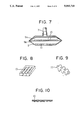
- FIGS. 8 though 10 are views of various types of magnets which can be employed in the embodiments of FIGS. 6 and 7.
- FIG. 11 is a schematic cross-sectional view of a fuel tank being cleaned in accordance with the method of the present invention.
- FIG. 12 is a schematic cross-sectional view of a fuel tank being cleaned in accordance with another form of the same method.
- a welded fuel tank 1 for an automobile comprises an upper fuel tank section 1a and a lower fuel tank section 1b which are joined together by seam welding along confronting flanges to form a welded joint 2.
- a fuel pump 12 is inserted into the fuel tank 1 through an installation hole 1c formed in the upper fuel tank section 1a.
- a permanent magnet 3 is secured to the outside of the bottom of the fuel tank 1 in the vicinity of the suction port of the fuel pump.
- the permanent magnet 3 constitutes magnet means for collecting magnetic particles (weld spatter) which remain within the fuel tank 1 after its manufacture.
- the permanent magnet 3 can be secured to the underside of the fuel tank 1 by any means which will enable it to withstand the vibrations and accelerations to which it is subjected during operation of the automobile in which the fuel tank 1 is installed. If the fuel tank 1 is made of a magnetic material, the magnet 3 can be attached to the fuel tank 1 by the magnetic attraction of the magnet 3 for the fuel tank 1. Alternatively, it can be bonded or clamped to the fuel tank 1. As is normal, the fuel pump 12 is placed within a well 14 to prevent the pump from running dry if the tank is tilted when only a small amount of fuel remains in it, and a fuel discharge pipe 16 extends from the pump to the exterior of the tank. The fuel pump has a suction port in its lower end, protected by a filter cap 18, for example as illustrated in EP-A-0191362. The magnet 3 is mounted directly below the pump, therefore close to the suction port of the pump.
- the illustrated fuel tank 1 is installed in an automobile and is filled with fuel. At this time, spatter which was produced at the time of welding still remains in small gaps within the welded joint 2. When the automobile moves, the fuel tank 1 is subjected to vibrations, shocks, and accelerations which dislodge some of the spatter within the gaps in the joint 2, and the dislodged spatter enters the fuel within the fuel tank 1. Because the spatter has a higher density than the fuel, the spatter sinks to the bottom of the fuel tank 1.
- the vibrations of the fuel tank 1 cause the spatter to move about the bottom of the fuel tank 1, and any of the spatter which comes in the vicinity of the magnet 3 will be attracted by the magnet 3, held firmly against the bottom surface of the fuel tank 1 by magnetic attraction, and prevented from further movement. Since the magnet 3 is disposed in the vicinity of the suction port of the fuel pump, spatter is trapped by the magent, mainly within the well 14, and thereby prevented from entering the fuel pump. Therefore, wear of the commutator and brushes of the fuel pump motor due to spatter entering therebetween can be eliminated, and the reliability and life span of the fuel pump can be greatly increased. Furthermore, the cost of installing a magnet 3 on the bottom of the fuel tank 1 is less than the cost of trying to completely remove the spatter from the fuel tank 1 during its manufacture by cleaning out the fuel tank 1.
- FIG. 2 illustrates a second embodiment of the present invention which differs from the first embodiment in that the magnet means is in the form of an electromagnet 4 comprising a coil of wire which is secured to the outside of a fuel tank 1 in the same position as the permanent magnet 3 of FIG. 1. So that the electromagnet 4 will be able to withstand vibrations and forces acting on it when the automobile is moving, it is secured to the bottom of the fuel tank by a mechanical fastener such as a strap which encircles the electromagnet 4, although other securing means can also be used.
- a mechanical fastener such as a strap which encircles the electromagnet 4, although other securing means can also be used.
- the operation and advantages of this embodiment are identical to those of the previous embodiment.
- FIG. 3 illustrates a third embodiment of the present invention in which the magnet means is in the form of a plurality of spherical magnets 5 which rest on the bottom surface of the inside of the fuel tank 1. Because the magnets 5 are round, they can roll about the inside of the fuel tank 1 when the fuel tank 1 is subjected to vibrations or accelerations or when it is tilted. As they roll about the fuel tank 1, the magnets 5 catch spatter and prevent the spatter from entering the fuel pump. The structure and operation of this embodiment is otherwise identical to that of the previous embodiment. The larger the surface area of the spherical magnets 5, the greater their ability to catch spatter and other magnetic particles. Therefore, the effectiveness of the spherical magnets 5 can be increased by forming surface irregularities therein.
- FIG. 4 is an enlarged view of one of the magnets 5 of FIG. 3 which has dimples 5a formed on its surface for the purpose of increasing the surface area.
- these spherical magnets are immersed in the contents of the tank, they must be made of a material resistant to the tank contents.
- Metal magnets in general cannot be used, first because of the risk of corrosion of the magnets, second because magnets made of metal will normally have a small number of distinct poles, consequently regions of high field and regions of low field which will not attract and trap spatter particles.
- Magnets to be placed inside the tank should therefore be made of resistant non-corrodible material such as ferrite or ceramic magnet materials, and furthermore should be such as to have an essentially uniform surface distribution of the magnetic field, so that they will be able to attract spatter substantially uniformly over their entire surface.
- Magnet materials comprising magnet particles dispersed in a matrix, for example of a suitable resistent plastics or rubber composition, can be used.
- the magnets In the case of loose spherical magnets such as shown in FIG. 3, the magnets must be discouraged from sticking to each other. Accordingly, they will in general have a relatively low but uniform surface field, sufficiently weak for attraction between the individual magnets to be broken by shaking or vibration of the fuel tank.
- the interior of the fuel tank will normally be cleaned, at least roughly, before the application of magnets to trap residual spatter.
- the amount of spatter which has to be trapped by the magnets is therefore relatively small, typically about one gram in a sixty liter tank, mostly trapped in the weld seam. This amount of spatter can be successfully trapped by magnets of relatively low surface field and area.
- Spherical magnets as shown in FIG. 3, or other forms of magnet placed inside the tank can be used to trap spatter before the tank is put into use, being removed with the spatter they have collected, or can be left in the tank during use, to immobilise spatter which may become dislodged during use.
- Movable magnets like the spherical magnets 5 have the advantage over stationary magnets in that by moving about the inside of the fuel tank 1 they are able to catch a greater amount of spatter than can stationary magnets.
- the magnet means can also be in the form of a stationary magnet inside the tank, and FIG. 5 illustrates a fourth embodiment of the present invention in which an electromagnet 6 comprising a coil of wire is secured to the bottom surface of the inside of the fuel tank 1 in the vicinity of the suction port of the fuel pump.
- This embodiment provides the same effects as the previous embodiments.
- an electromagnet 6 it is also possible to secure a permanent magnet to the bottom surface of the inside of the fuel tank 1.
- the magnet means is a magnet which is secured to the outside of the fuel tank 1, there is no restriction on the material constituting the magnet, but if the magnet means is a magnet which is disposed inside the fuel tank 1, as the magnet is immersed in fuel during use, it must be made of a material which is resistant to the fuel.
- One suitable type of permanent magnet is a plastic magnet formed by adding powder of a ferrite magnet powder or powder of a rare earth magnet to an acetal resin. A sintered body comprising these substances is also suitable.
- a plastic magnet has the advantage that it can be easily formed into a desired shape.
- a coil of magnet wire which has good resistance to fuels, is suitable.
- FIG. 6 illustrates a hollow fuel filter 8 of the fifth embodiment of the present invention.
- the fuel filter 8 is in the form of a bag which is installed on the suction port 7 of a fuel pump.
- the bag can be made of a material such as a synthetic woven fabric which has excellent resistance to fuels.
- a permanent magnet 10 is disposed inside the fuel filter 8.
- the permanent magnets 10 are made of a material having good resistance to fuels and can be made of the same material as the spherical magnets 5 shown in FIG. 3. The magnets 10 catch spatter as it passes through the filter 8 together with the fuel and prevents the spatter from entering the suction port 7.
- magnets 10 there is no restriction on the shape of the magnets 10 except that they should not adversely affect the head produced by the fuel pump. Magnets 10 in the form of simple shapes such as rectangles, circles, or ellipses of constant thickness all work effectively. A permanent magnet essentially in the shape of a plate is effective, the fuel flow being forced to go past the ends of the magnet. However, the magnets 10 may also have more complex shapes having increased surface areas, such as the shapes shown in FIGS. 8 through 10. FIG. 8 illustrates a magnet 10 having holes formed therein, FIG. 9 illustrates a magnet 10 with protrusions on its surface, and FIG. 10 illustrates a magnet in the form of a net or grid of rubber or plastics magnet rods, typically 6 or 7 cm long. Many other shapes are also possible. Because of their large surface areas, such magnets can more effectively catch spatter than can magnets which are simple solids.
- FIG. 7 illustrates a multi-layer fuel filter 9 in accordance with another embodiment of the present invention which has partitions 9a which surround the magnets 10 and prevent pieces of the magnets 10 from entering the suction port 7.
- the partitions can be made, for example, of ordinary filter material, of mesh 120 micrometers.
- the structure of the embodiment of FIGS. 6 and 7 is otherwise identical to that of the previous embodiments, and the same benefits are achieved.
- the magnets 10 inside the fuel filter 8 or 9 can be used by themselves without other magnets, or they can be used in conjunction with another magnet disposed on the bottom of the fuel tank 1 as in the previous embodiments.
- the present invention also provides a method for cleaning a welded fuel tank during its manufacture.
- This method will be explained while referring to FIG. 11.
- This figure shows a fuel tank 1 just after it has been welded together by seam welding.
- a plurality of magnets 5 are inserted into the fuel tank 1 through a convenient opening, such as the fuel pump installation hole 1c.
- the size of the magnets 5 should be such as to enable their easy insertion and removal, and they preferably have a shape which enables them to roll about the inside of the fuel tank 1. Therefore, spherical magnets 5 like those used in the embodiment of FIG. 3 are suitable.
- There is no restriction on the type of magnet, and ferrite magnet, rare earth magnets, Alnico (Trade Mark) magnets, and plastic magnets can all be employed.
- the fuel tank 1 is rotated or vibrated by the application of external force. This is for the purpose of moving the magnets 5 about the inside of the fuel tank 1 and also to dislodge spatter which is caught inside gaps in the welded joint 2. As the magnets 5 roll about the fuel tank 1, they catch and hold magnetic spatter which is present within the tank 1. Other magnetic particles present in the tank 1 such as those formed during machining operations are also caught. After sufficient movement of the magnets 5, they are removed from the fuel tank 1 together with the spatter and other particles which are attached to the magnets 5. In this way, spatter can be efficiently removed from the inside of the fuel tank 1. This cleaning method is less costly than conventional cleaning methods for removing spatter from the inside of a fuel tank.
- the tank may be cleaned by conventional means, at least roughly, before insertion of the magnets.
- the magnets may be used in conjunction with a cleaning fluid.
- the magnets 5 can be kept inside a flexible sack 11 having dimensions small enough to enable it to easily pass through the installation hole 1c of the fuel tank 1.
- Various materials can be used for the sack 11, including a synthetic fiber net, nonwoven fabric, natural fabric, and a metal net.
Abstract
A 3 fuel tank has a magnet 3 disposed on the inside or outside thereof in the vicinity of a fuel pump 12 which is housed inside the fuel tank. The magnet collects magnetic spatter which remains inside the fuel tank after welding and prevents the spatter from entering the fuel pump. The magnet may be a permanent magnet or an electromagnet, and it may be disposed outside the pump or in the fuel filter of the fuel pump. A cleaning method for a welded fuel tank comprises introducing a magnet into a fuel tank after welding, vibrating the fuel tank so that the magnet will move about the inside of the fuel tank and collect magnetic spatter, and then removing the magnet and spatter from the fuel tank.
Description
This application is a divisional of application Ser. No. 07/318,641, filed Mar. 3, 1989, now pending.
This invention relates to the manufacture of welded containers. It has particular reference to the manufacture of welded tanks to be used in conjunction with electric discharge pumps. More particularly but not exclusively, it relates to the manufacture of welded fuel tanks of the type having a fuel pump housed therein, suitable for use in automotive vehicles.
Commonly, the fuel tank of an automobile is a welded body comprising upper and lower sections made of steel and joined to one another by seam welding. In the process of seam welding, small particles of metal, referred to as spatter, are formed and remain within the fuel tank, either scattered as loose particles, or trapped in the welded joint.
In many automobiles, a fuel pump and an electric pump motor are housed inside the fuel tank. In other vehicles the fuel pump and motor are housed outside the tank, more or less close to it. In operation, any steel spatter which remains inside the fuel tank after manufacture, can easily be drawn into the fuel pump with the fuel. Some of this spatter will reach the commutator region of the pump motor, and enter between the commutator and the motor brushes (vehicle fuel pump motors are normally DC commutator motors). As a result, the spatter increases wear of the commutator and brushes and shortens the life span of the motor. It may also enter pump or motor bearings and damage these.
It is therefore customary to clean the inside of a fuel tank after welding, to remove as much of the spatter as possible, but because the spatter is extremely small, ranging from 1 to several hundred micrometers in diameter, it is impossible to remove all of the spatter by conventional cleaning methods. Furthermore, this conventional cleaning is unable to remove spatter lodged in minute gaps in the welded joint. When the fuel tank is mounted in a vehicle and filled with fuel, vibrations and shocks which are produced when the automobile moves dislodge some of the spatter from the welded joint, and this dislodged spatter is drawn into the fuel pump with the fuel.
Although fuel pumps commonly have filters at their suction ports, such filters are generally designed to pass particles having a diameter of one hundred micrometers or less. Much of the spatter has a particle diameter smaller than this, and therefore can pass through the filter and enter the fuel pump. To stop entry of the spatter by making the filter finer, would increase the load on the pump and alter the fuel flow characteristics, so there is a practical limit to the extent to which a filter can be used to trap the spatter. It is an object of the present invention to provide a means and method for removing or trapping spatter in a welded container, and in particular, for preventing spatter from entering a fuel pump or other pump.
Fuel tanks and other containers are commonly made of steel and consequently the spatter consists of small magnetic particles.
In accordance with the present invention we propose to trap the spatter magnetically, the trapped spatter being then removed from the container, or else magnetically fixed within the container so that it cannot enter a discharge pump disposed in or connected to the container.
In one aspect, the present invention resides in a container for a liquid incorporating at least one seam weld, and at least one magnet associated with the container for magnetically collecting magnetic particles remaining in the container after formation of the seam weld(s).
The said magnet or magnets can be permanent or electromagnets, and can be disposed either on the outside of or inside the container.
In the case of a container with an internal discharge pump, the magnet or magnets should be disposed in the vicinity of the suction port of the pump so as to trap spatter before it can enter the pump.
In one preferred arrangement, a magnet is disposed inside an inlet filter of the discharge pump.
If the magnet or magnets are disposed on the outside of the container, there is no restriction on the materials constituting the magnets. If a magnet is to be disposed inside the container, it must be made of a material resistant to the liquid for which the container is intended, that is to say, petrol or diesel oil in the case of a fuel tank.
The magnet or magnets can be of any shape. They can be stationary or movable, permanently in position or removable.
In one preferred arrangement, at least one magnet, shaped so that it can roll, is placed inside the container so that it can roll on the bottom surface of the interior of the container when the container is tilted or vibrated before or during use, therefore increasing the amount of spatter which the magnet can collect.
In the case of a magnet applied to the exterior of the container, it will normally be necessary to leave the magnet permanently in place and operational, so as to hold the spatter immobile on the internal surface of the container adjacent the external magnet.
In the case of a magnet placed inside the container, it may be left in the container during use, to collect and trap spatter particles during use as well as before use, or it may be used to collect spatter before the container is used, being removed from the container before the container is put into use.
In another aspect, the present invention resides in a method of making a container of magnetic material for a liquid, comprising seam welding portions of the container, and applying at least one magnet to the container thereby magnetically trapping magnetic particles remaining in the container after seam welding.
The present invention further resides in a method of cleaning a welded fuel tank having a plurality of fuel tank sections which are joined together by seam welding, comprising: introducing a magnet into the inside of said fuel tank after said welding has been performed; applying external force to said fuel tank so as to dislodge magnetic particles which were formed during said seam welding and which are trapped in the seam-welded portions of said fuel tank, and so as to make said magnet move around the inside of said fuel tank and contact said magnetic particles, whereby said magnet catches said magnetic particles; and removing said magnet from said fuel tank.
Preferably the magnet has a shape such that it can roll about the inside of the fuel tank. In a preferred embodiment, a plurality of such magnets are enclosed in a bag within the fuel tank, during the cleaning operation, the bag making it easier to introduce the magnets into the fuel tank and remove them from it after cleaning.
The present invention will be further described with reference to the accompanying drawings, in which:
FIG. 1 is a schematic cross-sectional view of a first embodiment of a fuel tank in accordance with the present invention.
FIG. 2 is a schematic cross-sectional view of a second embodiment of the present invention which employs an electromagnet.
FIG. 3 is a schematic cross-sectional view of a third embodiment of the present invention which employs spherical magnets.
FIG. 4 is an enlarged view of one of the spherical magnets of FIG. 3.
FIG. 5 is a schematic cross-sectional view of a fourth embodiment of the present invention which employs an electromagnet inside a fuel tank.
FIG. 6 is a schematic cross-sectional view of a fuel pump filter of a fifth embodiment of the present invention.
FIG. 7 is a schematic cross-sectional view of a fuel pump filter of a sixth embodiment of the present invention.
FIGS. 8 though 10 are views of various types of magnets which can be employed in the embodiments of FIGS. 6 and 7.
FIG. 11 is a schematic cross-sectional view of a fuel tank being cleaned in accordance with the method of the present invention.
FIG. 12 is a schematic cross-sectional view of a fuel tank being cleaned in accordance with another form of the same method.
In the drawings, the same reference numerals indicate the same or corresponding parts.
Hereinbelow, a number of preferred embodiments of a fuel tank in accordance with the present invention will be described while referring to the accompanying drawings. FIG. 1 of which illustrates a first embodiment. As shown in this Figure, a welded fuel tank 1 for an automobile comprises an upper fuel tank section 1a and a lower fuel tank section 1b which are joined together by seam welding along confronting flanges to form a welded joint 2. A fuel pump 12 is inserted into the fuel tank 1 through an installation hole 1c formed in the upper fuel tank section 1a. A permanent magnet 3 is secured to the outside of the bottom of the fuel tank 1 in the vicinity of the suction port of the fuel pump. The permanent magnet 3 constitutes magnet means for collecting magnetic particles (weld spatter) which remain within the fuel tank 1 after its manufacture.
The permanent magnet 3 can be secured to the underside of the fuel tank 1 by any means which will enable it to withstand the vibrations and accelerations to which it is subjected during operation of the automobile in which the fuel tank 1 is installed. If the fuel tank 1 is made of a magnetic material, the magnet 3 can be attached to the fuel tank 1 by the magnetic attraction of the magnet 3 for the fuel tank 1. Alternatively, it can be bonded or clamped to the fuel tank 1. As is normal, the fuel pump 12 is placed within a well 14 to prevent the pump from running dry if the tank is tilted when only a small amount of fuel remains in it, and a fuel discharge pipe 16 extends from the pump to the exterior of the tank. The fuel pump has a suction port in its lower end, protected by a filter cap 18, for example as illustrated in EP-A-0191362. The magnet 3 is mounted directly below the pump, therefore close to the suction port of the pump.
The illustrated fuel tank 1 is installed in an automobile and is filled with fuel. At this time, spatter which was produced at the time of welding still remains in small gaps within the welded joint 2. When the automobile moves, the fuel tank 1 is subjected to vibrations, shocks, and accelerations which dislodge some of the spatter within the gaps in the joint 2, and the dislodged spatter enters the fuel within the fuel tank 1. Because the spatter has a higher density than the fuel, the spatter sinks to the bottom of the fuel tank 1. The vibrations of the fuel tank 1 cause the spatter to move about the bottom of the fuel tank 1, and any of the spatter which comes in the vicinity of the magnet 3 will be attracted by the magnet 3, held firmly against the bottom surface of the fuel tank 1 by magnetic attraction, and prevented from further movement. Since the magnet 3 is disposed in the vicinity of the suction port of the fuel pump, spatter is trapped by the magent, mainly within the well 14, and thereby prevented from entering the fuel pump. Therefore, wear of the commutator and brushes of the fuel pump motor due to spatter entering therebetween can be eliminated, and the reliability and life span of the fuel pump can be greatly increased. Furthermore, the cost of installing a magnet 3 on the bottom of the fuel tank 1 is less than the cost of trying to completely remove the spatter from the fuel tank 1 during its manufacture by cleaning out the fuel tank 1.
FIG. 2 illustrates a second embodiment of the present invention which differs from the first embodiment in that the magnet means is in the form of an electromagnet 4 comprising a coil of wire which is secured to the outside of a fuel tank 1 in the same position as the permanent magnet 3 of FIG. 1. So that the electromagnet 4 will be able to withstand vibrations and forces acting on it when the automobile is moving, it is secured to the bottom of the fuel tank by a mechanical fastener such as a strap which encircles the electromagnet 4, although other securing means can also be used. The operation and advantages of this embodiment are identical to those of the previous embodiment.
When an electromagnet is used, it will become de-energized when the vehicle ignition is switched off and therefore will provide only intermittent immobilisation of the spatter. This does not impair its effectiveness in protecting the pump, because when the magnet is de-energized, the pump is naturally also inoperative.
FIG. 3 illustrates a third embodiment of the present invention in which the magnet means is in the form of a plurality of spherical magnets 5 which rest on the bottom surface of the inside of the fuel tank 1. Because the magnets 5 are round, they can roll about the inside of the fuel tank 1 when the fuel tank 1 is subjected to vibrations or accelerations or when it is tilted. As they roll about the fuel tank 1, the magnets 5 catch spatter and prevent the spatter from entering the fuel pump. The structure and operation of this embodiment is otherwise identical to that of the previous embodiment. The larger the surface area of the spherical magnets 5, the greater their ability to catch spatter and other magnetic particles. Therefore, the effectiveness of the spherical magnets 5 can be increased by forming surface irregularities therein. FIG. 4 is an enlarged view of one of the magnets 5 of FIG. 3 which has dimples 5a formed on its surface for the purpose of increasing the surface area.
Since these spherical magnets are immersed in the contents of the tank, they must be made of a material resistant to the tank contents. Metal magnets in general cannot be used, first because of the risk of corrosion of the magnets, second because magnets made of metal will normally have a small number of distinct poles, consequently regions of high field and regions of low field which will not attract and trap spatter particles.
Magnets to be placed inside the tank should therefore be made of resistant non-corrodible material such as ferrite or ceramic magnet materials, and furthermore should be such as to have an essentially uniform surface distribution of the magnetic field, so that they will be able to attract spatter substantially uniformly over their entire surface. Magnet materials comprising magnet particles dispersed in a matrix, for example of a suitable resistent plastics or rubber composition, can be used. In the case of loose spherical magnets such as shown in FIG. 3, the magnets must be discouraged from sticking to each other. Accordingly, they will in general have a relatively low but uniform surface field, sufficiently weak for attraction between the individual magnets to be broken by shaking or vibration of the fuel tank.
It is to be understood that the interior of the fuel tank will normally be cleaned, at least roughly, before the application of magnets to trap residual spatter. The amount of spatter which has to be trapped by the magnets is therefore relatively small, typically about one gram in a sixty liter tank, mostly trapped in the weld seam. This amount of spatter can be successfully trapped by magnets of relatively low surface field and area.
Spherical magnets as shown in FIG. 3, or other forms of magnet placed inside the tank, can be used to trap spatter before the tank is put into use, being removed with the spatter they have collected, or can be left in the tank during use, to immobilise spatter which may become dislodged during use.
Movable magnets like the spherical magnets 5 have the advantage over stationary magnets in that by moving about the inside of the fuel tank 1 they are able to catch a greater amount of spatter than can stationary magnets. However, the magnet means can also be in the form of a stationary magnet inside the tank, and FIG. 5 illustrates a fourth embodiment of the present invention in which an electromagnet 6 comprising a coil of wire is secured to the bottom surface of the inside of the fuel tank 1 in the vicinity of the suction port of the fuel pump. This embodiment provides the same effects as the previous embodiments. Instead of an electromagnet 6, it is also possible to secure a permanent magnet to the bottom surface of the inside of the fuel tank 1.
If the magnet means is a magnet which is secured to the outside of the fuel tank 1, there is no restriction on the material constituting the magnet, but if the magnet means is a magnet which is disposed inside the fuel tank 1, as the magnet is immersed in fuel during use, it must be made of a material which is resistant to the fuel. One suitable type of permanent magnet is a plastic magnet formed by adding powder of a ferrite magnet powder or powder of a rare earth magnet to an acetal resin. A sintered body comprising these substances is also suitable. In addition to having resistance to fuels, a plastic magnet has the advantage that it can be easily formed into a desired shape. As an electromagnet which is immersed in fuel inside the fuel tank 1, a coil of magnet wire, which has good resistance to fuels, is suitable.
In the previously described embodiments, the magnet means is disposed in the vicinity of the suction port of the fuel pump, but it is also possible to dispose the magnet means inside the fuel filter of the fuel pump itself. FIG. 6 illustrates a hollow fuel filter 8 of the fifth embodiment of the present invention. The fuel filter 8 is in the form of a bag which is installed on the suction port 7 of a fuel pump. The bag can be made of a material such as a synthetic woven fabric which has excellent resistance to fuels. A permanent magnet 10 is disposed inside the fuel filter 8. The permanent magnets 10 are made of a material having good resistance to fuels and can be made of the same material as the spherical magnets 5 shown in FIG. 3. The magnets 10 catch spatter as it passes through the filter 8 together with the fuel and prevents the spatter from entering the suction port 7.
There is no restriction on the shape of the magnets 10 except that they should not adversely affect the head produced by the fuel pump. Magnets 10 in the form of simple shapes such as rectangles, circles, or ellipses of constant thickness all work effectively. A permanent magnet essentially in the shape of a plate is effective, the fuel flow being forced to go past the ends of the magnet. However, the magnets 10 may also have more complex shapes having increased surface areas, such as the shapes shown in FIGS. 8 through 10. FIG. 8 illustrates a magnet 10 having holes formed therein, FIG. 9 illustrates a magnet 10 with protrusions on its surface, and FIG. 10 illustrates a magnet in the form of a net or grid of rubber or plastics magnet rods, typically 6 or 7 cm long. Many other shapes are also possible. Because of their large surface areas, such magnets can more effectively catch spatter than can magnets which are simple solids.
In order to prevent the magnets 10 or pieces thereof from being sucked into the suction port 7 in the event that the magnets 10 become damaged, there is preferably some member which separates the magnets 10 from the suction port 7. FIG. 7 illustrates a multi-layer fuel filter 9 in accordance with another embodiment of the present invention which has partitions 9a which surround the magnets 10 and prevent pieces of the magnets 10 from entering the suction port 7. The partitions can be made, for example, of ordinary filter material, of mesh 120 micrometers.
The structure of the embodiment of FIGS. 6 and 7 is otherwise identical to that of the previous embodiments, and the same benefits are achieved. The magnets 10 inside the fuel filter 8 or 9 can be used by themselves without other magnets, or they can be used in conjunction with another magnet disposed on the bottom of the fuel tank 1 as in the previous embodiments.
The present invention also provides a method for cleaning a welded fuel tank during its manufacture. This method will be explained while referring to FIG. 11. This figure shows a fuel tank 1 just after it has been welded together by seam welding. After the completion of welding, a plurality of magnets 5 are inserted into the fuel tank 1 through a convenient opening, such as the fuel pump installation hole 1c. The size of the magnets 5 should be such as to enable their easy insertion and removal, and they preferably have a shape which enables them to roll about the inside of the fuel tank 1. Therefore, spherical magnets 5 like those used in the embodiment of FIG. 3 are suitable. There is no restriction on the type of magnet, and ferrite magnet, rare earth magnets, Alnico (Trade Mark) magnets, and plastic magnets can all be employed.
Next, the fuel tank 1 is rotated or vibrated by the application of external force. This is for the purpose of moving the magnets 5 about the inside of the fuel tank 1 and also to dislodge spatter which is caught inside gaps in the welded joint 2. As the magnets 5 roll about the fuel tank 1, they catch and hold magnetic spatter which is present within the tank 1. Other magnetic particles present in the tank 1 such as those formed during machining operations are also caught. After sufficient movement of the magnets 5, they are removed from the fuel tank 1 together with the spatter and other particles which are attached to the magnets 5. In this way, spatter can be efficiently removed from the inside of the fuel tank 1. This cleaning method is less costly than conventional cleaning methods for removing spatter from the inside of a fuel tank. However, the tank may be cleaned by conventional means, at least roughly, before insertion of the magnets. The magnets may be used in conjunction with a cleaning fluid. In order to make it easier to insert and remove the magnets 5, as shown in FIG. 12, throughout the cleaning operation, the magnets 5 can be kept inside a flexible sack 11 having dimensions small enough to enable it to easily pass through the installation hole 1c of the fuel tank 1. Various materials can be used for the sack 11, including a synthetic fiber net, nonwoven fabric, natural fabric, and a metal net.
Claims (7)
1. A fuel filtration apparatus comprising:
a fuel tank having a seam weld;
a fuel pump having a suction port disposed inside the fuel tank;
a fuel filter element disposed in the fuel tank and having a chamber communicating with the suction port of the fuel pump; and
a magnet disposed inside the chamber of the fuel filter element for collecting magnetic particles.
2. An apparatus as claimed in claim 1 wherein the filter element is equipped with at least one partition which separates the magnet from the suction port.
3. An apparatus as claimed in claim 1 wherein:
the filter element comprises a bottom through which liquid can pass, a first partition through which liquid can pass separated from the bottom, and a second partition through which liquid can pass disposed between the first partition and the suction port; and
said magnet comprises at least one magnet disposed on the bottom of the filter element and at least one magnet is disposed on the first partition.
4. An apparatus as claimed in claim 1 wherein the magnet has perforations through which liquid can pass formed therein.
5. An apparatus as claimed in claim 1 wherein the magnet comprises a bar having projections formed thereon.
6. An apparatus as claimed in claim 1 wherein the magnet comprises a grid.
7. An apparatus as claimed in claim 1 wherein the magnet comprising a plurality of magnets disposed in the chamber of the filter element in a plurality of spaced apart layers.
Applications Claiming Priority (6)
| Application Number | Priority Date | Filing Date | Title |
|---|---|---|---|
| JP5683088A JPH01228585A (en) | 1988-03-09 | 1988-03-09 | Method for cleaning interior of fuel tank |
| JP5682888A JPH01240448A (en) | 1988-03-09 | 1988-03-09 | Fuel tank |
| JP63056829A JPH01232176A (en) | 1988-03-09 | 1988-03-09 | Fuel pump |
| JP63-56829 | 1988-09-03 | ||
| JP63-56828 | 1988-09-03 | ||
| JP63-56830 | 1988-09-03 |
Related Parent Applications (1)
| Application Number | Title | Priority Date | Filing Date |
|---|---|---|---|
| US07/318,641 Division US5273193A (en) | 1988-03-09 | 1989-03-03 | Welded fuel tank having a magnet for collecting weld spatter and method for collecting weld spatter |
Publications (1)
| Publication Number | Publication Date |
|---|---|
| US5085768A true US5085768A (en) | 1992-02-04 |
Family
ID=27296047
Family Applications (2)
| Application Number | Title | Priority Date | Filing Date |
|---|---|---|---|
| US07/318,641 Expired - Fee Related US5273193A (en) | 1988-03-09 | 1989-03-03 | Welded fuel tank having a magnet for collecting weld spatter and method for collecting weld spatter |
| US07/606,951 Expired - Fee Related US5085768A (en) | 1988-03-09 | 1990-10-31 | Welded fuel tank |
Family Applications Before (1)
| Application Number | Title | Priority Date | Filing Date |
|---|---|---|---|
| US07/318,641 Expired - Fee Related US5273193A (en) | 1988-03-09 | 1989-03-03 | Welded fuel tank having a magnet for collecting weld spatter and method for collecting weld spatter |
Country Status (3)
| Country | Link |
|---|---|
| US (2) | US5273193A (en) |
| DE (1) | DE3907317A1 (en) |
| GB (2) | GB8903411D0 (en) |
Cited By (18)
| Publication number | Priority date | Publication date | Assignee | Title |
|---|---|---|---|---|
| US5375629A (en) * | 1993-08-17 | 1994-12-27 | Synthetic Industries, Inc. | Acetal fuel filter fabric |
| WO1997009275A1 (en) * | 1995-09-08 | 1997-03-13 | Williamson Carlton R | Magnetic filter for use in a fluid lubrication system |
| US5894830A (en) * | 1997-12-15 | 1999-04-20 | Caterpillar Inc. | Engine having a high pressure hydraulic system and low pressure lubricating system |
| WO2000005499A1 (en) * | 1998-07-20 | 2000-02-03 | Victorio Girardi | Method and device for treating fluid |
| US6412517B1 (en) * | 1997-09-25 | 2002-07-02 | Marwal Systems | Pump device for a gas oil tank of a motor vehicle |
| US20050109685A1 (en) * | 2003-11-20 | 2005-05-26 | Yasushi Fujita | Fuel tank |
| US20090266830A1 (en) * | 2008-04-24 | 2009-10-29 | Benjey Robert P | Fluid container component assembly |
| US8372278B1 (en) * | 2012-03-21 | 2013-02-12 | GM Global Technology Operations LLC | Liquid fuel strainer assembly |
| US20130133620A1 (en) * | 2011-11-25 | 2013-05-30 | Andreas Stihl Ag & Co. Kg | Handheld work apparatus and suction head for connection to a fuel line in a handheld work apparatus |
| GB2502383A (en) * | 2012-05-21 | 2013-11-27 | Adey Holdings 2008 Ltd | Separator device |
| CN103899457A (en) * | 2012-12-25 | 2014-07-02 | 重庆长安汽车股份有限公司 | Fuel tank capable of removing black metal impurities or scrap iron |
| US20140284286A1 (en) * | 2013-03-22 | 2014-09-25 | Caterpillar Inc. | System and Method for Filtering Fuel Within Fuel Tank |
| CN104204494A (en) * | 2012-01-12 | 2014-12-10 | 捷豹路虎有限公司 | Magnet assembly |
| US9149740B2 (en) | 2010-12-01 | 2015-10-06 | Adey Holdings (2008) Limited | Water and dirt separator |
| US20160115919A1 (en) * | 2009-12-04 | 2016-04-28 | Aisan Kogyo Kabushiki Kaisha | Filtering device |
| US9463471B2 (en) | 2010-12-01 | 2016-10-11 | Adey Holdings (2008) Limited | Water and dirt separator |
| US20170284344A1 (en) * | 2014-09-02 | 2017-10-05 | Titano S.R.L. | Internal combustion engine with amplified magnetizing effect |
| SE2150915A1 (en) * | 2021-07-08 | 2023-01-09 | Husqvarna Ab | Improved fuel and oil combination storage container |
Families Citing this family (16)
| Publication number | Priority date | Publication date | Assignee | Title |
|---|---|---|---|---|
| FR2677971B1 (en) * | 1991-06-19 | 1993-10-22 | Sollac | DECANTATION DEVICE FOR FUEL TANK, PARTICULARLY GAS-OIL. |
| DE4209959A1 (en) * | 1992-03-27 | 1993-09-30 | Bayerische Motoren Werke Ag | Use of a gas and liquid-tight welding process |
| DE4438094C2 (en) * | 1994-10-25 | 2000-10-12 | Bayerische Motoren Werke Ag | Swirl pot for a fuel tank |
| US6337012B1 (en) * | 2000-02-28 | 2002-01-08 | Arthur J. Devine | Universal magnetic filter insert |
| US7445082B2 (en) * | 2005-04-21 | 2008-11-04 | Nifco Inc. | Noise suppressing device and installation structure of same |
| NO330972B1 (en) * | 2008-04-17 | 2011-08-29 | Innovar Engineering As | Device by the cleaning magnet |
| DE102008051856A1 (en) * | 2008-10-17 | 2010-04-22 | Ab Skf | contraption |
| DE102010011292A1 (en) | 2010-03-13 | 2011-09-15 | Dr. Ing. H.C. F. Porsche Aktiengesellschaft | High-pressure fuel pump |
| DE102010036806A1 (en) * | 2010-08-02 | 2012-02-02 | Sun Lung Gear Works Co., Ltd. | Apparatus for magnetic cleaning of contaminated oil in e.g. gearbox, has handle comprising end connected with flexible disk-shaped or rod-shaped magnetic unit, where supporting element is provided at outer side of magnetic unit |
| DE102011053358A1 (en) | 2011-09-07 | 2013-03-07 | Dr. Ing. H.C. F. Porsche Aktiengesellschaft | Fuel pump, particularly single piston high-pressure fuel pump for internal combustion engines of passenger cars, has housing, piston mounted in housing and arranged in oil space of housing and drive shaft mounted in housing |
| DE102011117163B4 (en) | 2011-10-28 | 2015-03-05 | Ibs Filtran Kunststoff-/ Metallerzeugnisse Gmbh | A filter assembly |
| DE102013204050A1 (en) * | 2013-03-08 | 2014-09-11 | Bosch Emission Systems Gmbh & Co. Kg | Tank system, in particular for a fuel supply system or an exhaust gas purification system of a motor vehicle |
| DE102017111402A1 (en) | 2017-05-24 | 2018-11-29 | Amazonen-Werke H. Dreyer Gmbh & Co. Kg | cleaning device |
| US10434992B2 (en) | 2017-10-23 | 2019-10-08 | Toyota Motor Engineering & Manufacturing North America, Inc. | Systems and methods for the removal of ferrous debris from degreaser baths |
| IT202100004940A1 (en) * | 2021-03-03 | 2022-09-03 | Chien Chian Yeu | FUEL TANK CLEANER BALL |
| CN113530733A (en) * | 2021-08-02 | 2021-10-22 | 中车大连机车车辆有限公司 | Cleaning system and method for inflatable pressure sensing closed circulation fuel tank |
Citations (10)
| Publication number | Priority date | Publication date | Assignee | Title |
|---|---|---|---|---|
| SU199683A1 (en) * | DEVICE FOR CLEANING FUEL INPUT TO THE AIRCRAFT TANK PUMP | |||
| US2937755A (en) * | 1954-09-13 | 1960-05-24 | Acf Ind Inc | Filter for electric fuel pump |
| US4357237A (en) * | 1979-11-28 | 1982-11-02 | Sanderson Charles H | Device for the magnetic treatment of water and liquid and gaseous fuels |
| US4414951A (en) * | 1981-02-02 | 1983-11-15 | Frank Saneto | Vehicle fuel conditioning apparatus |
| JPS59160876A (en) * | 1983-03-02 | 1984-09-11 | Mitsubishi Electric Corp | Memory device |
| JPS604756A (en) * | 1983-06-21 | 1985-01-11 | Matsushita Electric Ind Co Ltd | Space heater combined with hot water supplier |
| US4613435A (en) * | 1985-07-02 | 1986-09-23 | Shoemaker Fred N | Magnetic oil filter |
| US4716024A (en) * | 1986-06-25 | 1987-12-29 | Goliarda Mugnai Trust | Magnetizing hydrocarbon fuels and other fluids |
| US4784762A (en) * | 1986-06-26 | 1988-11-15 | Taliaferro Sam W | Magnetic trap |
| US4808306A (en) * | 1986-09-12 | 1989-02-28 | Mitchell John | Apparatus for magnetically treating fluids |
Family Cites Families (31)
| Publication number | Priority date | Publication date | Assignee | Title |
|---|---|---|---|---|
| CA601179A (en) * | 1960-07-05 | Indiana General Corporation | Magnetic filter | |
| US1103358A (en) * | 1911-05-01 | 1914-07-14 | Henry Hess | Method of and apparatus for tempering iron and steel articles. |
| US1673837A (en) * | 1927-02-17 | 1928-06-19 | Siemens Ag | Magnetic separator |
| DE548853C (en) * | 1930-11-05 | 1932-04-20 | Otto Buettner | Device for the finest grinding of cement or the like. |
| US2358612A (en) * | 1942-03-24 | 1944-09-19 | Cleveland Worm & Gear Company | Magnetic drain plug |
| US2352958A (en) * | 1942-06-22 | 1944-07-04 | Gen Motors Corp | Electric fuel pump |
| US2345029A (en) * | 1942-11-30 | 1944-03-28 | Lisle Corp | Magnetic plug |
| US2436740A (en) * | 1943-09-21 | 1948-02-24 | Lisle Corp | Filter magnet structure |
| US2690842A (en) * | 1952-09-13 | 1954-10-05 | Spluvak Kalman | Fuel line cleaner device |
| BE519820A (en) * | 1952-11-27 | |||
| US2704156A (en) * | 1953-03-03 | 1955-03-15 | Dietrich W Botstiber | Self-closing magnetic drain unit |
| US2755932A (en) * | 1954-04-13 | 1956-07-24 | Milton M Cohn | Magnetic plug |
| US2877899A (en) * | 1955-04-04 | 1959-03-17 | Ernest J Newhouse | Magnetic collector and neutralizing element for engines and the like |
| US2936890A (en) * | 1957-05-16 | 1960-05-17 | Dietrich W Botstiber | Magnetic chip detector |
| US2915185A (en) * | 1958-01-08 | 1959-12-01 | Airtex Products Inc | Air dome and magnetic filter to automotive fuel pump lines |
| US2964190A (en) * | 1958-03-10 | 1960-12-13 | George T Smith | Magnetic trap for engine cooling system |
| US3061104A (en) * | 1959-08-17 | 1962-10-30 | John F Schaffner | Fuel tank outlet shield |
| US3171806A (en) * | 1960-07-15 | 1965-03-02 | John F Schaffner | Fuel filter |
| US3139403A (en) * | 1960-09-29 | 1964-06-30 | Eriez Mfg Co | Magnetic separator for removing traces of magnetic contamination from fluids |
| US3170871A (en) * | 1960-11-22 | 1965-02-23 | Moriya Saburo Miyata | Magnetic filter |
| US3306454A (en) * | 1962-09-24 | 1967-02-28 | Edmond F Webb | Fluid container with contaminantcollecting means |
| US3240341A (en) * | 1963-01-14 | 1966-03-15 | Rosaen Filter Co | Magnetized gasket assembly |
| US3306405A (en) * | 1965-04-30 | 1967-02-28 | Rosenblum Robert | Travelling case |
| US3373352A (en) * | 1965-08-02 | 1968-03-12 | Lisle Corp | Magnetic chip gauge utilizing a coil whose turns are short circuited by chips |
| NL6614233A (en) * | 1965-10-13 | 1967-04-14 | ||
| US4053409A (en) * | 1975-03-26 | 1977-10-11 | Caterpillar Tractor Co. | Removable filter assembly with bypass valve |
| JPS6027443Y2 (en) * | 1980-03-15 | 1985-08-19 | 本田技研工業株式会社 | fuel strainer |
| SE430383B (en) * | 1982-03-12 | 1983-11-14 | David Bertil Olof Carlvret | DEVICE FOR CLEANING A PARTICULAR LIQUID FLUID |
| US4551602A (en) * | 1982-06-23 | 1985-11-05 | Inoue-Japax Research Incorporated | Electrical machining using an aqueous solution with a recycled surface active agent |
| JPS59162354A (en) * | 1983-03-08 | 1984-09-13 | Nissan Motor Co Ltd | Fuel filter |
| JPS61175262A (en) * | 1985-01-29 | 1986-08-06 | Mitsubishi Electric Corp | Fuel feeding pump |
-
1989
- 1989-02-15 GB GB898903411A patent/GB8903411D0/en active Pending
- 1989-02-23 GB GB8904118A patent/GB2216450B/en not_active Expired - Fee Related
- 1989-03-03 US US07/318,641 patent/US5273193A/en not_active Expired - Fee Related
- 1989-03-07 DE DE3907317A patent/DE3907317A1/en active Granted
-
1990
- 1990-10-31 US US07/606,951 patent/US5085768A/en not_active Expired - Fee Related
Patent Citations (10)
| Publication number | Priority date | Publication date | Assignee | Title |
|---|---|---|---|---|
| SU199683A1 (en) * | DEVICE FOR CLEANING FUEL INPUT TO THE AIRCRAFT TANK PUMP | |||
| US2937755A (en) * | 1954-09-13 | 1960-05-24 | Acf Ind Inc | Filter for electric fuel pump |
| US4357237A (en) * | 1979-11-28 | 1982-11-02 | Sanderson Charles H | Device for the magnetic treatment of water and liquid and gaseous fuels |
| US4414951A (en) * | 1981-02-02 | 1983-11-15 | Frank Saneto | Vehicle fuel conditioning apparatus |
| JPS59160876A (en) * | 1983-03-02 | 1984-09-11 | Mitsubishi Electric Corp | Memory device |
| JPS604756A (en) * | 1983-06-21 | 1985-01-11 | Matsushita Electric Ind Co Ltd | Space heater combined with hot water supplier |
| US4613435A (en) * | 1985-07-02 | 1986-09-23 | Shoemaker Fred N | Magnetic oil filter |
| US4716024A (en) * | 1986-06-25 | 1987-12-29 | Goliarda Mugnai Trust | Magnetizing hydrocarbon fuels and other fluids |
| US4784762A (en) * | 1986-06-26 | 1988-11-15 | Taliaferro Sam W | Magnetic trap |
| US4808306A (en) * | 1986-09-12 | 1989-02-28 | Mitchell John | Apparatus for magnetically treating fluids |
Cited By (28)
| Publication number | Priority date | Publication date | Assignee | Title |
|---|---|---|---|---|
| US5375629A (en) * | 1993-08-17 | 1994-12-27 | Synthetic Industries, Inc. | Acetal fuel filter fabric |
| WO1997009275A1 (en) * | 1995-09-08 | 1997-03-13 | Williamson Carlton R | Magnetic filter for use in a fluid lubrication system |
| US6412517B1 (en) * | 1997-09-25 | 2002-07-02 | Marwal Systems | Pump device for a gas oil tank of a motor vehicle |
| US5894830A (en) * | 1997-12-15 | 1999-04-20 | Caterpillar Inc. | Engine having a high pressure hydraulic system and low pressure lubricating system |
| WO2000005499A1 (en) * | 1998-07-20 | 2000-02-03 | Victorio Girardi | Method and device for treating fluid |
| US20050109685A1 (en) * | 2003-11-20 | 2005-05-26 | Yasushi Fujita | Fuel tank |
| US7429322B2 (en) * | 2003-11-20 | 2008-09-30 | Honda Motor Co., Ltd. | Fuel tank with filters |
| US20090266830A1 (en) * | 2008-04-24 | 2009-10-29 | Benjey Robert P | Fluid container component assembly |
| US9816470B2 (en) * | 2009-12-04 | 2017-11-14 | Aisan Kogyo Kabushiki Kaisha | Filtering device |
| US20160115919A1 (en) * | 2009-12-04 | 2016-04-28 | Aisan Kogyo Kabushiki Kaisha | Filtering device |
| US9463471B2 (en) | 2010-12-01 | 2016-10-11 | Adey Holdings (2008) Limited | Water and dirt separator |
| US9149740B2 (en) | 2010-12-01 | 2015-10-06 | Adey Holdings (2008) Limited | Water and dirt separator |
| CN103133203A (en) * | 2011-11-25 | 2013-06-05 | 安德烈亚斯.斯蒂尔两合公司 | Hand-operated implement and suction head for connecting with a fuel line in a hand-held work device |
| US9273658B2 (en) * | 2011-11-25 | 2016-03-01 | Andreas Stihl Ag & Co. Kg | Handheld work apparatus and suction head for connection to a fuel line in a handheld work apparatus |
| US20130133620A1 (en) * | 2011-11-25 | 2013-05-30 | Andreas Stihl Ag & Co. Kg | Handheld work apparatus and suction head for connection to a fuel line in a handheld work apparatus |
| CN103133203B (en) * | 2011-11-25 | 2017-11-17 | 安德烈亚斯.斯蒂尔两合公司 | Hand-held power tool and the dust collecter for being connected wherein with fuel conduit |
| CN104204494A (en) * | 2012-01-12 | 2014-12-10 | 捷豹路虎有限公司 | Magnet assembly |
| CN104204494B (en) * | 2012-01-12 | 2017-03-22 | 捷豹路虎有限公司 | Magnet assembly |
| US8372278B1 (en) * | 2012-03-21 | 2013-02-12 | GM Global Technology Operations LLC | Liquid fuel strainer assembly |
| GB2502383B (en) * | 2012-05-21 | 2017-02-01 | Adey Holdings 2008 Ltd | In-line fitment for connecting a filter to a pipe |
| GB2502383A (en) * | 2012-05-21 | 2013-11-27 | Adey Holdings 2008 Ltd | Separator device |
| CN103899457B (en) * | 2012-12-25 | 2015-12-02 | 重庆长安汽车股份有限公司 | A kind of can the fuel tank of black removal metal impurities or iron filings |
| CN103899457A (en) * | 2012-12-25 | 2014-07-02 | 重庆长安汽车股份有限公司 | Fuel tank capable of removing black metal impurities or scrap iron |
| US20140284286A1 (en) * | 2013-03-22 | 2014-09-25 | Caterpillar Inc. | System and Method for Filtering Fuel Within Fuel Tank |
| US9470193B2 (en) * | 2013-03-22 | 2016-10-18 | Caterpillar Inc. | System and method for filtering fuel within fuel tank |
| US20170284344A1 (en) * | 2014-09-02 | 2017-10-05 | Titano S.R.L. | Internal combustion engine with amplified magnetizing effect |
| US10273912B2 (en) * | 2014-09-02 | 2019-04-30 | Titano S.R.L. | Internal combustion engine with amplified magnetizing effect |
| SE2150915A1 (en) * | 2021-07-08 | 2023-01-09 | Husqvarna Ab | Improved fuel and oil combination storage container |
Also Published As
| Publication number | Publication date |
|---|---|
| GB2216450B (en) | 1991-09-11 |
| US5273193A (en) | 1993-12-28 |
| DE3907317A1 (en) | 1989-09-21 |
| GB8903411D0 (en) | 1989-04-05 |
| DE3907317C2 (en) | 1993-03-04 |
| GB2216450A (en) | 1989-10-11 |
Similar Documents
| Publication | Publication Date | Title |
|---|---|---|
| US5085768A (en) | Welded fuel tank | |
| US4495074A (en) | Method and apparatus for filtration using ferromagnetic metal fibers | |
| US7655166B2 (en) | Evaporative emissions filter | |
| US20060231482A1 (en) | Integrated waffle fluid filter apparatus and method | |
| US4446019A (en) | Magnetic filtration in a spin-on fluid filter | |
| EP0956135A1 (en) | Filter having magnetic components and method of manufacturing same | |
| WO1997022395A9 (en) | Filter having magnetic components and method of manufacturing same | |
| WO2001028653A1 (en) | Filter and method for purifying liquids containing magnetic particles | |
| US5638786A (en) | Self-cleaning air filter for a fuel vapor recovery system | |
| EP0395738A4 (en) | Filter body with tapered tortuous passageways | |
| US7014772B2 (en) | Fibrous filter assembly and method | |
| US3463729A (en) | Magnetic filtration of transmission fluid | |
| CN2198021Y (en) | Improved struction of machine oil filter | |
| US6139737A (en) | Transmission fluid filter having a ferrite-filled nylon magnetic body | |
| CN104204494B (en) | Magnet assembly | |
| DE3731233C1 (en) | Soot accumulator for an exhaust gas cleaning system of an internal combustion engine | |
| JPS5952509A (en) | Magnetic separation apparatus | |
| US5505861A (en) | System for gravity settling of fine particles from a liquid | |
| JPH01228585A (en) | Method for cleaning interior of fuel tank | |
| JPH05309292A (en) | Strainer | |
| JPH01232176A (en) | Fuel pump | |
| JPH0344249Y2 (en) | ||
| KR19990026168U (en) | Float debris removal device using magnetic material | |
| JP2545859Y2 (en) | Solution foreign matter removal device in absorption chiller / heater | |
| US3426905A (en) | Replaceable filter unit for coolant systems of internal combustion engines |
Legal Events
| Date | Code | Title | Description |
|---|---|---|---|
| FEPP | Fee payment procedure |
Free format text: PAYOR NUMBER ASSIGNED (ORIGINAL EVENT CODE: ASPN); ENTITY STATUS OF PATENT OWNER: LARGE ENTITY |
|
| FPAY | Fee payment |
Year of fee payment: 4 |
|
| REMI | Maintenance fee reminder mailed | ||
| LAPS | Lapse for failure to pay maintenance fees | ||
| FP | Lapsed due to failure to pay maintenance fee |
Effective date: 20000204 |
|
| STCH | Information on status: patent discontinuation |
Free format text: PATENT EXPIRED DUE TO NONPAYMENT OF MAINTENANCE FEES UNDER 37 CFR 1.362 |