US5090199A - Apparatus for controlling air-fuel ratio for engine - Google Patents

Apparatus for controlling air-fuel ratio for engine Download PDF

Info

Publication number
US5090199A
US5090199A US07/626,829 US62682990A US5090199A US 5090199 A US5090199 A US 5090199A US 62682990 A US62682990 A US 62682990A US 5090199 A US5090199 A US 5090199A
Authority
US
United States
Prior art keywords
fuel ratio
air
target air
detection signal
engine
Prior art date
Legal status (The legal status is an assumption and is not a legal conclusion. Google has not performed a legal analysis and makes no representation as to the accuracy of the status listed.)
Expired - Lifetime
Application number
US07/626,829
Inventor
Kenji Ikuta
Toshio Kondo
Hiroshi Haraguchi
Current Assignee (The listed assignees may be inaccurate. Google has not performed a legal analysis and makes no representation or warranty as to the accuracy of the list.)
Denso Corp
Original Assignee
NipponDenso Co Ltd
Priority date (The priority date is an assumption and is not a legal conclusion. Google has not performed a legal analysis and makes no representation as to the accuracy of the date listed.)
Filing date
Publication date
Application filed by NipponDenso Co Ltd filed Critical NipponDenso Co Ltd
Assigned to NIPPONDENSO CO., LTD., A CORP. OF JAPAN reassignment NIPPONDENSO CO., LTD., A CORP. OF JAPAN ASSIGNMENT OF ASSIGNORS INTEREST. Assignors: HARAGUCHI, HIROSHI, IKUTA, KENJI, KONDO, TOSHIO
Application granted granted Critical
Publication of US5090199A publication Critical patent/US5090199A/en
Anticipated expiration legal-status Critical
Expired - Lifetime legal-status Critical Current

Links

Images

Classifications

    • FMECHANICAL ENGINEERING; LIGHTING; HEATING; WEAPONS; BLASTING
    • F02COMBUSTION ENGINES; HOT-GAS OR COMBUSTION-PRODUCT ENGINE PLANTS
    • F02DCONTROLLING COMBUSTION ENGINES
    • F02D41/00Electrical control of supply of combustible mixture or its constituents
    • F02D41/02Circuit arrangements for generating control signals
    • F02D41/04Introducing corrections for particular operating conditions
    • FMECHANICAL ENGINEERING; LIGHTING; HEATING; WEAPONS; BLASTING
    • F02COMBUSTION ENGINES; HOT-GAS OR COMBUSTION-PRODUCT ENGINE PLANTS
    • F02DCONTROLLING COMBUSTION ENGINES
    • F02D41/00Electrical control of supply of combustible mixture or its constituents
    • F02D41/02Circuit arrangements for generating control signals
    • F02D41/14Introducing closed-loop corrections
    • F02D41/1401Introducing closed-loop corrections characterised by the control or regulation method
    • FMECHANICAL ENGINEERING; LIGHTING; HEATING; WEAPONS; BLASTING
    • F02COMBUSTION ENGINES; HOT-GAS OR COMBUSTION-PRODUCT ENGINE PLANTS
    • F02DCONTROLLING COMBUSTION ENGINES
    • F02D41/00Electrical control of supply of combustible mixture or its constituents
    • F02D41/02Circuit arrangements for generating control signals
    • F02D41/14Introducing closed-loop corrections
    • F02D41/1438Introducing closed-loop corrections using means for determining characteristics of the combustion gases; Sensors therefor
    • F02D41/1439Introducing closed-loop corrections using means for determining characteristics of the combustion gases; Sensors therefor characterised by the position of the sensor
    • F02D41/1441Plural sensors
    • FMECHANICAL ENGINEERING; LIGHTING; HEATING; WEAPONS; BLASTING
    • F02COMBUSTION ENGINES; HOT-GAS OR COMBUSTION-PRODUCT ENGINE PLANTS
    • F02DCONTROLLING COMBUSTION ENGINES
    • F02D41/00Electrical control of supply of combustible mixture or its constituents
    • F02D41/02Circuit arrangements for generating control signals
    • F02D41/14Introducing closed-loop corrections
    • F02D41/1438Introducing closed-loop corrections using means for determining characteristics of the combustion gases; Sensors therefor
    • F02D41/1477Introducing closed-loop corrections using means for determining characteristics of the combustion gases; Sensors therefor characterised by the regulation circuit or part of it,(e.g. comparator, PI regulator, output)
    • F02D41/1479Using a comparator with variable reference
    • FMECHANICAL ENGINEERING; LIGHTING; HEATING; WEAPONS; BLASTING
    • F02COMBUSTION ENGINES; HOT-GAS OR COMBUSTION-PRODUCT ENGINE PLANTS
    • F02DCONTROLLING COMBUSTION ENGINES
    • F02D41/00Electrical control of supply of combustible mixture or its constituents
    • F02D41/02Circuit arrangements for generating control signals
    • F02D41/14Introducing closed-loop corrections
    • F02D41/1401Introducing closed-loop corrections characterised by the control or regulation method
    • F02D2041/1409Introducing closed-loop corrections characterised by the control or regulation method using at least a proportional, integral or derivative controller
    • FMECHANICAL ENGINEERING; LIGHTING; HEATING; WEAPONS; BLASTING
    • F02COMBUSTION ENGINES; HOT-GAS OR COMBUSTION-PRODUCT ENGINE PLANTS
    • F02DCONTROLLING COMBUSTION ENGINES
    • F02D41/00Electrical control of supply of combustible mixture or its constituents
    • F02D41/02Circuit arrangements for generating control signals
    • F02D41/14Introducing closed-loop corrections
    • F02D41/1401Introducing closed-loop corrections characterised by the control or regulation method
    • F02D2041/1413Controller structures or design
    • F02D2041/1415Controller structures or design using a state feedback or a state space representation
    • FMECHANICAL ENGINEERING; LIGHTING; HEATING; WEAPONS; BLASTING
    • F02COMBUSTION ENGINES; HOT-GAS OR COMBUSTION-PRODUCT ENGINE PLANTS
    • F02DCONTROLLING COMBUSTION ENGINES
    • F02D41/00Electrical control of supply of combustible mixture or its constituents
    • F02D41/02Circuit arrangements for generating control signals
    • F02D41/14Introducing closed-loop corrections
    • F02D41/1401Introducing closed-loop corrections characterised by the control or regulation method
    • F02D2041/1413Controller structures or design
    • F02D2041/1418Several control loops, either as alternatives or simultaneous
    • FMECHANICAL ENGINEERING; LIGHTING; HEATING; WEAPONS; BLASTING
    • F02COMBUSTION ENGINES; HOT-GAS OR COMBUSTION-PRODUCT ENGINE PLANTS
    • F02DCONTROLLING COMBUSTION ENGINES
    • F02D41/00Electrical control of supply of combustible mixture or its constituents
    • F02D41/02Circuit arrangements for generating control signals
    • F02D41/14Introducing closed-loop corrections
    • F02D41/1401Introducing closed-loop corrections characterised by the control or regulation method
    • F02D2041/1433Introducing closed-loop corrections characterised by the control or regulation method using a model or simulation of the system
    • FMECHANICAL ENGINEERING; LIGHTING; HEATING; WEAPONS; BLASTING
    • F02COMBUSTION ENGINES; HOT-GAS OR COMBUSTION-PRODUCT ENGINE PLANTS
    • F02DCONTROLLING COMBUSTION ENGINES
    • F02D41/00Electrical control of supply of combustible mixture or its constituents
    • F02D41/02Circuit arrangements for generating control signals
    • F02D41/14Introducing closed-loop corrections
    • F02D41/1438Introducing closed-loop corrections using means for determining characteristics of the combustion gases; Sensors therefor
    • F02D41/1444Introducing closed-loop corrections using means for determining characteristics of the combustion gases; Sensors therefor characterised by the characteristics of the combustion gases
    • F02D41/1454Introducing closed-loop corrections using means for determining characteristics of the combustion gases; Sensors therefor characterised by the characteristics of the combustion gases the characteristics being an oxygen content or concentration or the air-fuel ratio
    • F02D41/1456Introducing closed-loop corrections using means for determining characteristics of the combustion gases; Sensors therefor characterised by the characteristics of the combustion gases the characteristics being an oxygen content or concentration or the air-fuel ratio with sensor output signal being linear or quasi-linear with the concentration of oxygen

Definitions

  • the present invention relates to an air-fuel ratio control apparatus for an engine for controlling a fuel injection amount so that an air-fuel ratio of a mixture gas which is supplied to the engine is set to a stoichiometric air-fuel ratio.
  • an air-fuel ratio control apparatus for an engine in which a first oxygen concentration sensor (hereinafter referred to an air-fuel ratio sensor) which can obtain a detection signal which is linear to an air-fuel ratio of a mixture gas which is supplied to the engine is provided on the upstream side of a 3-component catalytic converter arranged in an exhaust pipe and a fuel injection amount is controlled so that an air-fuel ratio is set to a stoichiometric air-fuel ratio in accordance with the detection signal from the air-fuel ratio sensor, wherein a second oxygen concentration sensor (referred to an O 2 sensor) which can obtain a rich/lean detection signal for the air-fuel ratio of the mixture gas which is supplied to the engine is provided side by side with the air-fuel ratio sensor on the upstream side of the 3-component catalytic converter, and a deviation between an actual air-fuel ratio and the detection signal of the air-fuel ratio sensor is corrected on the basis of the detection signal from the O 2 sensor (for instance, refer to JP-A-56-
  • the air-fuel ratio is controlled in a manner such that the rich and lean air-fuel ratios are repeated at a short period with respect to the stoichiometric air-fuel ratio as a center value.
  • the detection signal of the O 2 sensor changes so that the rich (R) and lean (L) values are repeated at a short period as shown in (a) in FIG. 3. Therefore, if the air-fuel ratio is corrected on the basis of the detection signal of such a short period, since the air-fuel ratio is influenced by a fluctuation of the detection signal, the air-fuel ratio cannot be stably controlled.
  • the detection signal of the O 2 sensor is easily influenced by a certain special cylinder in dependence on the attaching position or the like.
  • a temperature is high in the upstream of the 3-component catalytic converter.
  • a copper component is included in the exhaust gas. Therefore, the O 2 sensor itself for correction remarkably deteriorates.
  • the present invention is made to solve the foregoing problems and it is an object of the invention to provide an air-fuel ratio control apparatus for an engine which properly corrects a deviation between an actual air-fuel ratio and a detection signal of an air-fuel ratio sensor and accurately controls the air-fuel ratio to a stoichiometric air-fuel ratio.
  • a first oxygen concentration sensor (36), arranged on the upstream side of the catalyst, for outputting a first detection signal which is linear to an air-fuel ratio of a mixture gas which is supplied to the engine;
  • target air-fuel ratio setting means (40) for setting a target air-fuel ratio in accordance with the second detection signal
  • fuel injection amount setting means (45) for setting a fuel injection amount which is supplied to the engine in accordance with the first detection signal and the target air-fuel ratio.
  • the target air-fuel ratio setting means has first target air-fuel ratio setting means for setting the target air-fuel ratio to a value on the lean side so as to be gradually reduced by every predetermined value per unit time in the case where the second detection signal indicates a rich state and for setting the target air-fuel ratio to a value on the rich side so as to be gradually increased by every predetermined value per unit time in the case where the second detection signal indicates a lean state.
  • the target air-fuel ratio setting means can also have:
  • first time detecting means for detecting a total time of times corresponding to the rich state in a predetermined period of time of the second detection signal
  • second time detecting means for detecting a total time of times corresponding to the lean state in the predetermined period of time of the second detection signal
  • second target air-fuel ratio setting means for setting the target air-fuel ratio to a value on the lean side so as to be gradually reduced by a predetermined value at a time in the case where the total time of the times of the rich state is longer than the total time of the times of the lean state and for setting the target air-fuel ratio to a value on the rich side so as to be gradually increased by a predetermined value at a time in the case where the total time of the times of the lean state is longer than the total time of the times of the rich state.
  • the fuel injection amount setting means periodically changes the target air-fuel ratio at a predetermined amplitude for a target air-fuel ratio which is set by the target air-fuel ratio setting means.
  • the target air-fuel ratio is set by the target air-fuel ratio setting means in accordance with the second detection signal which is output from the second oxygen concentration sensor. Then, the fuel injection amount is set by the fuel injection amount setting means in accordance with the first detection signal which is output from the first oxygen concentration sensor and the target air-fuel ratio.
  • FIG. 1 is a diagram corresponding to Claims of the present invention
  • FIG. 2 is a constructional diagram of an embodiment of the invention
  • FIG. 3 is a characteristic diagram of a detection signal of an O 2 sensor
  • FIG. 4 is a block diagram for explaining the operation of an air-fuel control in the embodiment
  • FIGS. 5 and 7 are block diagrams for explaining the operation of the embodiment
  • FIG. 6 is a characteristic diagram of a purification factor of a 3-component catalytic converter
  • FIGS. 8 and 9 are timing charts of the embodiment
  • FIG. 10 is a timing chart of another embodiment.
  • FIG. 11 is a flowchart for explaining the operation of another embodiment.
  • FIG. 2 is a schematic constructional diagram showing an engine 10 whose air-fuel ratio is controlled and its peripheral apparatuses. As shown in the diagram, in the embodiment, an ignition timing I g of an engine 10 and a fuel injection amount TAU are controlled by an electronic control unit (ECU) 20.
  • ECU electronice control unit
  • the engine 10 is of a spark ignition type of four cylinders and four cycles.
  • An intake air is sucked into each cylinder from the upstream through an air cleaner 11, an intake pipe 12, a throttle valve 13, a surge tank 14, and an intake branch pipe 15.
  • a fuel is fed with a pressure from a fuel tank (not shown) and is injected and supplied from fuel injection valves 16a, 16b, 16c, and 16d provided for the intake branch pipe 15.
  • the engine 10 has: a distributor 19 for distributing an electric signal of a high voltage which is supplied from an ignition circuit 17 to spark plugs 18a, 18b, 18c, and 18d of the cylinders; a rotational speed sensor 30, provided in the distributor 19, for detecting a rotational speed N e of the engine 10; a throttle sensor 31 for detecting an opening degree TH of the throttle valve 13; an intake pressure sensor 32 for detecting an intake pressure PM on the downstream side of the throttle valve 13; a warming-up sensor 33 for detecting a temperature T hw of cooling water of the engine 10; and an intake temperature sensor 34 for detecting a temperature T am of intake air.
  • the rotational speed sensor 30 is provided so as to face a ring gear which rotates synchronously with a crank shaft of the engine 10.
  • the sensor 30 outputs 24 pulse signals per rotation, that is, 720° CA of the engine 10 in proportion to the rotational speed N e .
  • the throttle sensor 31 outputs not only an analog signal corresponding to the throttle opening degree TH but also an on/off signal from an idle switch to detect that the throttle valve 13 is almost fully closed.
  • an exhaust pipe 35 of the engine 10 has therein a 3-component catalytic converter 38 to reduce harmful components (CO, HC, NOx, and the like) contained in the exhaust gas which is exhausted from the engine 10.
  • an air-fuel ratio sensor 36 as a first oxygen concentration sensor for outputting a linear detection signal according to an air-fuel ratio ⁇ of the mixture gas supplied to the engine 10 is provided on the upstream side of the 3-component catalytic converter 38.
  • An O 2 sensor 37 as a second oxygen concentration sensor for outputting a detection signal indicating whether the air-fuel ratio ⁇ of the mixture gas supplied to the engine 10 is rich or lean as compared with a stoichiometric air-fuel ratio ⁇ 0 is provided on the downstream side of the 3-component catalytic converter 38.
  • the ECU 20 is constructed as an arithmetic logic operation circuit mainly comprising well-know components such as CPU 21, ROM 22, RAM 23, backup RAM 24, and the like.
  • the ECU 20 is mutually connected through a bus 27 to an input port 25 for inputting detection signals from the sensors, an output port 26 to output control signals to actuators, and the like.
  • the ECU 20 receives through the input port 25 the signals indicative of the intake pressure PM, intake temperature T am , throttle opening degree TH, cooling water temperature T hw , air-fuel ratio ⁇ , rotational speed N e , and the like.
  • the ECU 20 calculates the fuel injection amount TAU and the ignition timing I g on the basis of those information and outputs control signals to the fuel injection valves 16a to 16d and the ignition circuit 17 through the output port 26.
  • the air-fuel ratio control will now be described hereinbelow.
  • the ECU 20 has previously been designed by the following method in order to execute the air-fuel ratio control.
  • the designing method which will be explained hereinbelow, is disclosed in JP-A-64-110853.
  • the model of the system for controlling the air-fuel ratio ⁇ using the autoregressive moving average model can be approximated by
  • a regulator is designed with respect to the above equations (5) and (6).
  • an integration term Z I (k) to absorb errors is added. ##EQU5## Due to this, the air-fuel ratio ⁇ and the correction coefficient FAF can be obtained.
  • the integration term Z I (k) is a value which is determined by a deviation between a target air-fuel ratio ⁇ TG and an actual air-fuel ratio ⁇ (k) and by an integration constant K a and is obtained by the following equation (7).
  • FIG. 4 is a block diagram of a system to control the air-fuel ratio ⁇ by which the model was designed as mentioned above.
  • the Z -1 transformation has been used to derive the air-fuel ratio correction coefficient FAF(k) from FAF(k-1) and the FAF(k) has been displayed.
  • the past air-fuel ratio correction coefficient FAF(k-1) is stored into the RAM 23 and is read out at the next control timing and is used.
  • a block P 1 surrounded by an alternate long and short dash line in FIG. 4 corresponds to a portion to decide the state variable amount X(k) in a state in which the air-fuel ratio ⁇ (k) is feedback controlled to the target air-fuel ratio ⁇ TG .
  • a block P 2 corresponds to a portion (accumulating portion) to obtain the integration term Z I (k).
  • a block P 3 corresponds to a portion to calculate the present air-fuel ratio correction coefficient FAF(k) from the state variable amount X(k) which was determined in the block P 1 and the integration term Z I (k) which was obtained in the block P 2 .
  • the optimum feedback gain K and the integration constant K a can be set by minimizing an evaluation function J which is shown by the following equation. ##EQU6##
  • the evaluation function J intends to minimize the deviation between the actual air-fuel ratio ⁇ (k) and the target air-fuel ratio ⁇ TG while restricting the motion of the air-fuel ratio correction coefficient FAF(k).
  • a weighting of the restriction to the air-fuel ratio correction coefficient FAF(k) can be changed by the values of weight parameters Q and R. Therefore, it is sufficient to determine the optimum feedback gain K and the integration constant K a by repeating simulations until the optimum control characteristics are obtained by variably changing the values of the weight parameters Q and R.
  • the optimum feedback gain K and the integration constant K a depend on the model constants a and b. Therefore, to assure the stability (robust performance) of the system for a fluctuation (parameter fluctuation) of the system to control the actual air-fuel ratio ⁇ it is necessary to design the optimum feedback gain K and the integration constant K a in consideration of fluctuation amounts of the model constants a and b. Accordingly, the simulations are executed in consideration of the fluctuations of the model constants a and b which can be actually caused, thereby deciding the optimum feedback gain K and the integration constant K a which satisfy the stability.
  • FIG. 5 shows a process to set the fuel injection amount TAU which is executed synchronously with the rotation (every 360° CA).
  • a fundamental fuel injection amount T p is calculated on the basis of the intake pressure PM, rotational speed N e , and the like.
  • step 102 a check is made to see if the feedback conditions of the air-fuel ratio ⁇ are satisfied or not.
  • the feedback conditions are such that the cooling water temperature T hw is equal to or higher than a predetermined value and a load and a rotational speed are not high as is well known. If the feedback conditions of the air-fuel ratio ⁇ are not satisfied in step 102, the air-fuel ratio correction coefficient FAF is set to 1 in step 103. Then, step 106 follows.
  • step 104 the target air-fuel ratio ⁇ TG is set in step 104 (which will be explained in detail hereinlater).
  • step 105 the air-fuel ratio correction coefficient FAF is set so that the air-fuel ratio ⁇ is equal to the target air-fuel ratio ⁇ TG .
  • the air-fuel ratio correction coefficient FAF is calculated by the equations (6) and (7) in accordance with the target air-fuel ratio ⁇ TG and the air-fuel ratio ⁇ (k) which is detected by the air-fuel ratio sensor 36.
  • step 106 a fuel injection amount is corrected for the fundamental fuel injection amount T p by the following equation in accordance with the air-fuel ratio correction coefficient FAF and another correction coefficient FALL, so that the fuel injection amount TAU is set.
  • An operation signal according to the fuel injection amount TAU which was set as mentioned above is output to the fuel injection valves 16a to 16d.
  • a center value ⁇ TGC of the target air-fuel ratio is set on the basis of the detection signal of the O 2 sensor 37 so as to correct a deviation between the actual air-fuel ratio and the detection signal of the air-fuel ratio sensor 36.
  • the center value ⁇ TGC is set to a value on the lean side by only a predetermined value ⁇ M .
  • the center value ⁇ TGC is set to a value on the rich side by only the predetermined value ⁇ M .
  • FIG. 6 shows characteristics of a purification factor ⁇ of the 3-component catalytic converter 38 to the air-fuel ratio ⁇ .
  • the air-fuel ratio is controlled within a range of a catalyst window W (hatched portion in the diagram) shown in FIG. 6. Since the catalyst window W is about 0.1%, the above predetermined value ⁇ M is set to be smaller than the value of W.
  • the deviation between the actual air-fuel ratio and the detection signal of the air-fuel ratio sensor also differs depending on the rotational speed N e and the intake pressure PM. That is, the air-fuel ratio at which the maximum purification factor ⁇ is obtained differs depending on the rotational speed N e and the intake pressure PM. Therefore, an air-fuel ratio at which the maximum purification factor ⁇ is obtained is previously derived as an initial value of the center value ⁇ TGC by the rotational speed N e and the intake pressure PM and is stored into the ROM 22. It is sufficient to read out such an air-fuel ratio from the ROM 22 at the start of the feedback control.
  • the initial value of the center value ⁇ TGC has characteristics such that it is set to a value on the rich side as the rotational speed N e and the intake pressure PM increase.
  • the target air-fuel ratio ⁇ TG is changed (dither control) periodically (dither period of T DZA ) at a predetermined amplitude (dither amplitude) ⁇ DZA within a range of the catalyst window W.
  • the optimum value at which the maximum purification factor ⁇ is obtained differs depending on the rotational speed N e and the intake pressure PM. Therefore, the optimum values of the dither amplitude ⁇ DZA and the dither period T DZA are previously obtained on the basis of the rotational speed N e and the intake pressure PM and stored into the ROM 22. It is sufficient to sequentially read out those optimum values from the ROM 22.
  • the center value ⁇ TGC of the target air-fuel ratio mentioned above is set.
  • step 201 a check is made to see if the detection signal from the O 2 sensor 37 indicates the rich state or the lean state. If the detection signal from the O 2 sensor 37 indicates the rich state, the center value ⁇ TGC is increased by only the predetermined value ⁇ M in step 202, that is, it is set to a value on the lean side ( ⁇ TGC ⁇ TGC + ⁇ M ).
  • step 201 if the detection signal from the O 2 sensor 37 indicates the lean state, the center value ⁇ TGC is decreased by only the predetermined value ⁇ M in step 203, that is, it is set to a value on the lean side ( ⁇ TGC ⁇ TGC - ⁇ M ).
  • steps 204 to 213 relate to the foregoing dither control.
  • step 204 a check is made to see if a count value of a counter CDZA is equal to or larger than the dither period T DZA or not.
  • the counter CDZA counts the dither period T DZA . If the count value of the counter CDZA is less than the dither period T DZA , the counter CDZA is counted up (CDZA ⁇ CDZA+1) in step 205. Then, step 213 follows.
  • the dither amplitude ⁇ DZA is set in step 207.
  • a dither amplitude ⁇ DZA the optimum value corresponding to the rotational speed N e and the intake pressure PM is previously obtained and stored into the ROM 22 as a two-dimensional map of the rotational speed N e and the intake pressure PM.
  • the dither amplitude ⁇ DZA is sequentially read out from the ROM 22.
  • the dither period T DZA is set. With respect to the dither period T DZA as well, in a manner similar to the dither amplitude ⁇ DZA , the optimum value is stored into the ROM 22 as a two-dimensional map of the rotational speed N e and the intake pressure PM. The dither period T DZA is sequentially read out from the ROM 22.
  • step 213 the target air-fuel ratio ⁇ TG is set by the following equation.
  • the target air-fuel ratio ⁇ TG is set by the following equation in step 213.
  • the target air-fuel ratio ⁇ TG is set by the following equation in step 213.
  • a timing chart in the setting of the center value ⁇ TGC mentioned above is shown.
  • the center value ⁇ TGC is set to a value on the rich side by the predetermined value ⁇ M at a time.
  • the center value ⁇ TGC is set to a value on the lean side by the predetermined value ⁇ M at a time. Therefore, the center value ⁇ TGC is set to the stoichiometric air-fuel ratio shown by the air-fuel ratio sensor 36.
  • the deviation between the actual air-fuel ratio and the detection signal of the air-fuel ratio sensor 36 can be corrected.
  • FIG. 9 shows a timing chart regarding the dither control.
  • the target air-fuel ratio ⁇ TG is changed and set to a value on the rich or lean side by only the dither amplitude ⁇ DZA for the center value ⁇ TGC at the short dither period T DZA . Therefore, the purification factor ⁇ of the 3-component catalytic converter 38 can be raised.
  • the characteristics of the detection signal in the case where the O 2 sensor 37 is arranged on the downstream side of the 3-component catalytic converter 38 are shown in (b) in FIG. 3.
  • the rich/lean inverting period is longer than that in the characteristics ((a) in FIG. 3) of the detection signal in the case where the O 2 sensor 37 is arranged on the upstream side of the 3-component catalytic converter 38. This is because the harmful components in the exhaust gas are purified by the 3-component catalytic converter 38 by the oxidation-reduction reaction.
  • the air-fuel ratio sensor 36 can be accurately corrected without being influenced by such a control.
  • the detection signal of the air-fuel sensor 36 indicates the average air-fuel ratio ⁇ of all of the cylinders without depending on the air-fuel ratio ⁇ of the special cylinder. Consequently, the air-fuel ratio ⁇ can be properly corrected.
  • the center value ⁇ TGC of the target air-fuel ratio is always set in accordance with the detection signal of the O 2 sensor 37. Therefore, it is also possible to set the center value ⁇ TGC of the target air-fuel ratio to a predetermined value at a time point when the time of the rich state of the detection signal of the O 2 sensor 37 and the time of the lean state are almost equal and to stop the setting of the center value after that.
  • the center value ⁇ TGC of the target air-fuel ratio can be set to a point D in FIG. 9 or to an average value of points A, B, C, and D.
  • the center value ⁇ TGC of the target air-fuel ratio has been set in accordance with the detection signal of the O 2 sensor at each control timing.
  • the center value ⁇ TGC of the target air-fuel ratio can be also set in accordance with the time of the rich state and the time of the lean state at a predetermined period of the detection signal of the O 2 sensor.
  • FIG. 11 is substantially similar to FIG. 7 except that only steps 301 to 303 are provided in place of steps 201 to 203 in FIG. 7. Therefore, the descriptions of the similar processes are omitted here.
  • step 301 the total time ST R of the times of the rich state and the total time ST L of the times of the lean state for a predetermined period (for example, five periods in the embodiment) of the detection signal of the O 2 sensor are compared.
  • the total times ST R and ST L of the rich/lean states are obtained by a routine which is activated synchronously with the inversion of the detection signal from the O 2 sensor 37. That is, a period of time from the preceding activation to the present activation is calculated and the resultant time is added to the total time ST R or ST L in accordance with the result of discrimination regarding whether such a time relates to the rich time or the lean time, so that the total times ST R and ST L can be obtained.
  • the air-fuel ratio of the mixture gas is controlled so as to become a stoichiometric air-fuel ratio in accordance with the first detection signal which is output from the first oxygen concentration sensor arranged on the upstream side of the catalyst and the target air-fuel ratio.
  • the target air-fuel ratio is set in accordance with the second detection signal which is output from the second oxygen concentration sensor arranged on the downstream side of the catalyst so as to correct a deviation between the actual air-fuel ratio and the first detection signal.

Abstract

An air-fuel ratio control apparatus for an engine for controlling a fuel injection amount so that an air-fuel ratio of a mixture gas which is supplied to the engine is set to a stoichiometric air-fuel ratio is disclosed. The apparatus has a first oxygen concentration sensor on the upstream side of a catalyst arranged in an exhaust pipe of the engine and a second oxygen concentration sensor on the downstream side, respectively. The first sensor gives to the apparatus a first linear detection signal for the air-fuel ratio of the mixture gas. The second sensor gives to the apparatus a second detection signal indicating whether the air-fuel ratio of the mixture gas is rich or lean for the stoichiometric air-fuel ratio. A target air-fuel ratio is set in accordance with the second detection signal and the first detection signal and the target air-fuel ratio are compared, thereby controlling a fuel injection amount. Thus, a deviation between the actual air-fuel ratio and the first detection signal can be accurately corrected and the air-fuel ratio can be accurately controlled to a value in a region where a high purification factor of the catalyst is derived.

Description

BACKGROUND OF THE INVENTION
1. Field of the Invention
The present invention relates to an air-fuel ratio control apparatus for an engine for controlling a fuel injection amount so that an air-fuel ratio of a mixture gas which is supplied to the engine is set to a stoichiometric air-fuel ratio.
2. Description of the Related Background Art
Hitherto, there has been disclosed an air-fuel ratio control apparatus for an engine in which a first oxygen concentration sensor (hereinafter referred to an air-fuel ratio sensor) which can obtain a detection signal which is linear to an air-fuel ratio of a mixture gas which is supplied to the engine is provided on the upstream side of a 3-component catalytic converter arranged in an exhaust pipe and a fuel injection amount is controlled so that an air-fuel ratio is set to a stoichiometric air-fuel ratio in accordance with the detection signal from the air-fuel ratio sensor, wherein a second oxygen concentration sensor (referred to an O2 sensor) which can obtain a rich/lean detection signal for the air-fuel ratio of the mixture gas which is supplied to the engine is provided side by side with the air-fuel ratio sensor on the upstream side of the 3-component catalytic converter, and a deviation between an actual air-fuel ratio and the detection signal of the air-fuel ratio sensor is corrected on the basis of the detection signal from the O2 sensor (for instance, refer to JP-A-56-64l25).
However, in the case where the O2 sensor is provided on the upstream side of the 3-component catalytic converter and a deviation between the actual air-fuel ratio and the detection signal of the air-fuel ratio sensor is corrected by the detection signal of the O2 sensor as in the above conventional apparatus, there are the following problems.
1 To raise a purification factor of the 3-component catalytic converter, the air-fuel ratio is controlled in a manner such that the rich and lean air-fuel ratios are repeated at a short period with respect to the stoichiometric air-fuel ratio as a center value. In the case where the O2 sensor is provided on the upstream side of the 3-component catalytic converter, the detection signal of the O2 sensor changes so that the rich (R) and lean (L) values are repeated at a short period as shown in (a) in FIG. 3. Therefore, if the air-fuel ratio is corrected on the basis of the detection signal of such a short period, since the air-fuel ratio is influenced by a fluctuation of the detection signal, the air-fuel ratio cannot be stably controlled.
2 In the upstream of the 3-component catalytic converter, the exhaust gas is not sufficiently mixed. Therefore, the detection signal of the O2 sensor is easily influenced by a certain special cylinder in dependence on the attaching position or the like.
3 A temperature is high in the upstream of the 3-component catalytic converter. A copper component is included in the exhaust gas. Therefore, the O2 sensor itself for correction remarkably deteriorates.
SUMMARY OF THE INVENTION
The present invention is made to solve the foregoing problems and it is an object of the invention to provide an air-fuel ratio control apparatus for an engine which properly corrects a deviation between an actual air-fuel ratio and a detection signal of an air-fuel ratio sensor and accurately controls the air-fuel ratio to a stoichiometric air-fuel ratio.
As shown in FIG. 1, according to the invention, there is provided an air-fuel ratio control apparatus for an engine (10), comprising:
a catalyst (38), arranged in an exhaust pipe of the engine, for purifying an exhaust gas;
a first oxygen concentration sensor (36), arranged on the upstream side of the catalyst, for outputting a first detection signal which is linear to an air-fuel ratio of a mixture gas which is supplied to the engine;
a second oxygen concentration sensor (37), arranged on the downstream side of the catalyst, for outputting a second detection signal indicative that the air-fuel ratio of the mixture gas which is supplied to the engine is rich or lean as compared with a stoichiometric air-fuel ratio;
target air-fuel ratio setting means (40) for setting a target air-fuel ratio in accordance with the second detection signal; and
fuel injection amount setting means (45) for setting a fuel injection amount which is supplied to the engine in accordance with the first detection signal and the target air-fuel ratio.
It is desirable that the target air-fuel ratio setting means has first target air-fuel ratio setting means for setting the target air-fuel ratio to a value on the lean side so as to be gradually reduced by every predetermined value per unit time in the case where the second detection signal indicates a rich state and for setting the target air-fuel ratio to a value on the rich side so as to be gradually increased by every predetermined value per unit time in the case where the second detection signal indicates a lean state.
The target air-fuel ratio setting means can also have:
first time detecting means for detecting a total time of times corresponding to the rich state in a predetermined period of time of the second detection signal;
second time detecting means for detecting a total time of times corresponding to the lean state in the predetermined period of time of the second detection signal; and
second target air-fuel ratio setting means for setting the target air-fuel ratio to a value on the lean side so as to be gradually reduced by a predetermined value at a time in the case where the total time of the times of the rich state is longer than the total time of the times of the lean state and for setting the target air-fuel ratio to a value on the rich side so as to be gradually increased by a predetermined value at a time in the case where the total time of the times of the lean state is longer than the total time of the times of the rich state.
Further, it is preferable that the fuel injection amount setting means periodically changes the target air-fuel ratio at a predetermined amplitude for a target air-fuel ratio which is set by the target air-fuel ratio setting means.
From the above construction, the target air-fuel ratio is set by the target air-fuel ratio setting means in accordance with the second detection signal which is output from the second oxygen concentration sensor. Then, the fuel injection amount is set by the fuel injection amount setting means in accordance with the first detection signal which is output from the first oxygen concentration sensor and the target air-fuel ratio.
BRIEF DESCRIPTION OF THE DRAWINGS
FIG. 1 is a diagram corresponding to Claims of the present invention;
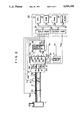
FIG. 2 is a constructional diagram of an embodiment of the invention;
FIG. 3 is a characteristic diagram of a detection signal of an O2 sensor;
FIG. 4 is a block diagram for explaining the operation of an air-fuel control in the embodiment;
FIGS. 5 and 7 are block diagrams for explaining the operation of the embodiment;
FIG. 6 is a characteristic diagram of a purification factor of a 3-component catalytic converter;
FIGS. 8 and 9 are timing charts of the embodiment;
FIG. 10 is a timing chart of another embodiment; and
FIG. 11 is a flowchart for explaining the operation of another embodiment.
DESCRIPTION OF THE PREFERRED EMBODIMENTS
To further clarify a construction of the invention described above, an air-fuel ratio control apparatus for an engine as a preferred embodiment of the invention will be described hereinbelow. FIG. 2 is a schematic constructional diagram showing an engine 10 whose air-fuel ratio is controlled and its peripheral apparatuses. As shown in the diagram, in the embodiment, an ignition timing Ig of an engine 10 and a fuel injection amount TAU are controlled by an electronic control unit (ECU) 20.
As shown in FIG. 2, the engine 10 is of a spark ignition type of four cylinders and four cycles. An intake air is sucked into each cylinder from the upstream through an air cleaner 11, an intake pipe 12, a throttle valve 13, a surge tank 14, and an intake branch pipe 15. On the other hand, a fuel is fed with a pressure from a fuel tank (not shown) and is injected and supplied from fuel injection valves 16a, 16b, 16c, and 16d provided for the intake branch pipe 15. On the other hand, the engine 10 has: a distributor 19 for distributing an electric signal of a high voltage which is supplied from an ignition circuit 17 to spark plugs 18a, 18b, 18c, and 18d of the cylinders; a rotational speed sensor 30, provided in the distributor 19, for detecting a rotational speed Ne of the engine 10; a throttle sensor 31 for detecting an opening degree TH of the throttle valve 13; an intake pressure sensor 32 for detecting an intake pressure PM on the downstream side of the throttle valve 13; a warming-up sensor 33 for detecting a temperature Thw of cooling water of the engine 10; and an intake temperature sensor 34 for detecting a temperature Tam of intake air. The rotational speed sensor 30 is provided so as to face a ring gear which rotates synchronously with a crank shaft of the engine 10. The sensor 30 outputs 24 pulse signals per rotation, that is, 720° CA of the engine 10 in proportion to the rotational speed Ne. The throttle sensor 31 outputs not only an analog signal corresponding to the throttle opening degree TH but also an on/off signal from an idle switch to detect that the throttle valve 13 is almost fully closed.
Further, an exhaust pipe 35 of the engine 10 has therein a 3-component catalytic converter 38 to reduce harmful components (CO, HC, NOx, and the like) contained in the exhaust gas which is exhausted from the engine 10. In addition, an air-fuel ratio sensor 36 as a first oxygen concentration sensor for outputting a linear detection signal according to an air-fuel ratio λ of the mixture gas supplied to the engine 10 is provided on the upstream side of the 3-component catalytic converter 38. An O2 sensor 37 as a second oxygen concentration sensor for outputting a detection signal indicating whether the air-fuel ratio λ of the mixture gas supplied to the engine 10 is rich or lean as compared with a stoichiometric air-fuel ratio λ0 is provided on the downstream side of the 3-component catalytic converter 38.
The ECU 20 is constructed as an arithmetic logic operation circuit mainly comprising well-know components such as CPU 21, ROM 22, RAM 23, backup RAM 24, and the like. The ECU 20 is mutually connected through a bus 27 to an input port 25 for inputting detection signals from the sensors, an output port 26 to output control signals to actuators, and the like. The ECU 20 receives through the input port 25 the signals indicative of the intake pressure PM, intake temperature Tam, throttle opening degree TH, cooling water temperature Thw, air-fuel ratio λ, rotational speed Ne, and the like. Then, the ECU 20 calculates the fuel injection amount TAU and the ignition timing Ig on the basis of those information and outputs control signals to the fuel injection valves 16a to 16d and the ignition circuit 17 through the output port 26. Among the above controls, the air-fuel ratio control will now be described hereinbelow.
The ECU 20 has previously been designed by the following method in order to execute the air-fuel ratio control. The designing method, which will be explained hereinbelow, is disclosed in JP-A-64-110853.
1 Modeling of an object to be controlled
In the embodiment, as a model of a system to control the air-fuel ratio λ of the engine 10, an autoregressive moving average model of degree 1 having a vain time P=3 is used and is, further, approximated in consideration of a disturbance d.
First, the model of the system for controlling the air-fuel ratio λ using the autoregressive moving average model can be approximated by
λ(k)=a·λ(k-1)+b·FAF(k-3)   (1)
where,
λ: air-fuel ratio
FAF: air-fuel ratio correction coefficient
a, b: constants
k: variable indicative of the number of control times from the start of the first sampling
Further, when considering the disturbance d, the model of the control system can be approximated by ##EQU1##
For the models which were approximated as mentioned above, it is easily possible to obtain the constants a and b by a discretion by the rotational synchronous (360° CA) sampling using a step response, that is, to obtain a transfer function G of the system to control the air-fuel ratio λ.
2 Display method of a state variable amount X
By rewriting the above equation (2) by using the state variable amount X(k)=[X1 (k), X2 (k), X3 (k), X4 (k)]T, following equation (3) is obtained. ##EQU2##
Then, we have ##EQU3##
3 Designing of a regulator
A regulator is designed with respect to the above equations (5) and (6). An optimum feedback gain K=[K1, K2, K3, K4 ] and the state variable amount XT (k)=[λ(k), FAF(k-3), FAF(k-2), FAF(k-1)] are used, so that ##EQU4## is obtained. Further, an integration term ZI (k) to absorb errors is added. ##EQU5## Due to this, the air-fuel ratio λ and the correction coefficient FAF can be obtained.
The integration term ZI (k) is a value which is determined by a deviation between a target air-fuel ratio λTG and an actual air-fuel ratio λ(k) and by an integration constant Ka and is obtained by the following equation (7).
Z.sub.I (k)=Z.sub.I (k-1)+Ka·(λ.sub.TG -λ(k)) (7)
FIG. 4 is a block diagram of a system to control the air-fuel ratio λ by which the model was designed as mentioned above. In FIG. 4, the Z-1 transformation has been used to derive the air-fuel ratio correction coefficient FAF(k) from FAF(k-1) and the FAF(k) has been displayed. For this purpose, the past air-fuel ratio correction coefficient FAF(k-1) is stored into the RAM 23 and is read out at the next control timing and is used.
On the other hand, a block P1 surrounded by an alternate long and short dash line in FIG. 4 corresponds to a portion to decide the state variable amount X(k) in a state in which the air-fuel ratio λ(k) is feedback controlled to the target air-fuel ratio λTG. A block P2 corresponds to a portion (accumulating portion) to obtain the integration term ZI (k). A block P3 corresponds to a portion to calculate the present air-fuel ratio correction coefficient FAF(k) from the state variable amount X(k) which was determined in the block P1 and the integration term ZI (k) which was obtained in the block P2.
4 Determination of the optimum feedback gain K and the integration constant Ka
For instance, the optimum feedback gain K and the integration constant Ka can be set by minimizing an evaluation function J which is shown by the following equation. ##EQU6##
The evaluation function J intends to minimize the deviation between the actual air-fuel ratio λ(k) and the target air-fuel ratio λTG while restricting the motion of the air-fuel ratio correction coefficient FAF(k). A weighting of the restriction to the air-fuel ratio correction coefficient FAF(k) can be changed by the values of weight parameters Q and R. Therefore, it is sufficient to determine the optimum feedback gain K and the integration constant Ka by repeating simulations until the optimum control characteristics are obtained by variably changing the values of the weight parameters Q and R.
Further, the optimum feedback gain K and the integration constant Ka depend on the model constants a and b. Therefore, to assure the stability (robust performance) of the system for a fluctuation (parameter fluctuation) of the system to control the actual air-fuel ratio λ it is necessary to design the optimum feedback gain K and the integration constant Ka in consideration of fluctuation amounts of the model constants a and b. Accordingly, the simulations are executed in consideration of the fluctuations of the model constants a and b which can be actually caused, thereby deciding the optimum feedback gain K and the integration constant Ka which satisfy the stability.
Although 1 the modeling of an object to be controlled, 2 the display method of the state variable amount, 3 the designing of the regulator, and 4 the determination of the optimum feedback gain and the integration constant have been described above, they are predetermined. The ECU 20 executes the control by using the results of them, that is, only the equations (6) and (7).
The air-fuel ratio control will now be described hereinbelow with reference to flowcharts shown in FIGS. 5 and 7.
FIG. 5 shows a process to set the fuel injection amount TAU which is executed synchronously with the rotation (every 360° CA).
First, in step 101, a fundamental fuel injection amount Tp is calculated on the basis of the intake pressure PM, rotational speed Ne, and the like. In step 102, a check is made to see if the feedback conditions of the air-fuel ratio λ are satisfied or not. The feedback conditions are such that the cooling water temperature Thw is equal to or higher than a predetermined value and a load and a rotational speed are not high as is well known. If the feedback conditions of the air-fuel ratio λ are not satisfied in step 102, the air-fuel ratio correction coefficient FAF is set to 1 in step 103. Then, step 106 follows.
On the other hand, if the feedback conditions of the air-fuel ratio λ are satisfied in step 102, the target air-fuel ratio λTG is set in step 104 (which will be explained in detail hereinlater). In step 105, the air-fuel ratio correction coefficient FAF is set so that the air-fuel ratio λ is equal to the target air-fuel ratio λTG. In detail, the air-fuel ratio correction coefficient FAF is calculated by the equations (6) and (7) in accordance with the target air-fuel ratio λTG and the air-fuel ratio λ(k) which is detected by the air-fuel ratio sensor 36.
In step 106, a fuel injection amount is corrected for the fundamental fuel injection amount Tp by the following equation in accordance with the air-fuel ratio correction coefficient FAF and another correction coefficient FALL, so that the fuel injection amount TAU is set.
TAU=FAF×T.sub.p ×FALL
An operation signal according to the fuel injection amount TAU which was set as mentioned above is output to the fuel injection valves 16a to 16d.
The setting of the target air-fuel ratio λTG (step 104 in FIG. 5) will now be described.
First, a center value λTGC of the target air-fuel ratio is set on the basis of the detection signal of the O2 sensor 37 so as to correct a deviation between the actual air-fuel ratio and the detection signal of the air-fuel ratio sensor 36. In detail, when the detection signal of the O2 sensor 37 indicates the rich state, the center value λTGC is set to a value on the lean side by only a predetermined value λM. On the contrary, when the detection signal of the O2 sensor 37 indicates the lean state, the center value λTGC is set to a value on the rich side by only the predetermined value λM. FIG. 6 shows characteristics of a purification factor η of the 3-component catalytic converter 38 to the air-fuel ratio λ. As will be explained hereinlater, the air-fuel ratio is controlled within a range of a catalyst window W (hatched portion in the diagram) shown in FIG. 6. Since the catalyst window W is about 0.1%, the above predetermined value λM is set to be smaller than the value of W.
On the other hand, the deviation between the actual air-fuel ratio and the detection signal of the air-fuel ratio sensor also differs depending on the rotational speed Ne and the intake pressure PM. That is, the air-fuel ratio at which the maximum purification factor η is obtained differs depending on the rotational speed Ne and the intake pressure PM. Therefore, an air-fuel ratio at which the maximum purification factor η is obtained is previously derived as an initial value of the center value λTGC by the rotational speed Ne and the intake pressure PM and is stored into the ROM 22. It is sufficient to read out such an air-fuel ratio from the ROM 22 at the start of the feedback control. The initial value of the center value λTGC has characteristics such that it is set to a value on the rich side as the rotational speed Ne and the intake pressure PM increase.
For the center value λTGC which is set as mentioned above, the target air-fuel ratio λTG is changed (dither control) periodically (dither period of TDZA) at a predetermined amplitude (dither amplitude) λDZA within a range of the catalyst window W. With respect to the dither amplitude λDZA and the either period TDZA as well, the optimum value at which the maximum purification factor η is obtained differs depending on the rotational speed Ne and the intake pressure PM. Therefore, the optimum values of the dither amplitude λDZA and the dither period TDZA are previously obtained on the basis of the rotational speed Ne and the intake pressure PM and stored into the ROM 22. It is sufficient to sequentially read out those optimum values from the ROM 22.
The setting of the target air-fuel ratio λTG will now be described with reference to a flowchart shown in FIG. 7.
In the processes in steps 201 to 203, the center value λTGC of the target air-fuel ratio mentioned above is set. First, in step 201, a check is made to see if the detection signal from the O2 sensor 37 indicates the rich state or the lean state. If the detection signal from the O2 sensor 37 indicates the rich state, the center value λTGC is increased by only the predetermined value λM in step 202, that is, it is set to a value on the lean side (λTGC ←λTGCM). On the other hand, in step 201, if the detection signal from the O2 sensor 37 indicates the lean state, the center value λTGC is decreased by only the predetermined value λM in step 203, that is, it is set to a value on the lean side (λTGC ←λTGCM).
The processes in steps 204 to 213 relate to the foregoing dither control. In step 204, a check is made to see if a count value of a counter CDZA is equal to or larger than the dither period TDZA or not. The counter CDZA counts the dither period TDZA. If the count value of the counter CDZA is less than the dither period TDZA, the counter CDZA is counted up (CDZA←CDZA+1) in step 205. Then, step 213 follows.
On the other hand, if the count value of the counter CDZA is equal to or larger than the dither period TDZA in step 204, processes to change the target air-fuel ratio λTG step by step are executed in steps 206 to 212. First, in step 206, the counter CDZA is reset (CDZA=0). The dither amplitude λDZA is set in step 207. In detail, as mentioned above, as a dither amplitude λDZA, the optimum value corresponding to the rotational speed Ne and the intake pressure PM is previously obtained and stored into the ROM 22 as a two-dimensional map of the rotational speed Ne and the intake pressure PM. The dither amplitude λDZA is sequentially read out from the ROM 22. In the next step 208, the dither period TDZA is set. With respect to the dither period TDZA as well, in a manner similar to the dither amplitude λDZA, the optimum value is stored into the ROM 22 as a two-dimensional map of the rotational speed Ne and the intake pressure PM. The dither period TDZA is sequentially read out from the ROM 22.
In step 209, a check is made to see if a flag XDZR has been set or not. If the flag XDZR has been set (XDZR=1), this means that the target air-fuel ratio λTG has been set to a value on the rich side for the center value λTGC. If it is determined in step 209 that the flag XDZR has been set (XDZR=1), that is, if the target air-fuel ratio λTG has been set to a value on the rich side for the center value λTGC until the preceding control timing, in step 210, the flag XDZR is reset (XDZR←0) so that the target air-fuel ratio λTG is set to a value on the lean side by only the dither amplitude λDZA for the center value λTGC. On the other hand, if it is decided in step 209 that the flag XDZR has been reset (XDZR=0), that is, if the target air-fuel ratio λTG has been set to a value on the lean side for the center value λTGC until the preceding control timing, in step 211, the flag XDZR is set (XDZR←1) so that the target air-fuel ratio λTG is set to a value on the rich side by only the dither amplitude λDZA for the center value λTGC. In the next step 212, the dither amplitude λDZA is set to a negative value and step 213 follows.
In step 213, the target air-fuel ratio λTG is set by the following equation.
λ.sub.TG =λ.sub.TGC +λ.sub.DZA
Therefore, in the case where the target air-fuel ratio λTG is set to a value on the lean side by only the dither amplitude λDZA for the center value λTGC, the target air-fuel ratio λTG is set by the following equation in step 213.
λ.sub.TG =λ.sub.TGC +λ.sub.DZA
On the other hand, in the case of setting the target air-fuel ratio λTG to a value on the rich side by only the dither amplitude λDZA for the center value λTGC, since the dither amplitude λDZA is set to a negative value in step 212, the target air-fuel ratio λTG is set by the following equation in step 213.
λ.sub.TG =λ.sub.TGC -λ.sub.DZA
A timing chart in the setting of the center value λTGC mentioned above is shown. For a period of time when the detection signal of the O2 sensor 37 indicates the lean state, the center value λTGC is set to a value on the rich side by the predetermined value λM at a time. For a period of time when the detection signal of the O2 sensor 37 indicates the rich state, the center value λTGC is set to a value on the lean side by the predetermined value λM at a time. Therefore, the center value λTGC is set to the stoichiometric air-fuel ratio shown by the air-fuel ratio sensor 36. Thus, the deviation between the actual air-fuel ratio and the detection signal of the air-fuel ratio sensor 36 can be corrected.
FIG. 9 shows a timing chart regarding the dither control. The target air-fuel ratio λTG is changed and set to a value on the rich or lean side by only the dither amplitude λDZA for the center value λTGC at the short dither period TDZA. Therefore, the purification factor η of the 3-component catalytic converter 38 can be raised.
The characteristics of the detection signal in the case where the O2 sensor 37 is arranged on the downstream side of the 3-component catalytic converter 38 are shown in (b) in FIG. 3. As will be obviously understood from the characteristic diagram, according to the characteristics ((b) in FIG. 3) of the detection signal in the case where the O2 sensor 37 is arranged on the downstream side of the 3-component catalytic converter 38, the rich/lean inverting period is longer than that in the characteristics ((a) in FIG. 3) of the detection signal in the case where the O2 sensor 37 is arranged on the upstream side of the 3-component catalytic converter 38. This is because the harmful components in the exhaust gas are purified by the 3-component catalytic converter 38 by the oxidation-reduction reaction. Therefore, even if a control is executed so that the air-fuel ratio λ is repetitively set to the rich and lean values at a short period in order to raise the purification factor η of the 3-component catalytic converter 38, the air-fuel ratio sensor 36 can be accurately corrected without being influenced by such a control.
On the other hand, since the exhaust gas is sufficiently mixed on the downstream side of the 3-component catalytic converter 38, the detection signal of the air-fuel sensor 36 indicates the average air-fuel ratio λ of all of the cylinders without depending on the air-fuel ratio λ of the special cylinder. Consequently, the air-fuel ratio λ can be properly corrected.
Further, since the exhaust gas is cooled by the 3-component catalytic converter 38 and the copper component in the exhaust gas is also absorbed, deterioration of the O2 sensor 37 can be prevented.
In the above embodiment, the center value λTGC of the target air-fuel ratio is always set in accordance with the detection signal of the O2 sensor 37. Therefore, it is also possible to set the center value λTGC of the target air-fuel ratio to a predetermined value at a time point when the time of the rich state of the detection signal of the O2 sensor 37 and the time of the lean state are almost equal and to stop the setting of the center value after that. In this case, the center value λTGC of the target air-fuel ratio can be set to a point D in FIG. 9 or to an average value of points A, B, C, and D.
On the other hand, in the above embodiment, the center value λTGC of the target air-fuel ratio has been set in accordance with the detection signal of the O2 sensor at each control timing. However, as another embodiment, the center value λTGC of the target air-fuel ratio can be also set in accordance with the time of the rich state and the time of the lean state at a predetermined period of the detection signal of the O2 sensor.
Another embodiment will now be described hereinbelow. As mentioned above, the target air-fuel ratio λTG is set and controlled so as to repeat the rich/lean values at a short period. If the center value λTGC of the target air-fuel ratio is equal to a stoichiometric air-fuel ratio λ0 (14.7) (λTGC0), the detection signal of the O2 sensor 37 is as shown in (a) in FIG. 10. That is, a total time STR of times TRi of the rich state at a predetermined period of the detection signal is equal to a total time STL of times TLi of the lean state. That is,
ST.sub.R =ST.sub.L
where, ##EQU7##
On the other hand, if the center value λTGC of the target air-fuel ratio is rich for the stoichiometric air-fuel ratio λ0TGC0), the times TRi of the rich state are longer than the times TLi of the lean state as shown in (b) in FIG. 10. That is,
ST.sub.R >ST.sub.L
On the other hand, if the center value λTGC of the target air-fuel ratio is lean for the stoichiometric air-fuel ratio λ0TGC0), the times TLi of the lean state are longer than the times TRi of the rich state as shown in (c) in FIG. 10. That is,
ST.sub.R <ST.sub.L
Explanation will now be made with reference to a flowchart shown in FIG. 11. FIG. 11 is substantially similar to FIG. 7 except that only steps 301 to 303 are provided in place of steps 201 to 203 in FIG. 7. Therefore, the descriptions of the similar processes are omitted here.
First, in step 301, the total time STR of the times of the rich state and the total time STL of the times of the lean state for a predetermined period (for example, five periods in the embodiment) of the detection signal of the O2 sensor are compared. The total times STR and STL of the rich/lean states are obtained by a routine which is activated synchronously with the inversion of the detection signal from the O2 sensor 37. That is, a period of time from the preceding activation to the present activation is calculated and the resultant time is added to the total time STR or STL in accordance with the result of discrimination regarding whether such a time relates to the rich time or the lean time, so that the total times STR and STL can be obtained. If STR >STL in step 301, this means that the center value λTGC is rich for the stoichiometric air-fuel ratio λ0, so that the center value λTGC is increased by only the predetermined value λMTGC ←λTGCM) in step 302.
On the other hand, if STR >STL in step 301, this means that the center value λTGC of the target air-fuel ratio is lean for the stoichiometric air-fuel ratio. Therefore, the center value λTGC of the target air-fuel ratio is reduced by only the predetermined value λM in step 303 (λTGC ←λTGCM).
The setting of the center value λTGC of the target air-fuel ratio is finished as mentioned above.
As described in detail above, according to the invention, the air-fuel ratio of the mixture gas is controlled so as to become a stoichiometric air-fuel ratio in accordance with the first detection signal which is output from the first oxygen concentration sensor arranged on the upstream side of the catalyst and the target air-fuel ratio. The target air-fuel ratio is set in accordance with the second detection signal which is output from the second oxygen concentration sensor arranged on the downstream side of the catalyst so as to correct a deviation between the actual air-fuel ratio and the first detection signal.
Therefore, there are excellent effects such that the deviation between the actual air-fuel ratio and the first detection signal can be accurately corrected and the air-fuel ratio can be accurately controlled to the air-fuel ratio of a high purification factor of the catalyst.

Claims (12)

We claim:
1. An air-fuel ratio control apparatus for an engine, comprising:
a catalyst, arranged in an exhaust pipe of the engine, for purifying an exhaust gas;
a first oxygen concentration sensor, arranged in an exhaust pipe of an engine, for outputting a first linear detection signal for an air-fuel ratio of a mixture gas supplied to the engine;
a second oxygen concentration sensor, arranged on a downstream side of a catalyst to purify an exhaust gas which is exhausted from the engine, for outputting a second detection signal according to whether the air-fuel ratio is rich or lean for a stoichiometric air-fuel ratio;
target air-fuel ratio setting means for setting a target air-fuel ratio in accordance with the second detection signal; and
fuel injection amount setting means for setting a fuel injection amount which is supplied to the engine in accordance with the first detection signal and the target air-fuel ratio.
2. An apparatus according to claim 1, wherein the target air-fuel ratio setting means comprises:
operating state detecting mean for detecting an operating state of the engine;
sub-target air-fuel ratio setting means for setting a target air-fuel ratio in accordance with the operating state; and
target air-fuel ratio correcting means for correcting the target air-fuel ratio in accordance with the second detection signal.
3. An apparatus according to claim 2, wherein the sub-target air-fuel ratio setting means has target air-fuel ratio memory means for storing an air-fuel ratio at which a maximum purification factor of the catalyst is obtained as a target air-fuel ratio every said operating state.
4. An apparatus according to claim 2, wherein the target air-fuel ratio correcting means has first target air-fuel ratio correcting means for correcting in a manner such that the target air-fuel ratio gradually changes to a lean side by a predetermined amount at a time in the case where the second detection signal indicates a rich state and that the target air-fuel ratio gradually changes to a rich side by a predetermined amount at a time in the case where the second detection signal indicates a lean state.
5. An apparatus according to claim 2, wherein the target air-fuel ratio correcting means comprises:
total rich time detecting means for detecting a total rich time of the second detection signal in a predetermined period of time;
total lean time detecting means for detecting a total lean time of the second detection signal in the predetermined period of time; and
second target air-fuel ratio correcting means for correcting in a manner such that the target air-fuel ratio gradually changes to a lean side by a predetermined amount at a time in the case where the total rich time is longer than the total lean time and that the target air-fuel ratio gradually changes to a rich side by a predetermined amount at a time in the case where the total lean time is longer than the total rich time.
6. An apparatus according to claim 2, wherein the target air-fuel ratio setting means has target air-fuel ratio resetting means for resetting a value which periodically changes with a predetermined amplitude with respect to the target air-fuel ratio which was corrected by the target air-fuel ratio correcting means as a center into the target air-fuel ratio.
7. An apparatus according to claim 6, wherein the target air-fuel ratio resetting means has predetermined amplitude memory means for storing the predetermined amplitude at which the maximum purification factor of the catalyst is obtained every said operating state.
8. An air-fuel ratio control apparatus for an engine, comprising:
a catalyst, arranged in an exhaust pipe of the engine, for purifying an exhaust gas;
a first oxygen concentration sensor, arranged in an exhaust pipe of an engine, for outputting a first linear detection signal for an air-fuel ratio of a mixture gas supplied to the engine;
a second oxygen concentration sensor, arranged on a downstream side of a catalyst to purify an exhaust gas which is exhausted from the engine, for outputting a second detection signal according to whether the air-fuel ratio is rich or lean for a stoichiometric air-fuel ratio;
operating state detecting means for detecting an operating state of the engine;
initial value setting means for setting an initial value of a target air-fuel ratio in accordance with the operating state;
target air-fuel ratio correcting means for correcting the target air-fuel ratio in accordance with the second detection signal every predetermined period; and
fuel injection amount setting means for setting a fuel injection amount which is supplied to the engine in accordance with the first detection signal and the target air-fuel ratio.
9. An apparatus according to claim 8, wherein the initial value setting means has initial value memory means for storing an air-fuel ratio at which a maximum purification factor of the catalyst is obtained as an initial value every said operating state.
10. An apparatus according to claim 9, wherein the fuel injection amount setting means comprises:
fundamental fuel injection amount setting means for setting a fundamental fuel injection amount in accordance with the operating state; and
air-fuel ratio correction amount setting means for setting an air-fuel ratio correction amount in accordance with the first detection signal and the target air-fuel ratio.
11. An apparatus according to claim 10, wherein the air-fuel ratio correction amount setting means comprises:
state variable amount detecting means for detecting a state variable amount in accordance with the first detection signal and the air-fuel ratio correction amount which was set at a past control timing;
integration value calculating means for calculating an integration value of a deviation between the first detection signal and the target air-fuel ratio; and
air-fuel ratio correction amount calculating means for calculating the air-fuel ratio correction amount in accordance with the state variable amount and the integration value.
12. An apparatus according to claim 11, wherein the air-fuel ratio correction amount calculating means has constant memory means for storing an optimum feedback gain and an integration constant which have been preset so that the engine exhibits a desired operation on the basis of a dynamic model of the engine.
US07/626,829 1989-12-14 1990-12-13 Apparatus for controlling air-fuel ratio for engine Expired - Lifetime US5090199A (en)

Applications Claiming Priority (2)

Application Number Priority Date Filing Date Title
JP1324291A JP2765136B2 (en) 1989-12-14 1989-12-14 Air-fuel ratio control device for engine
JP1-324291 1989-12-14

Publications (1)

Publication Number Publication Date
US5090199A true US5090199A (en) 1992-02-25

Family

ID=18164170

Family Applications (1)

Application Number Title Priority Date Filing Date
US07/626,829 Expired - Lifetime US5090199A (en) 1989-12-14 1990-12-13 Apparatus for controlling air-fuel ratio for engine

Country Status (4)

Country Link
US (1) US5090199A (en)
JP (1) JP2765136B2 (en)
KR (1) KR0137133B1 (en)
DE (1) DE4039876B4 (en)

Cited By (29)

* Cited by examiner, † Cited by third party
Publication number Priority date Publication date Assignee Title
US5255662A (en) * 1991-12-03 1993-10-26 Nissan Motor Company, Ltd. Engine air-fuel ratio controller
US5315823A (en) * 1991-02-12 1994-05-31 Nippondenso Co., Ltd. Control apparatus for speedily warming up catalyst in internal combustion engine
US5339627A (en) * 1991-08-31 1994-08-23 Abb Patent Gmbh Method and apparatus for regulating and testing
US5343701A (en) * 1991-09-24 1994-09-06 Nippondenso Co., Ltd. Air-fuel ratio control system for internal combustion engine
US5375416A (en) * 1993-01-21 1994-12-27 Honda Giken Kogyo Kabushiki Kaisha Air-fuel ratio sensor deterioration-detecting device for internal combustion engines
US5379591A (en) * 1993-01-29 1995-01-10 Honda Giken Kogyo Kabushiki Kaisha Air-fuel ratio control system for internal combustion engines
US5386695A (en) * 1993-01-21 1995-02-07 Honda Giken Kogyo Kabushiki Kaisha Air-fuel ratio control system for internal combustion engines, having catalytic converter deterioration-detecting function
US5390489A (en) * 1992-10-13 1995-02-21 Niopondenso Co., Ltd. Air-fuel ratio control system for internal combustion engine
US5394691A (en) * 1993-02-26 1995-03-07 Honda Giken Kogyo K.K. Air-fuel ratio control system for internal combustion engines having a plurality of cylinder groups
US5400592A (en) * 1993-02-12 1995-03-28 Hitachi, Ltd. Diagnostic apparatus for catalytic converter of an internal combustion engine
US5473889A (en) * 1993-09-24 1995-12-12 Honda Giken Kogyo K.K. (Honda Motor Co., Ltd. In English) Air-fuel ratio control system for internal combustion engines
US5487270A (en) * 1992-07-03 1996-01-30 Nippondenso Co., Ltd. Air-fuel ratio control system for internal combustion engine
US5491975A (en) * 1992-07-03 1996-02-20 Nippondenso Co., Ltd. Air-fuel ratio control system for internal combustion engine
US5610321A (en) * 1994-03-25 1997-03-11 Mazda Motor Corporation Sensor failure detection system for air-to-fuel ratio control system
US5615550A (en) * 1992-05-19 1997-04-01 Honda Giken Kogyo Kabushiki Kaisha Air-fuel ratio control system for internal combustion engines
US5622047A (en) * 1992-07-03 1997-04-22 Nippondenso Co., Ltd. Method and apparatus for detecting saturation gas amount absorbed by catalytic converter
EP0816658A2 (en) * 1996-06-25 1998-01-07 Honda Giken Kogyo Kabushiki Kaisha Air/fuel ratio control system for an internal combustion engine
US5730111A (en) * 1995-06-15 1998-03-24 Nippondenso Co., Ltd. Air-fuel ratio control system for internal combustion engine
US5784879A (en) * 1995-06-30 1998-07-28 Nippondenso Co., Ltd. Air-fuel ratio control system for internal combustion engine
US5806306A (en) * 1995-06-14 1998-09-15 Nippondenso Co., Ltd. Deterioration monitoring apparatus for an exhaust system of an internal combustion engine
US5832724A (en) * 1995-01-27 1998-11-10 Mazda Motor Corporation Air-fuel ratio control system for engines
US6085518A (en) * 1997-09-02 2000-07-11 Denso Corporation Air-fuel ratio feedback control for engines
US6513321B2 (en) * 1999-12-28 2003-02-04 Honda Giken Kogyo Kabushiki Kaisha Exhaust gas purifying apparatus for internal combustion engine
US6539707B2 (en) 2000-10-03 2003-04-01 Denso Corporation Exhaust emission control system for internal combustion engine
US6567738B2 (en) 2001-01-30 2003-05-20 Ford Global Technologies, Llc Fueling control system
US20050284132A1 (en) * 2004-03-05 2005-12-29 Imad Makki Engine control system with mixed exhaust gas oxygen sensor types
US20060000200A1 (en) * 2002-12-30 2006-01-05 Ekkehard Pott Method and device for adjustment of a fuel/air ratio for an internal combustion engine
US20090094962A1 (en) * 2005-12-23 2009-04-16 Robert Bosch Gmbh Method and device for regenerating an emission control system
AU2006203294B2 (en) * 2005-08-31 2011-09-08 Ford Global Technologies, Llc Engine Control System with Mixed Exhaust Gas Oxygen Sensor Types

Families Citing this family (12)

* Cited by examiner, † Cited by third party
Publication number Priority date Publication date Assignee Title
DE4136911A1 (en) * 1991-11-09 1993-05-13 Till Keesmann METHOD FOR CATALYTICALLY COMBUSTION OF THE EXHAUST GASES OF AN INTERNAL COMBUSTION ENGINE EQUIPPED WITH SEVERAL CYLINDERS, AND DEVICE FOR CARRYING OUT THIS METHOD
JP3449011B2 (en) * 1994-05-31 2003-09-22 株式会社デンソー Air-fuel ratio control device for internal combustion engine
US5657735A (en) * 1994-12-30 1997-08-19 Honda Giken Kogyo Kabushiki Kaisha Fuel metering control system for internal combustion engine
CN1082617C (en) * 1994-12-30 2002-04-10 本田技研工业株式会社 Fuel injection control device for IC engine
US5758490A (en) * 1994-12-30 1998-06-02 Honda Giken Kogyo Kabushiki Kaisha Fuel metering control system for internal combustion engine
DE19505687A1 (en) * 1995-02-20 1996-08-22 Audi Ag Control of fuel-injected IC engine, with exhaust catalyst, in secondary-air mode
JP3841842B2 (en) * 1995-02-24 2006-11-08 本田技研工業株式会社 Control device for internal combustion engine
JP3581737B2 (en) * 1995-02-24 2004-10-27 本田技研工業株式会社 Air-fuel ratio control device for internal combustion engine
US5619976A (en) * 1995-02-24 1997-04-15 Honda Giken Kogyo Kabushiki Kaisha Control system employing controller of recurrence formula type for internal combustion engines
DE19801815A1 (en) * 1998-01-19 1999-07-22 Volkswagen Ag Lean-burn i.c. engine exhaust gas cleaning process
FR2833309B1 (en) * 2001-12-07 2006-01-20 Renault DEVICE FOR REGULATING THE WEALTH OF AN INTERNAL COMBUSTION ENGINE
US7809490B2 (en) * 2007-08-17 2010-10-05 Gm Global Technology Operations, Inc. Phase and frequency error based asymmetrical AFR pulse reference tracking algorithm using the pre-catalyst O2 sensor switching output

Citations (7)

* Cited by examiner, † Cited by third party
Publication number Priority date Publication date Assignee Title
US4027477A (en) * 1976-04-29 1977-06-07 General Motors Corporation Dual sensor closed loop fuel control system having signal transfer between sensors during warmup
JPS5664125A (en) * 1979-10-26 1981-06-01 Matsushita Electric Ind Co Ltd Closed loop fuel injection method
JPS603446A (en) * 1983-06-21 1985-01-09 Mitsubishi Electric Corp Air-fuel ratio controller of engine
JPS60243316A (en) * 1984-05-16 1985-12-03 Nissan Motor Co Ltd Secondary air control device of engine
JPS6183466A (en) * 1984-09-29 1986-04-28 Suzuki Motor Co Ltd Air-fuel ratio control device
JPS6445913A (en) * 1987-08-11 1989-02-20 Mitsubishi Motors Corp Catalyst deterioration diagnosing device for internal combustion engine
JPH01110853A (en) * 1987-10-22 1989-04-27 Nippon Denso Co Ltd Air-fuel ratio controller for internal combustion engine

Family Cites Families (4)

* Cited by examiner, † Cited by third party
Publication number Priority date Publication date Assignee Title
DE2713988A1 (en) * 1977-03-30 1978-10-05 Bosch Gmbh Robert PROCESS AND DEVICE FOR DETERMINING THE PROPORTIONAL PART OF THE FUEL-AIR MIXTURE ADDED TO A COMBUSTION ENGINE
DE3500594C2 (en) * 1985-01-10 1995-08-17 Bosch Gmbh Robert Metering system for an internal combustion engine to influence the operating mixture
JP2801596B2 (en) * 1987-11-05 1998-09-21 日本特殊陶業株式会社 Air-fuel ratio control method
DE3827978A1 (en) * 1987-11-10 1989-05-18 Bosch Gmbh Robert Method and device for continuous lambda control

Patent Citations (7)

* Cited by examiner, † Cited by third party
Publication number Priority date Publication date Assignee Title
US4027477A (en) * 1976-04-29 1977-06-07 General Motors Corporation Dual sensor closed loop fuel control system having signal transfer between sensors during warmup
JPS5664125A (en) * 1979-10-26 1981-06-01 Matsushita Electric Ind Co Ltd Closed loop fuel injection method
JPS603446A (en) * 1983-06-21 1985-01-09 Mitsubishi Electric Corp Air-fuel ratio controller of engine
JPS60243316A (en) * 1984-05-16 1985-12-03 Nissan Motor Co Ltd Secondary air control device of engine
JPS6183466A (en) * 1984-09-29 1986-04-28 Suzuki Motor Co Ltd Air-fuel ratio control device
JPS6445913A (en) * 1987-08-11 1989-02-20 Mitsubishi Motors Corp Catalyst deterioration diagnosing device for internal combustion engine
JPH01110853A (en) * 1987-10-22 1989-04-27 Nippon Denso Co Ltd Air-fuel ratio controller for internal combustion engine

Cited By (35)

* Cited by examiner, † Cited by third party
Publication number Priority date Publication date Assignee Title
US5315823A (en) * 1991-02-12 1994-05-31 Nippondenso Co., Ltd. Control apparatus for speedily warming up catalyst in internal combustion engine
US5339627A (en) * 1991-08-31 1994-08-23 Abb Patent Gmbh Method and apparatus for regulating and testing
US5343701A (en) * 1991-09-24 1994-09-06 Nippondenso Co., Ltd. Air-fuel ratio control system for internal combustion engine
US5473888A (en) * 1991-09-24 1995-12-12 Nippondenso Co., Ltd. Air-fuel ratio control system for internal combustion engine
US5255662A (en) * 1991-12-03 1993-10-26 Nissan Motor Company, Ltd. Engine air-fuel ratio controller
US5615550A (en) * 1992-05-19 1997-04-01 Honda Giken Kogyo Kabushiki Kaisha Air-fuel ratio control system for internal combustion engines
DE4322344B4 (en) * 1992-07-03 2006-02-02 Denso Corp., Kariya Air / fuel ratio control system for an internal combustion engine
US5622047A (en) * 1992-07-03 1997-04-22 Nippondenso Co., Ltd. Method and apparatus for detecting saturation gas amount absorbed by catalytic converter
US5491975A (en) * 1992-07-03 1996-02-20 Nippondenso Co., Ltd. Air-fuel ratio control system for internal combustion engine
US5487270A (en) * 1992-07-03 1996-01-30 Nippondenso Co., Ltd. Air-fuel ratio control system for internal combustion engine
US5390489A (en) * 1992-10-13 1995-02-21 Niopondenso Co., Ltd. Air-fuel ratio control system for internal combustion engine
US5386695A (en) * 1993-01-21 1995-02-07 Honda Giken Kogyo Kabushiki Kaisha Air-fuel ratio control system for internal combustion engines, having catalytic converter deterioration-detecting function
US5375416A (en) * 1993-01-21 1994-12-27 Honda Giken Kogyo Kabushiki Kaisha Air-fuel ratio sensor deterioration-detecting device for internal combustion engines
US5379591A (en) * 1993-01-29 1995-01-10 Honda Giken Kogyo Kabushiki Kaisha Air-fuel ratio control system for internal combustion engines
US5400592A (en) * 1993-02-12 1995-03-28 Hitachi, Ltd. Diagnostic apparatus for catalytic converter of an internal combustion engine
US5394691A (en) * 1993-02-26 1995-03-07 Honda Giken Kogyo K.K. Air-fuel ratio control system for internal combustion engines having a plurality of cylinder groups
US5473889A (en) * 1993-09-24 1995-12-12 Honda Giken Kogyo K.K. (Honda Motor Co., Ltd. In English) Air-fuel ratio control system for internal combustion engines
US5610321A (en) * 1994-03-25 1997-03-11 Mazda Motor Corporation Sensor failure detection system for air-to-fuel ratio control system
US5832724A (en) * 1995-01-27 1998-11-10 Mazda Motor Corporation Air-fuel ratio control system for engines
US5806306A (en) * 1995-06-14 1998-09-15 Nippondenso Co., Ltd. Deterioration monitoring apparatus for an exhaust system of an internal combustion engine
US5730111A (en) * 1995-06-15 1998-03-24 Nippondenso Co., Ltd. Air-fuel ratio control system for internal combustion engine
US5784879A (en) * 1995-06-30 1998-07-28 Nippondenso Co., Ltd. Air-fuel ratio control system for internal combustion engine
EP0816658A2 (en) * 1996-06-25 1998-01-07 Honda Giken Kogyo Kabushiki Kaisha Air/fuel ratio control system for an internal combustion engine
EP0816658A3 (en) * 1996-06-25 1999-12-08 Honda Giken Kogyo Kabushiki Kaisha Air/fuel ratio control system for an internal combustion engine
US6073073A (en) * 1996-06-25 2000-06-06 Honda Giken Kogyo Kabushiki Kaisha Air/fuel ratio control system for an internal combustion engine
US6085518A (en) * 1997-09-02 2000-07-11 Denso Corporation Air-fuel ratio feedback control for engines
US6513321B2 (en) * 1999-12-28 2003-02-04 Honda Giken Kogyo Kabushiki Kaisha Exhaust gas purifying apparatus for internal combustion engine
US6539707B2 (en) 2000-10-03 2003-04-01 Denso Corporation Exhaust emission control system for internal combustion engine
US6567738B2 (en) 2001-01-30 2003-05-20 Ford Global Technologies, Llc Fueling control system
US20060000200A1 (en) * 2002-12-30 2006-01-05 Ekkehard Pott Method and device for adjustment of a fuel/air ratio for an internal combustion engine
US20050284132A1 (en) * 2004-03-05 2005-12-29 Imad Makki Engine control system with mixed exhaust gas oxygen sensor types
US7377104B2 (en) * 2004-03-05 2008-05-27 Ford Global Technologies, Llc Engine control system with mixed exhaust gas oxygen sensor types
AU2006203294B2 (en) * 2005-08-31 2011-09-08 Ford Global Technologies, Llc Engine Control System with Mixed Exhaust Gas Oxygen Sensor Types
US20090094962A1 (en) * 2005-12-23 2009-04-16 Robert Bosch Gmbh Method and device for regenerating an emission control system
US8028519B2 (en) * 2005-12-23 2011-10-04 Robert Bosch Gmbh Method and device for regenerating an emission control system

Also Published As

Publication number Publication date
DE4039876A1 (en) 1991-07-04
JP2765136B2 (en) 1998-06-11
KR910012520A (en) 1991-08-08
DE4039876B4 (en) 2006-08-31
KR0137133B1 (en) 1998-04-25
JPH03185244A (en) 1991-08-13

Similar Documents

Publication Publication Date Title
US5090199A (en) Apparatus for controlling air-fuel ratio for engine
JP4420288B2 (en) Cylinder-by-cylinder air-fuel ratio control apparatus for internal combustion engine
JP4321411B2 (en) Cylinder-by-cylinder air-fuel ratio control apparatus for internal combustion engine
US5243952A (en) Air-fuel ratio control apparatus for use in engine
US5209214A (en) Air fuel ratio control apparatus for engine
US5265575A (en) Apparatus for controlling internal combustion engine
US5784879A (en) Air-fuel ratio control system for internal combustion engine
JPH109022A (en) Air-fuel ratio control device of internal combustion engine
JP3170067B2 (en) Lean combustion control device for internal combustion engine and fuel injection amount control device having the same
US5491975A (en) Air-fuel ratio control system for internal combustion engine
US5638800A (en) Method and apparatus for controlling air-fuel ratio learning of an internal combustion engine
US5158062A (en) Adaptive air/fuel ratio control method
US5390489A (en) Air-fuel ratio control system for internal combustion engine
US5255662A (en) Engine air-fuel ratio controller
US5487270A (en) Air-fuel ratio control system for internal combustion engine
GB2189626A (en) Method of air/fuel ratio control for internal combustion engine
US5033440A (en) Apparatus for controlling air/fuel ratio of internal combustion engine
JPH0617640A (en) Saturated adsorption amount detecting device for catalyst
JP4600699B2 (en) Cylinder-by-cylinder air-fuel ratio control apparatus for internal combustion engine
JP2841806B2 (en) Air-fuel ratio control device for engine
JP2970144B2 (en) Air-fuel ratio control device for internal combustion engine
JPH0756239B2 (en) Basic control variable setting method for internal combustion engine
JP3442216B2 (en) Engine control device
JP3972925B2 (en) Catalyst deterioration detection device for internal combustion engine
JP2631587B2 (en) Fuel supply control device for internal combustion engine

Legal Events

Date Code Title Description
AS Assignment

Owner name: NIPPONDENSO CO., LTD., A CORP. OF JAPAN

Free format text: ASSIGNMENT OF ASSIGNORS INTEREST.;ASSIGNORS:IKUTA, KENJI;KONDO, TOSHIO;HARAGUCHI, HIROSHI;REEL/FRAME:005536/0899

Effective date: 19901205

FEPP Fee payment procedure

Free format text: PAYOR NUMBER ASSIGNED (ORIGINAL EVENT CODE: ASPN); ENTITY STATUS OF PATENT OWNER: LARGE ENTITY

STCF Information on status: patent grant

Free format text: PATENTED CASE

FPAY Fee payment

Year of fee payment: 4

FPAY Fee payment

Year of fee payment: 8

FPAY Fee payment

Year of fee payment: 12