US5099992A - Arrangement in connection with a rack for orderly storage and/or for keeping syringes with a luer tip ready for use - Google Patents

Arrangement in connection with a rack for orderly storage and/or for keeping syringes with a luer tip ready for use Download PDF

Info

Publication number
US5099992A
US5099992A US07/552,122 US55212290A US5099992A US 5099992 A US5099992 A US 5099992A US 55212290 A US55212290 A US 55212290A US 5099992 A US5099992 A US 5099992A
Authority
US
United States
Prior art keywords
rack
luer
bushing
luer cone
syringes
Prior art date
Legal status (The legal status is an assumption and is not a legal conclusion. Google has not performed a legal analysis and makes no representation as to the accuracy of the status listed.)
Expired - Lifetime
Application number
US07/552,122
Inventor
Bent Heimreid
Current Assignee (The listed assignees may be inaccurate. Google has not performed a legal analysis and makes no representation or warranty as to the accuracy of the list.)
Individual
Original Assignee
Individual
Priority date (The priority date is an assumption and is not a legal conclusion. Google has not performed a legal analysis and makes no representation as to the accuracy of the date listed.)
Filing date
Publication date
Application filed by Individual filed Critical Individual
Application granted granted Critical
Publication of US5099992A publication Critical patent/US5099992A/en
Anticipated expiration legal-status Critical
Expired - Lifetime legal-status Critical Current

Links

Images

Classifications

    • AHUMAN NECESSITIES
    • A61MEDICAL OR VETERINARY SCIENCE; HYGIENE
    • A61JCONTAINERS SPECIALLY ADAPTED FOR MEDICAL OR PHARMACEUTICAL PURPOSES; DEVICES OR METHODS SPECIALLY ADAPTED FOR BRINGING PHARMACEUTICAL PRODUCTS INTO PARTICULAR PHYSICAL OR ADMINISTERING FORMS; DEVICES FOR ADMINISTERING FOOD OR MEDICINES ORALLY; BABY COMFORTERS; DEVICES FOR RECEIVING SPITTLE
    • A61J1/00Containers specially adapted for medical or pharmaceutical purposes
    • A61J1/14Details; Accessories therefor
    • A61J1/20Arrangements for transferring or mixing fluids, e.g. from vial to syringe
    • A61J1/2096Combination of a vial and a syringe for transferring or mixing their contents
    • AHUMAN NECESSITIES
    • A61MEDICAL OR VETERINARY SCIENCE; HYGIENE
    • A61BDIAGNOSIS; SURGERY; IDENTIFICATION
    • A61B50/00Containers, covers, furniture or holders specially adapted for surgical or diagnostic appliances or instruments, e.g. sterile covers
    • A61B50/20Holders specially adapted for surgical or diagnostic appliances or instruments
    • A61B50/22Racks
    • AHUMAN NECESSITIES
    • A61MEDICAL OR VETERINARY SCIENCE; HYGIENE
    • A61MDEVICES FOR INTRODUCING MEDIA INTO, OR ONTO, THE BODY; DEVICES FOR TRANSDUCING BODY MEDIA OR FOR TAKING MEDIA FROM THE BODY; DEVICES FOR PRODUCING OR ENDING SLEEP OR STUPOR
    • A61M5/00Devices for bringing media into the body in a subcutaneous, intra-vascular or intramuscular way; Accessories therefor, e.g. filling or cleaning devices, arm-rests
    • A61M5/008Racks for supporting syringes or needles
    • AHUMAN NECESSITIES
    • A61MEDICAL OR VETERINARY SCIENCE; HYGIENE
    • A61JCONTAINERS SPECIALLY ADAPTED FOR MEDICAL OR PHARMACEUTICAL PURPOSES; DEVICES OR METHODS SPECIALLY ADAPTED FOR BRINGING PHARMACEUTICAL PRODUCTS INTO PARTICULAR PHYSICAL OR ADMINISTERING FORMS; DEVICES FOR ADMINISTERING FOOD OR MEDICINES ORALLY; BABY COMFORTERS; DEVICES FOR RECEIVING SPITTLE
    • A61J1/00Containers specially adapted for medical or pharmaceutical purposes
    • A61J1/14Details; Accessories therefor
    • A61J1/20Arrangements for transferring or mixing fluids, e.g. from vial to syringe
    • A61J1/2003Accessories used in combination with means for transfer or mixing of fluids, e.g. for activating fluid flow, separating fluids, filtering fluid or venting
    • A61J1/202Separating means
    • A61J1/2044Separating means having slits
    • AHUMAN NECESSITIES
    • A61MEDICAL OR VETERINARY SCIENCE; HYGIENE
    • A61JCONTAINERS SPECIALLY ADAPTED FOR MEDICAL OR PHARMACEUTICAL PURPOSES; DEVICES OR METHODS SPECIALLY ADAPTED FOR BRINGING PHARMACEUTICAL PRODUCTS INTO PARTICULAR PHYSICAL OR ADMINISTERING FORMS; DEVICES FOR ADMINISTERING FOOD OR MEDICINES ORALLY; BABY COMFORTERS; DEVICES FOR RECEIVING SPITTLE
    • A61J1/00Containers specially adapted for medical or pharmaceutical purposes
    • A61J1/14Details; Accessories therefor
    • A61J1/20Arrangements for transferring or mixing fluids, e.g. from vial to syringe
    • A61J1/2003Accessories used in combination with means for transfer or mixing of fluids, e.g. for activating fluid flow, separating fluids, filtering fluid or venting
    • A61J1/2048Connecting means
    • A61J1/2055Connecting means having gripping means
    • AHUMAN NECESSITIES
    • A61MEDICAL OR VETERINARY SCIENCE; HYGIENE
    • A61JCONTAINERS SPECIALLY ADAPTED FOR MEDICAL OR PHARMACEUTICAL PURPOSES; DEVICES OR METHODS SPECIALLY ADAPTED FOR BRINGING PHARMACEUTICAL PRODUCTS INTO PARTICULAR PHYSICAL OR ADMINISTERING FORMS; DEVICES FOR ADMINISTERING FOOD OR MEDICINES ORALLY; BABY COMFORTERS; DEVICES FOR RECEIVING SPITTLE
    • A61J1/00Containers specially adapted for medical or pharmaceutical purposes
    • A61J1/14Details; Accessories therefor
    • A61J1/20Arrangements for transferring or mixing fluids, e.g. from vial to syringe
    • A61J1/2003Accessories used in combination with means for transfer or mixing of fluids, e.g. for activating fluid flow, separating fluids, filtering fluid or venting
    • A61J1/2048Connecting means
    • A61J1/2058Connecting means having multiple connecting ports

Definitions

  • the invention relates to an arrangement in connection with a rack for orderly storage and/or for keeping of syringes, each with a luer projection ready for use, the rack also comprising receptacle means for the syringes.
  • Syringes are used in all departments of the health sector. Some people inject themselves, e.g. diabetes patients, but in most cases the injection, i.e. the contents of the syringe, are administered by a medical practitioner or a nurse.
  • the patient/user receives the injection either subcutaneously (under the skin), intramuscularly (in the muscle), or intravenously (via the vein system).
  • the syringe contents may be administered by connecting the syringe with an intravenous cannula or by providing the syringe with a syringe needle which is introduced under the skin or into a muscle. Injections may also be administered in spinal/epidural ducts.
  • every object to be used must be sterile.
  • Syringes are filled by sucking the contents of an ampule or another container through a suction cannula.
  • medicament suction may, e.g., be carried out in the patient's home, in separate syringe medicament rooms, in surgical theatres, wards for intensive care, etc.
  • syringes filled with a medicament are e.g. placed on an anaesthetics table.
  • the medicament is administered as required.
  • Use of several different syringes during one anesthetization is not uncommon, and this means that there will be a plurality of syringes, ampulses and needles, etc., in circulation. Conditions may easily become slightly chaotic, since may different medicaments are also used.
  • the hazard of making an error or administering a wrong medicament will increase when syringes, after some time, lie about in a mess, e.g. in an acute situation. This may happen in spite of the fact that each syringe should be marked with the kind of medicament to be administered.
  • syringes As known, use of syringes generally requires the strictest possible hygiene, and the syringe or syringes, thus, must be kept under maximum hygienic conditions and safety against confusion, from the moment they are filled and until they are used.
  • a common procedure today is that a sterile stop or plug is provided on the syringe tip upon the syringe being filled, and if the syringe tip is sterile.
  • the syringe needle is kept in a sterile wrapping until it is to be used.
  • Another procedure is to keep the syringe needle on the syringe, e.g. inserted in the ampule with the medicament to be used.
  • a plurality of equal syringes are often prepared. They are put side-by-side. It is unsatisfactory to have syringes lying about freely, because they may roll about and/or be touched in an undesirable manner, so that sterility is lost. It is even more difficult to maintain necessary hygienic conditions when there are different medicaments to be administered at the same time.
  • Some medicaments are stored for up to 24 hours after having been sucked in a sterile manner into a syringe, with a sterile plug/needle on the tip. This, obviously, does not improve conditions are regards hygiene.
  • One of the known systems used to day, luer plugs are bushing members having a cone shaped portion at one end with a finishing external locking thread. At the other end there is a bushing portion shaped with a slightly larger diameter and an internal locking thread, adapted to the cone shaped locking thread.
  • the cone has a conical blind bore, adapted to the conical shape of the syringe tip, and the bushing member has an internal coaxial conical plug which is adapted, to the conical blind bore in the locking cone.
  • the invention is based on known technology, racks being known for receiving syringes, needles, ampullae, and the like.
  • an arrangement in connection with a rack is, thus, provided for orderly storage and/or for keeping syringes with a luer tip or a luer locking tip ready for use, which rack comprises receptacle means for the syringes.
  • the syringe receptacle means comprise spigots which are integrated in the rack, and bushing members which may be placed on respective spigots.
  • the bushing members are shaped for receiving the luer tips of the syringes.
  • the bushing member may have an inner transversal wall, so that both tip receptacle means are physically separated, or the transveral wall may be omitted, or it may, if desired, have a through hole. It is this open bushing member design which is of special interest, since it may be part of an advantageous transferring system for transferring a dosage of a medicament from one syringe to another mixture of two components/medicaments or for eliminating air.
  • Each bushing member may advantageously at its ends be provided for being locked to a luer thread in a bushing portion of a luer plug.
  • the spigots are provided in one or a plurality of rows on a block, shaped rack.
  • a rack will be steady and compact.
  • An arrangement of the spigots on two (or more) opposite lateral block faces is rendered possible.
  • the rack will, thus, be utilized in the best possible manner and it may be made more universally applicable if spigots are arranged on one lateral block face, whereas spigots and other receptacle means--for needles, ampules and the like--are placed on the opposite lateral block face.
  • the last-mentioned embodiment is a preferred embodiment because it provides for orderly storage and/or for keeping ready syringes with associated needles, ampules, and the like.
  • the filled syringes may, e.g., be placed in one row, whereas associated ampules are placed in a parallel receptacle row.
  • Required syringe needles may also be placed in a parallel row. In this manner good order and survey is achieved.
  • FIG. 1 is a perspective view of a rack embodying principles of the present invention
  • FIG. 2 shows the rack of FIG. 1 as seen from below
  • FIG. 3 is a perspective view of a luer plug
  • FIG. 4 shows a partial section through the plug of FIG. 3
  • FIG. 5 shows a bushing member in a perspective view, for use on the rack of FIGS. 10 and 11,
  • FIG. 6 is a longitudinal section of the bushing member of FIG. 5,
  • FIG. 7 shows a portion of the rack of FIGS. 1 and 2, with a provided bushing member (in section), and with a syringe shown inserted in place in the bushing member,
  • FIG. 8 is a perspective view of the rack
  • FIG. 9 shows two syringes which are connected with the new bushing member according to FIGS. 5 and 6, and
  • FIG. 10 shows two syringes which are connected with a bushing member having a closed transversal wall, and with one syringe being provided with a luer connection,
  • FIG. 11 shows two syringes which are connected with the bushing member according to FIGS. 5 and 6, for mixture of two medicaments
  • FIG. 12 shows two syringes which are connected with the bushing member according to FIGS. 5 and 6, for transfer of medicament from one syringe to the other.
  • Block 1 suitably consists of a sterilizable material, e.g. a suitable plastic material.
  • Block 1 has four lateral block faces, 2, 3, 4, and 5, and two block end faces, 6 and 7.
  • spigot is used herein to denote an axially elongated, peg-like boss, which is preferably externally tapered, e.g., frustoconically tapered, so as to diminish in external diameter from the block face on which it is based, towards a free outer end.
  • Spigots 11 are arranged in a row along the edge, in the present instance, there are six spigots 11. On the opposite face edge, two spigots 12 are placed, one at each block end. In parallel with and inside the row of spigots 11, a row of relatively deep recesses or depressions 9 is provided.
  • a row of slightly more shallow depressions or recesses 8 is provided. Behind the row of depressions 8 there is a row of shallow/deep depressions or recesses 10.
  • the next row comprises depressions or blind bores 8 of varying diameters, in this case increasing towards the right side in FIG. 1, which bores are intended for receiving ampules.
  • Depressions 10 which may be shallow or deep, are intended for receiving other equipment that might be required, e.g. extra ampules, medicament containers, needles, etc.
  • Spigots 11 and 12 are intended for receiving syringes, and the special function of the spigots will be explained in detail below.
  • the luer plug shown in FIGS. 3 and 4 has a locking spigot portion 13 and a bushing portion 14. At the end of the locking spigot a locking thread 15 is provided. The latter is intended for threaded and locking cooperation with an internal thread 16 in a bushing portion 14. Centrally in bushing portion 14, there is a spigot 17 which is slightly conical externally. In locking spigots 13 a corresponding slightly conical bore 18 is provided. The slightly conical bore 18 and the slightly conical spigot 17 are mutually adapted, so that the spigot 17 on a luer plug may be inserted into conical bore 18 in a sealing manner. Slightly conical bore 18 is adapted to a so called luer cone, which is e.g.
  • a syringe tip may be inserted into conical bore 18 for sealing cooperation with the luer plug.
  • Locking thread 15 and internal thread 16 are mutually adapted so that locking spigot 13, 15 on a luer plug may be screwed into and cooperate with thread 16, with internal spigot 17 passing into conical bore 18 of an adjacent plug.
  • Rack side 4 shown in FIG. 2, is especially suitable when a large number of preferably similar syringes is to be prepared for use, e.g. in connection with inocculation. In this case eighteen syringes may be provided in rows in the rack.
  • Associated needles may, if desired, be placed in receptacle bores in block face 4, or they may be placed in a bowl wrapped in a sterile manner until they are to be used.
  • the rack or block 1 When the rack is used as shown in FIGS. 1 and 8, the rack or block 1 rests on spigots 24, and conversely, when the rack is used as shown in FIG. 2, it rests in a stable and steady manner on spigots 11, 12.
  • Spigots 11 and 12 are intend for receiving special bushing members 21, see FIGS. 7 and 8.
  • FIGS. 5 and 6 One such a bushing member 21 is shown in more detail in FIGS. 5 and 6.
  • this special bushing member is an externally ridged 39 circular cylinder, which at each end is provided with a plug receptacle means 40, 41, intended for receiving a form-fitting luer tip or luer cone.
  • Receptacle means 40, 41 are separated by a transversal wall or partition 42.
  • the partition 42 has a throughbore or a through hole 43, but the partition may also be unperforated so that the receptacle means are physically separated. See FIGS. 7 and 8.
  • Bushing member 21 has a flange-shaped locking thread 44, 45 at each end intended for cooperation with a luer thread in a bushing-shaped portion fo a luer plug see, e.g., FIG. 10. In this connection one should also refer to what is mentioned above in regard to luer plugs and the special design of such plugs.
  • FIG. 7 a portion of a rack 1 with spigots 11 is shown.
  • a bushing member 21 On two spigots, a bushing member 21 is provided.
  • One one bushing member 21, shown in longitudinal section, an inserted syringe 46 is indicated.
  • Syringe 46 has a luer tip or cone 47 fitting into receptacle means 40 in the bushing member.
  • spigot 11 is adapted to be receptacle means 41.
  • the spigot as mentioned before, is advantageously shaped like a luer cone, i.e. corresponding to cone 47.
  • a sterile-wrapped bushing member 21 is removed from its wrapping and placed on spigot 11, whereon syringe tip 47 may be inserted into slightly conical receptacle means 40, as shown in FIG. 7. In this manner, the syringe will be kept in the rack in a sterile manner.
  • FIG. 8 shows an example of how rack 1 may be used.
  • a respective bushing member 21 is placed and a syringe 46 is placed in each of members 21.
  • syringe needles 22 and ampules 23, etc. are placed in the recesses or bores.
  • FIG. 1 On what may be called the rack underside in FIG. 1, a total of eighteen spigots 24 is shown. They correspond to spigots 11 and 12 as to shape and function, and are provided for the same reason.
  • Rack side 4 shown in FIG. 2 is especially suitable when a larger number of preferably identical syringes is to be prepared for use, e.g. in connection with inocculation. In this case, eighteen syringes may be placed in rows on the rack.
  • Associated needles may, if desired, be placed in receptacle bores (not shown) in block face 4, or they may be placed in a bowl in their sterile wrappings, ready for use.
  • the rack or block rests on spigots 24, and conversely, when the rack is used as shown in FIG. 2, it will rest in a stable and steady manner on spigots 11, 12.
  • bushing member 21 in the embodiment shown in the sectional view of FIG. 6, in which the internal partition has a through bore may additionaly be utilized as a component in an advantageous manner when it is desirable to transfer a medicament from one syringe to another.
  • Such a connection of two syringes is shown in FIGS. 9-12.
  • a syringe 48 with a syringe tip 49 and a syringe 50 with a syringe tip 51 are shown.
  • the two syrings are connected by the aid of bushing member 21, with one syringe tip 49, as shown, being inserted into receptacle means 40, and the other syringe tip 51 being inserted in conical receptacle means 41.
  • the contents of the syringes may be moved from one syringe to the other and back (FIG. 11) by the aid of plungers 26, 27, and, in addition to a desired transfer, to achieve a more accurate dosage (FIG. 12), the medicaments may also be mixed and air 25 may, obviously, be removed from one syringe by being transferred to the other syringe (FIG. 9).
  • a bushing member with a solid partition 42 may advantageously be used for a closure member for one or two syringes. It will be especially advantageous to use the bushing member for a closure means when the bushing member has a luer locking thread at one or both ends, see FIGS. 5 and 6, whereas the syringe has a bushing-shaped portion about its luer cone, corresponding to the locking bushing portion known from a luer plug.
  • Such a possible embodiment of the syringe is shown in FIG. 10, showing a modified syringe 48 with a luer tip 49 surrounded by an internally threaded bushing portion 54, which corresponds to the bushing portion known from luer plugs. See the above description of a luer plug.
  • Bushing member 21 can then be screwed in place inside bushing-shaped portion 54, with luer thread 44 being screwed into bushing 54. In this manner, the bushing member may be tightened well against cone 49 and is kept in place in its locking/closing position.
  • the bushing member with a tight partition 42 may also, advantageously, be used for all couplings which are surrounded by an internally threaded bushing-shaped portion 54.

Abstract

A block-shaped rack has a plurality of pairs of opposite faces. At least two opposite faces are provided with outwardly projecting, peg-like luer cone tip replicas. A plurality of bushings is provided, each having two axially oppositely opening luer cone receptacle replicas. In use, luer cone-tipped syringes can be removably mounted on the rack using the bushings as adapters. The bushings may be supplied packaged in a sterile condition. If the receptacles on a bushing are intercommunicated within the bushing, the bushing may act as an adapter for two syringes, so that fluid can be transferred from one to the other.

Description

BACKGROUND OF THE INVENTION
The invention relates to an arrangement in connection with a rack for orderly storage and/or for keeping of syringes, each with a luer projection ready for use, the rack also comprising receptacle means for the syringes.
Syringes are used in all departments of the health sector. Some people inject themselves, e.g. diabetes patients, but in most cases the injection, i.e. the contents of the syringe, are administered by a medical practitioner or a nurse.
The patient/user receives the injection either subcutaneously (under the skin), intramuscularly (in the muscle), or intravenously (via the vein system). The syringe contents (medicament) may be administered by connecting the syringe with an intravenous cannula or by providing the syringe with a syringe needle which is introduced under the skin or into a muscle. Injections may also be administered in spinal/epidural ducts.
In any case, every object to be used must be sterile.
Syringes are filled by sucking the contents of an ampule or another container through a suction cannula. Such medicament suction may, e.g., be carried out in the patient's home, in separate syringe medicament rooms, in surgical theatres, wards for intensive care, etc.
In a surgical theatre, syringes filled with a medicament are e.g. placed on an anaesthetics table. During administration to the patient and maintenance of anesthelization, the medicament is administered as required. Use of several different syringes during one anesthetization is not uncommon, and this means that there will be a plurality of syringes, ampulses and needles, etc., in circulation. Conditions may easily become slightly chaotic, since may different medicaments are also used. The hazard of making an error or administering a wrong medicament will increase when syringes, after some time, lie about in a mess, e.g. in an acute situation. This may happen in spite of the fact that each syringe should be marked with the kind of medicament to be administered.
As known, use of syringes generally requires the strictest possible hygiene, and the syringe or syringes, thus, must be kept under maximum hygienic conditions and safety against confusion, from the moment they are filled and until they are used. A common procedure today is that a sterile stop or plug is provided on the syringe tip upon the syringe being filled, and if the syringe tip is sterile. The syringe needle is kept in a sterile wrapping until it is to be used. Another procedure is to keep the syringe needle on the syringe, e.g. inserted in the ampule with the medicament to be used.
In the course of daily routines filled and ready syringes are kept on a tray or the like in a refrigerator, or on the patient's bedside table, etc. before the injection is administered to the patient. Often, it happens that the syringe is not reposing where it was put, but rolls about on the tray or may even fall onto the floor. Needles and/or tips then often become less than sterile. The syringes have no firm bed and conditions easily get chaotic. The hygienic situation, as mentioned, may also become hazardous.
For inocculation or for administration of injections to many persons, a plurality of equal syringes are often prepared. They are put side-by-side. It is unsatisfactory to have syringes lying about freely, because they may roll about and/or be touched in an undesirable manner, so that sterility is lost. It is even more difficult to maintain necessary hygienic conditions when there are different medicaments to be administered at the same time.
The conventional system as regards storage of syringes with medicaments, from the moment the syringe is filled with the medicament and until the latter is administered, is thus not satisfactory. There is a hazard of sterility being lost, since routines do not comprise a firm and/or steady holder for the syringes. There is a hazard of administrating a wrong medicament and/or a wrong dosis. In acute situations it will often be difficult to take in everything at a glance, e.g. when several filled syringes are placed together in a bowl or the like in a refrigerator. Some medicaments are stored for up to 24 hours after having been sucked in a sterile manner into a syringe, with a sterile plug/needle on the tip. This, obviously, does not improve conditions are regards hygiene. One of the known systems used to day, luer plugs, are bushing members having a cone shaped portion at one end with a finishing external locking thread. At the other end there is a bushing portion shaped with a slightly larger diameter and an internal locking thread, adapted to the cone shaped locking thread. The cone has a conical blind bore, adapted to the conical shape of the syringe tip, and the bushing member has an internal coaxial conical plug which is adapted, to the conical blind bore in the locking cone.
When a medicament is to be sucked into a syringe from an ampule or the like, this is commonly carried out through a suction cannula which is placed onto the syringe tip. When the syringe has been filled, the suction cannula is removed and a sterile luer plug is provided instead. When the medicament is to be administered, the luer plug is removed and the syringe tip is provided with a needle or a cannula.
SUMMARY OF THE INVENTION
It is a main object of the present invention to provide an arrangement, in connection with a rack for orderly storage and/or for keeping syringes ready for use, with the aim of achieving controlled and sterile conditions. Another object of the invention is to provide an arrangement in connection with a rack for orderly storage and/or for keeping syringes, needle, ampules and the like prepared for use.
The invention is based on known technology, racks being known for receiving syringes, needles, ampullae, and the like.
According to the invention an arrangement in connection with a rack is, thus, provided for orderly storage and/or for keeping syringes with a luer tip or a luer locking tip ready for use, which rack comprises receptacle means for the syringes. The syringe receptacle means comprise spigots which are integrated in the rack, and bushing members which may be placed on respective spigots. The bushing members are shaped for receiving the luer tips of the syringes.
The bushing member may have an inner transversal wall, so that both tip receptacle means are physically separated, or the transveral wall may be omitted, or it may, if desired, have a through hole. It is this open bushing member design which is of special interest, since it may be part of an advantageous transferring system for transferring a dosage of a medicament from one syringe to another mixture of two components/medicaments or for eliminating air.
Each bushing member may advantageously at its ends be provided for being locked to a luer thread in a bushing portion of a luer plug.
In a suitable embodiment of the invention, the spigots are provided in one or a plurality of rows on a block, shaped rack. Such a rack will be steady and compact. An arrangement of the spigots on two (or more) opposite lateral block faces is rendered possible. The rack will, thus, be utilized in the best possible manner and it may be made more universally applicable if spigots are arranged on one lateral block face, whereas spigots and other receptacle means--for needles, ampules and the like--are placed on the opposite lateral block face.
The last-mentioned embodiment is a preferred embodiment because it provides for orderly storage and/or for keeping ready syringes with associated needles, ampules, and the like.
The filled syringes may, e.g., be placed in one row, whereas associated ampules are placed in a parallel receptacle row. Required syringe needles may also be placed in a parallel row. In this manner good order and survey is achieved.
BRIEF DESCRIPTION OF THE DRAWINGS
The invention is disclosed in more detail below with reference to the accompanying drawings, in which:
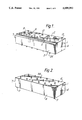
FIG. 1 is a perspective view of a rack embodying principles of the present invention,
FIG. 2 shows the rack of FIG. 1 as seen from below,
FIG. 3 is a perspective view of a luer plug,
FIG. 4 shows a partial section through the plug of FIG. 3,
FIG. 5 shows a bushing member in a perspective view, for use on the rack of FIGS. 10 and 11,
FIG. 6 is a longitudinal section of the bushing member of FIG. 5,
FIG. 7 shows a portion of the rack of FIGS. 1 and 2, with a provided bushing member (in section), and with a syringe shown inserted in place in the bushing member,
FIG. 8 is a perspective view of the rack,
FIG. 9 shows two syringes which are connected with the new bushing member according to FIGS. 5 and 6, and
FIG. 10 shows two syringes which are connected with a bushing member having a closed transversal wall, and with one syringe being provided with a luer connection,
FIG. 11 shows two syringes which are connected with the bushing member according to FIGS. 5 and 6, for mixture of two medicaments, and
FIG. 12 shows two syringes which are connected with the bushing member according to FIGS. 5 and 6, for transfer of medicament from one syringe to the other.
DETAILED DESCRIPTION
The rack shown in FIGS. 1, 2, 7 and 8 is block-shaped. Block 1 suitably consists of a sterilizable material, e.g. a suitable plastic material.
Block 1 has four lateral block faces, 2, 3, 4, and 5, and two block end faces, 6 and 7.
In one lateral block face 2, as shown in FIG. 1, several recesses, 8, 9, and 10 are formed. On the same block face 2 there are also several projecting spigots 11, 12. (The term "spigot" is used herein to denote an axially elongated, peg-like boss, which is preferably externally tapered, e.g., frustoconically tapered, so as to diminish in external diameter from the block face on which it is based, towards a free outer end.)
Spigots 11 are arranged in a row along the edge, in the present instance, there are six spigots 11. On the opposite face edge, two spigots 12 are placed, one at each block end. In parallel with and inside the row of spigots 11, a row of relatively deep recesses or depressions 9 is provided.
In parallel with the row of depressions 9, a row of slightly more shallow depressions or recesses 8 is provided. Behind the row of depressions 8 there is a row of shallow/deep depressions or recesses 10.
The deep recesses 9, which may, e.g., be blind bores, all have the same diameter in the preferred embodiment and are intended for receiving syringe needles.
The next row comprises depressions or blind bores 8 of varying diameters, in this case increasing towards the right side in FIG. 1, which bores are intended for receiving ampules.
Depressions 10, which may be shallow or deep, are intended for receiving other equipment that might be required, e.g. extra ampules, medicament containers, needles, etc.
Spigots 11 and 12 are intended for receiving syringes, and the special function of the spigots will be explained in detail below.
First, the structure and function of a luer plug will be described in more detail. Such a typical and known luer plug is shown in FIGS. 3 and 4.
The luer plug shown in FIGS. 3 and 4 has a locking spigot portion 13 and a bushing portion 14. At the end of the locking spigot a locking thread 15 is provided. The latter is intended for threaded and locking cooperation with an internal thread 16 in a bushing portion 14. Centrally in bushing portion 14, there is a spigot 17 which is slightly conical externally. In locking spigots 13 a corresponding slightly conical bore 18 is provided. The slightly conical bore 18 and the slightly conical spigot 17 are mutually adapted, so that the spigot 17 on a luer plug may be inserted into conical bore 18 in a sealing manner. Slightly conical bore 18 is adapted to a so called luer cone, which is e.g. found on a syringe tip. This means that a syringe tip may be inserted into conical bore 18 for sealing cooperation with the luer plug. Locking thread 15 and internal thread 16 are mutually adapted so that locking spigot 13, 15 on a luer plug may be screwed into and cooperate with thread 16, with internal spigot 17 passing into conical bore 18 of an adjacent plug.
In the other recesses or bores, and on spigot 11, possibly also on spigot 12, other components may be arranged, e.g. additional ampules, syringes, needles, etc.
On what may be called the lower side of rack 1 in FIG. 1, a total of eighteen spigots 24 is shown. They correspond to spigots 11 and 12 as to shape and function and are provided for the same reason. Rack side 4, shown in FIG. 2, is especially suitable when a large number of preferably similar syringes is to be prepared for use, e.g. in connection with inocculation. In this case eighteen syringes may be provided in rows in the rack. Associated needles may, if desired, be placed in receptacle bores in block face 4, or they may be placed in a bowl wrapped in a sterile manner until they are to be used.
When the rack is used as shown in FIGS. 1 and 8, the rack or block 1 rests on spigots 24, and conversely, when the rack is used as shown in FIG. 2, it rests in a stable and steady manner on spigots 11, 12.
Spigots 11 and 12 are intend for receiving special bushing members 21, see FIGS. 7 and 8.
One such a bushing member 21 is shown in more detail in FIGS. 5 and 6.
It will appear from FIGS. 5 and 6 that this special bushing member is an externally ridged 39 circular cylinder, which at each end is provided with a plug receptacle means 40, 41, intended for receiving a form-fitting luer tip or luer cone. Receptacle means 40, 41 are separated by a transversal wall or partition 42. In the embodiment shown in a sectional view in FIG. 6, the partition 42 has a throughbore or a through hole 43, but the partition may also be unperforated so that the receptacle means are physically separated. See FIGS. 7 and 8.
Through opening 43 is of special interest in connection with utilization of the bushing member in a transfer system for transferring medicaments from one syringe to another. This is disclosed in more detail below. Bushing member 21 has a flange-shaped locking thread 44, 45 at each end intended for cooperation with a luer thread in a bushing-shaped portion fo a luer plug see, e.g., FIG. 10. In this connection one should also refer to what is mentioned above in regard to luer plugs and the special design of such plugs.
In FIG. 7, a portion of a rack 1 with spigots 11 is shown. On two spigots, a bushing member 21 is provided. One one bushing member 21, shown in longitudinal section, an inserted syringe 46 is indicated. Syringe 46 has a luer tip or cone 47 fitting into receptacle means 40 in the bushing member. Correspondingly, spigot 11 is adapted to be receptacle means 41. The spigot, as mentioned before, is advantageously shaped like a luer cone, i.e. corresponding to cone 47.
When a syringe 46 is to be placed in rack 1, a sterile-wrapped bushing member 21 is removed from its wrapping and placed on spigot 11, whereon syringe tip 47 may be inserted into slightly conical receptacle means 40, as shown in FIG. 7. In this manner, the syringe will be kept in the rack in a sterile manner.
FIG. 8 shows an example of how rack 1 may be used. On three spigots 11, a respective bushing member 21 is placed and a syringe 46 is placed in each of members 21. In the recesses or bores, associated syringe needles 22 and ampules 23, etc., are placed.
On what may be called the rack underside in FIG. 1, a total of eighteen spigots 24 is shown. They correspond to spigots 11 and 12 as to shape and function, and are provided for the same reason. Rack side 4 shown in FIG. 2 is especially suitable when a larger number of preferably identical syringes is to be prepared for use, e.g. in connection with inocculation. In this case, eighteen syringes may be placed in rows on the rack. Associated needles may, if desired, be placed in receptacle bores (not shown) in block face 4, or they may be placed in a bowl in their sterile wrappings, ready for use. When the rack is used as shown in FIGS. 1 and 8, the rack or block rests on spigots 24, and conversely, when the rack is used as shown in FIG. 2, it will rest in a stable and steady manner on spigots 11, 12.
As mentioned, bushing member 21 in the embodiment shown in the sectional view of FIG. 6, in which the internal partition has a through bore, may additionaly be utilized as a component in an advantageous manner when it is desirable to transfer a medicament from one syringe to another. Such a connection of two syringes is shown in FIGS. 9-12.
In the sectional views of FIGS. 9, 11 and 12, a syringe 48 with a syringe tip 49 and a syringe 50 with a syringe tip 51 are shown. The two syrings are connected by the aid of bushing member 21, with one syringe tip 49, as shown, being inserted into receptacle means 40, and the other syringe tip 51 being inserted in conical receptacle means 41.
At present no practical and inexpensive coupler means for two syringes is known. The invention provides a remedy. To mix liquid/liquid or medicaments from one syringe in another, a syringe needle is used at present to be inserted in the orifice of the other syringe. The receiving syringe must then be prepared in advance to receive the injection/liquid volume.
It is also known, e.g., to use a three-wat cock, but such a concept is not very practical and it is expensive, at the same time as there is a hazard of making wrong connections. There is, thus, a strong demand for a simple, closed system (coupler) for the syringes, and this is the problem which is solved by the structure shown in FIGS. 9-12.
According to another known concept for mixing two components, two syringes are placed in parallel, side-by-side. The contents are mixed when a common connection between both syringe plungers is depressed. This arrangement is not very satisfactory, both from environmental and health considerations. There is no closable connection between the units, which connection would be most desirable to have.
An application of interest would be when it is desirable to dose small volumes of medicament from a large filled syringe into a smaller one for accurate dosage. There is no satisfactory system for such applications today.
In order to eliminate air collecting in the syringe, there is conventionally no good remedy. The technique heretofore has been to squirt a little medicament out of the syringe from which it is desired to remove air. This results in contamination of the environment, which may be a very serious matter, since it is often a question of substances that are very harmful to other persons than the patient. The system with coupler means as shown in FIGS. 2-12 may be helpful in this case too.
When syringes 48, 50 are connected as shown in FIGS. 9, 11 and 12, the contents of the syringes may be moved from one syringe to the other and back (FIG. 11) by the aid of plungers 26, 27, and, in addition to a desired transfer, to achieve a more accurate dosage (FIG. 12), the medicaments may also be mixed and air 25 may, obviously, be removed from one syringe by being transferred to the other syringe (FIG. 9).
A bushing member with a solid partition 42 may advantageously be used for a closure member for one or two syringes. It will be especially advantageous to use the bushing member for a closure means when the bushing member has a luer locking thread at one or both ends, see FIGS. 5 and 6, whereas the syringe has a bushing-shaped portion about its luer cone, corresponding to the locking bushing portion known from a luer plug. Such a possible embodiment of the syringe is shown in FIG. 10, showing a modified syringe 48 with a luer tip 49 surrounded by an internally threaded bushing portion 54, which corresponds to the bushing portion known from luer plugs. See the above description of a luer plug. Bushing member 21 can then be screwed in place inside bushing-shaped portion 54, with luer thread 44 being screwed into bushing 54. In this manner, the bushing member may be tightened well against cone 49 and is kept in place in its locking/closing position. The bushing member with a tight partition 42 may also, advantageously, be used for all couplings which are surrounded by an internally threaded bushing-shaped portion 54.
A possible elaboration which is not practically possible to illustrate in the drawings is the possibility of using colour codes for the various components.

Claims (9)

Having described my invention, I claim:
1. Apparatus for supporting luer cone-tipped syringes in an orderly manner, comprising:
a rack having at least one face;
a plurality of luer cone tip-shaped pegs each provided on said rack so as to project taperingly outwardly from a respective said face; and
a plurality of axially elongated bushing members, each having two axially oppositely opening luer cone receptacle-shaped recesses provided so as to project flaringly outwardly in axially opposite directions and open through axially opposite ends of the respective said bushing member;
each said recess being sized and shaped to be alternatively removably telescopically recieved on a respective said luer cone tip-shaped peg on said rack and to removably telescopically receive a luer cone tip of a luer cone-tipped syringe.
2. The apparatus of claim 1, wherein:
at least some of said luer cone tip-shaped pegs are arranged in a row on said face of said rack.
3. The apparatus of claim 1, wherein:
said rack has at lesat two laterally opposite faces including said one face and a respective opposite face; and
others of said luer cone tip-shaped pegs are provided on said respective opposite face.
4. The apparatus of claim 3, further including:
means defining a plurality of receptacles in at least one said face of said rack, said receptacles being arranged for removable receipt of objects.
5. The apparatus of claim 1, wherein:
on at least one of said bushing members, said luer cone receptacle-shaped recesses are physically isolated from one another internally of the respective said bushing member by transverse wall means of the respective said bushing member.
6. The apparatus of claim 1, wherein:
on at least one of said bushing members, said luer cone receptacle-shaped recesses are physically interconnected through an orifice formed in a transverse wall means of the respective said bushing member.
7. The apparatus of claim 1, wherein:
at least one of said bushing members is externally provided with a band of helical luer threading at each of said opposite ends thereof.
8. The apparatus of claim 1, wherein:
at least one of said bushing members is sealingly enclosed in a sterile state within removable packaging material.
9. The apparatus of 1, further comprising:
at least two of said bushing members having one said luer receptacle-shaped recess thereof telescopically received on a respective said one of said luer cone tip-shaped peg on said rack; and
two luer cone-tipped syringes, each having a luer cone tip thereof telescopically received in a respective other of said luer receptacle-shaped recesses of said two bushing members.
US07/552,122 1989-11-03 1990-07-13 Arrangement in connection with a rack for orderly storage and/or for keeping syringes with a luer tip ready for use Expired - Lifetime US5099992A (en)

Applications Claiming Priority (2)

Application Number Priority Date Filing Date Title
NO894377 1989-11-03
NO894377A NO168229C (en) 1989-11-03 1989-11-03 DEVICE FOR STANDARD FOR ORGANIC STORAGE AND / OR STORAGE OF SPRAYTERS WITH LUER EMPLOYEES.

Publications (1)

Publication Number Publication Date
US5099992A true US5099992A (en) 1992-03-31

Family

ID=19892543

Family Applications (1)

Application Number Title Priority Date Filing Date
US07/552,122 Expired - Lifetime US5099992A (en) 1989-11-03 1990-07-13 Arrangement in connection with a rack for orderly storage and/or for keeping syringes with a luer tip ready for use

Country Status (11)

Country Link
US (1) US5099992A (en)
EP (1) EP0426634B1 (en)
JP (1) JPH03158170A (en)
AT (1) ATE125159T1 (en)
CA (1) CA2028529C (en)
DE (1) DE69021009T2 (en)
DK (1) DK0426634T3 (en)
ES (1) ES2075892T3 (en)
FI (1) FI101045B (en)
GR (1) GR3017726T3 (en)
NO (1) NO168229C (en)

Cited By (21)

* Cited by examiner, † Cited by third party
Publication number Priority date Publication date Assignee Title
US5299687A (en) * 1992-12-22 1994-04-05 Sage Products, Inc. Cannula adaptor delivery system
US5307924A (en) * 1993-03-26 1994-05-03 Abbott Laboratories Packaging for T-shaped tension devices
US5525314A (en) * 1994-09-26 1996-06-11 Bausch & Lomb Incorporated Surgical tool container system
US5556388A (en) * 1992-06-04 1996-09-17 Advanced Medical Concepts Incorporated Safety retention and recapping devices for hypodermic needles/intravenous injection/ports
US5624412A (en) * 1995-07-11 1997-04-29 Weekley; Jack L. I-V Caddy
US5823363A (en) * 1996-10-18 1998-10-20 Cassel; Douglas Medical syringe holding/transport apparatus
US5913422A (en) * 1997-09-04 1999-06-22 Poly Vac, Inc. Surgical tool sterilization and storage container system
US20020173753A1 (en) * 1999-10-15 2002-11-21 Richard Caizza Attachment for a medical device
US20020182118A1 (en) * 2001-05-31 2002-12-05 Perry Brian A. Vacuum manifold for both multi-well plate and individual columns
US6579503B1 (en) * 2000-09-13 2003-06-17 Zimmer, Inc. Sterilization tray
EP1655048A1 (en) 2004-11-03 2006-05-10 Biofluid Systems Société Anonyme Multifunctional device for syringes and method of use of such a device
US20080166682A1 (en) * 2004-12-30 2008-07-10 Nobel Bicoare Services Ag Unit For Holding Instruments and Components For Dental Treatment
US20080221516A1 (en) * 2005-04-22 2008-09-11 Becton, Dickinson And Company Adapter for multiple capacity needle immobilizing device
WO2010030076A2 (en) * 2008-09-11 2010-03-18 Lee Dalho Bone infuser for an osseous tissue implanting syringe
US20120256018A1 (en) * 2011-04-06 2012-10-11 Hermann Lange Rotating nozzle system
US20120289879A1 (en) * 2010-05-28 2012-11-15 Fixes 4 Kids Inc. Systems, devices, and methods for mechanically reducing and fixing bone fractures
US20190038829A1 (en) * 2017-08-01 2019-02-07 Blanca Nasker Syringe organizer
US10485625B1 (en) * 2018-02-19 2019-11-26 Gayle MISLE Sterile stand for supporting surgical instruments
US20200188606A1 (en) * 2018-12-14 2020-06-18 A To Z Technologies, Llc Needle exchange system
US11033679B2 (en) 2012-03-12 2021-06-15 Unl Holdings Llc Fill-finish cartridges for sterile fluid pathway assemblies and drug delivery devices incorporating fill-finish cartridges
US11660255B1 (en) 2019-12-23 2023-05-30 Marco Navarro Liquid medication dispenser

Families Citing this family (9)

* Cited by examiner, † Cited by third party
Publication number Priority date Publication date Assignee Title
JP2577239Y2 (en) * 1991-07-12 1998-07-23 仁 加藤 Connecting tube for mixing chemicals
US6234196B1 (en) * 1999-02-19 2001-05-22 Ultradent Products, Inc. Mixing adaptor and system
US8226598B2 (en) * 1999-09-24 2012-07-24 Tolmar Therapeutics, Inc. Coupling syringe system and methods for obtaining a mixed composition
US6599441B1 (en) 2000-07-18 2003-07-29 Emerald Biostructures, Inc. Crystallization solutions
KR100806567B1 (en) * 2007-07-18 2008-02-28 이지성 Devices for gauging dosage
IT1395498B1 (en) * 2009-09-25 2012-09-28 Gargani ACTUATOR FOR SAFETY DEVICES FOR NEEDLES AND DISPOSABLE HEALTH INSTRUMENTS
DE102013000454A1 (en) 2013-01-12 2014-07-17 Nils Rahner Syringe and cannula needle stand, has trough-shaped projection extended from front edge of holding portion to opposite trailing edge of holding portion, and incision part opened for front edge of holding portion
PL228095B1 (en) * 2015-10-15 2018-02-28 Innovations For Heart And Vessels Społka Z Ograniczoną Odpowiedzialnością Table for haemodynamic treatments and modular system incorporating the table
US10507072B1 (en) * 2018-02-19 2019-12-17 Gayle MISLE Sterile stand for supporting surgical instruments

Citations (17)

* Cited by examiner, † Cited by third party
Publication number Priority date Publication date Assignee Title
US964406A (en) * 1908-12-29 1910-07-12 Carl Friedrich Dewitt Packing for metal cannulas or the like.
DE434473C (en) * 1926-09-23 Lucie Neumann Geb Reinhard Umbrella holder
US2666967A (en) * 1950-12-01 1954-01-26 Edward J Poitras Lancet readying and storing device
US2790547A (en) * 1954-10-13 1957-04-30 Sutton Dorothy Jean Laboratory tray for medical technicians
US3439796A (en) * 1968-02-27 1969-04-22 Intra Products Inc Tamperproof containers
US3444860A (en) * 1966-06-06 1969-05-20 Osmah E Harrell Aseptic catheter assembly with holder introducer
US3649464A (en) * 1969-12-05 1972-03-14 Microbiological Ass Inc Assay and culture tray
US4420085A (en) * 1982-01-15 1983-12-13 The Kendall Company Stand up organizer
US4596562A (en) * 1985-02-14 1986-06-24 Vernon Jonathan T Safety device and method for handling syringe needle covers
US4658957A (en) * 1985-01-28 1987-04-21 Abbott Laboratories Utility tray
US4717386A (en) * 1985-12-20 1988-01-05 John Simmons Safety device for a needle
US4832842A (en) * 1987-12-28 1989-05-23 Limb Glenn R Filter chest for use with multiple filter units, for laboratories, and with the filter units
US4844249A (en) * 1988-06-03 1989-07-04 Maurice Coulombe Medical supplies container
US4850484A (en) * 1986-11-13 1989-07-25 Denman Dennis L Accessory for livestock injection operations
US4875583A (en) * 1988-06-06 1989-10-24 Nosanchuk Jerry L Needle cap replacement device
US4890734A (en) * 1989-02-15 1990-01-02 Jerald Gach Disposable holder for hypodermic needles and sheaths
US4973315A (en) * 1987-11-11 1990-11-27 Ausmedics Pty Ltd. Removal and safe disposal of sharps from medical tools

Family Cites Families (3)

* Cited by examiner, † Cited by third party
Publication number Priority date Publication date Assignee Title
CH665127A5 (en) * 1983-12-02 1988-04-29 Debiopharm Sa COUPLING PART FOR INJECTION SYRINGES.
AT388503B (en) * 1987-05-21 1989-07-25 Immuno Ag SET FOR PROVIDING AND APPLICATION OF A TISSUE ADHESIVE
US4826003A (en) * 1988-03-14 1989-05-02 Abner Levy Vertical pack collection kit

Patent Citations (17)

* Cited by examiner, † Cited by third party
Publication number Priority date Publication date Assignee Title
DE434473C (en) * 1926-09-23 Lucie Neumann Geb Reinhard Umbrella holder
US964406A (en) * 1908-12-29 1910-07-12 Carl Friedrich Dewitt Packing for metal cannulas or the like.
US2666967A (en) * 1950-12-01 1954-01-26 Edward J Poitras Lancet readying and storing device
US2790547A (en) * 1954-10-13 1957-04-30 Sutton Dorothy Jean Laboratory tray for medical technicians
US3444860A (en) * 1966-06-06 1969-05-20 Osmah E Harrell Aseptic catheter assembly with holder introducer
US3439796A (en) * 1968-02-27 1969-04-22 Intra Products Inc Tamperproof containers
US3649464A (en) * 1969-12-05 1972-03-14 Microbiological Ass Inc Assay and culture tray
US4420085A (en) * 1982-01-15 1983-12-13 The Kendall Company Stand up organizer
US4658957A (en) * 1985-01-28 1987-04-21 Abbott Laboratories Utility tray
US4596562A (en) * 1985-02-14 1986-06-24 Vernon Jonathan T Safety device and method for handling syringe needle covers
US4717386A (en) * 1985-12-20 1988-01-05 John Simmons Safety device for a needle
US4850484A (en) * 1986-11-13 1989-07-25 Denman Dennis L Accessory for livestock injection operations
US4973315A (en) * 1987-11-11 1990-11-27 Ausmedics Pty Ltd. Removal and safe disposal of sharps from medical tools
US4832842A (en) * 1987-12-28 1989-05-23 Limb Glenn R Filter chest for use with multiple filter units, for laboratories, and with the filter units
US4844249A (en) * 1988-06-03 1989-07-04 Maurice Coulombe Medical supplies container
US4875583A (en) * 1988-06-06 1989-10-24 Nosanchuk Jerry L Needle cap replacement device
US4890734A (en) * 1989-02-15 1990-01-02 Jerald Gach Disposable holder for hypodermic needles and sheaths

Cited By (32)

* Cited by examiner, † Cited by third party
Publication number Priority date Publication date Assignee Title
US5556388A (en) * 1992-06-04 1996-09-17 Advanced Medical Concepts Incorporated Safety retention and recapping devices for hypodermic needles/intravenous injection/ports
US5299687A (en) * 1992-12-22 1994-04-05 Sage Products, Inc. Cannula adaptor delivery system
US5307924A (en) * 1993-03-26 1994-05-03 Abbott Laboratories Packaging for T-shaped tension devices
US5341823A (en) * 1993-03-26 1994-08-30 Abbott Laboratories Method for loading a T-shaped tension device into a slotted needle
WO1994022381A1 (en) * 1993-03-26 1994-10-13 Abbott Laboratories Packaging for t-shaped tension devices
US5525314A (en) * 1994-09-26 1996-06-11 Bausch & Lomb Incorporated Surgical tool container system
US5624412A (en) * 1995-07-11 1997-04-29 Weekley; Jack L. I-V Caddy
US5823363A (en) * 1996-10-18 1998-10-20 Cassel; Douglas Medical syringe holding/transport apparatus
US5913422A (en) * 1997-09-04 1999-06-22 Poly Vac, Inc. Surgical tool sterilization and storage container system
US20020173753A1 (en) * 1999-10-15 2002-11-21 Richard Caizza Attachment for a medical device
US6840291B2 (en) * 1999-10-15 2005-01-11 Becton Dickinson And Company Attachment for a medical device
US6579503B1 (en) * 2000-09-13 2003-06-17 Zimmer, Inc. Sterilization tray
US20020182118A1 (en) * 2001-05-31 2002-12-05 Perry Brian A. Vacuum manifold for both multi-well plate and individual columns
US20040258575A1 (en) * 2001-05-31 2004-12-23 Bio-Rad Laboratories, Inc. Vaccum manifold for both multi-well plate and individual columns
EP1655048A1 (en) 2004-11-03 2006-05-10 Biofluid Systems Société Anonyme Multifunctional device for syringes and method of use of such a device
US20080166682A1 (en) * 2004-12-30 2008-07-10 Nobel Bicoare Services Ag Unit For Holding Instruments and Components For Dental Treatment
US20080221516A1 (en) * 2005-04-22 2008-09-11 Becton, Dickinson And Company Adapter for multiple capacity needle immobilizing device
US7648028B2 (en) * 2005-04-22 2010-01-19 Becton, Dickinson And Company Adapter for multiple capacity needle immobilizing device
WO2010030076A2 (en) * 2008-09-11 2010-03-18 Lee Dalho Bone infuser for an osseous tissue implanting syringe
WO2010030076A3 (en) * 2008-09-11 2010-05-14 Lee Dalho Bone infuser for an osseous tissue implanting syringe
US20110183287A1 (en) * 2008-09-11 2011-07-28 Dalho Lee Bone infuser for an osseous tissue implanting syringe
US20120289879A1 (en) * 2010-05-28 2012-11-15 Fixes 4 Kids Inc. Systems, devices, and methods for mechanically reducing and fixing bone fractures
US8632483B2 (en) * 2010-05-28 2014-01-21 Fixes 4 Kids Inc. Systems, devices, and methods for mechanically reducing and fixing bone fractures
CN102764708A (en) * 2011-04-06 2012-11-07 莱希勒有限公司 Rotating nozzle assembly
US20120256018A1 (en) * 2011-04-06 2012-10-11 Hermann Lange Rotating nozzle system
US11033679B2 (en) 2012-03-12 2021-06-15 Unl Holdings Llc Fill-finish cartridges for sterile fluid pathway assemblies and drug delivery devices incorporating fill-finish cartridges
US20190038829A1 (en) * 2017-08-01 2019-02-07 Blanca Nasker Syringe organizer
US11517660B2 (en) * 2017-08-01 2022-12-06 Blanca Nasker Syringe organizer
US10485625B1 (en) * 2018-02-19 2019-11-26 Gayle MISLE Sterile stand for supporting surgical instruments
US20200188606A1 (en) * 2018-12-14 2020-06-18 A To Z Technologies, Llc Needle exchange system
US10918802B2 (en) * 2018-12-14 2021-02-16 A To Z Technologies, Llc Needle exchange system
US11660255B1 (en) 2019-12-23 2023-05-30 Marco Navarro Liquid medication dispenser

Also Published As

Publication number Publication date
CA2028529A1 (en) 1991-05-04
EP0426634A3 (en) 1992-03-04
NO168229B (en) 1991-10-21
DK0426634T3 (en) 1995-11-20
FI905443A0 (en) 1990-11-02
CA2028529C (en) 2002-01-29
EP0426634A2 (en) 1991-05-08
JPH0585195B2 (en) 1993-12-06
JPH03158170A (en) 1991-07-08
GR3017726T3 (en) 1996-01-31
EP0426634B1 (en) 1995-07-19
ES2075892T3 (en) 1995-10-16
ATE125159T1 (en) 1995-08-15
DE69021009D1 (en) 1995-08-24
NO894377L (en) 1991-05-06
FI101045B (en) 1998-04-15
NO168229C (en) 1992-01-29
NO894377D0 (en) 1989-11-03
DE69021009T2 (en) 1996-03-07

Similar Documents

Publication Publication Date Title
US5099992A (en) Arrangement in connection with a rack for orderly storage and/or for keeping syringes with a luer tip ready for use
KR0171682B1 (en) Syringe
JP2736510B2 (en) In-line drug release device and release method for use with a standard intravenous set
US6558365B2 (en) Fluid transfer device
AU676566B2 (en) Vial adapter
DK1957028T3 (en) Needleless additive control valve
US8267912B2 (en) Infusion bag with needleless access port
JP2008518670A (en) Infusion device for administering fluid to a patient
JPH09328181A (en) Modular rack system used in packaging and treatment of syringe barrel
US20080319422A1 (en) Epidural anesthetic delivery system
US5102408A (en) Fluid mixing reservoir for use in medical procedures
US20040127846A1 (en) Coupling syringe system and methods for obtaining a mixed composition
EP1426069A1 (en) Drug delivery system
EP1277490B1 (en) Spike connector
EP1077667A1 (en) Improved bag for infusions
Sprung et al. Near mishap in drug administration due to similarity between drug packaging
JPH067746U (en) Syringe

Legal Events

Date Code Title Description
STCF Information on status: patent grant

Free format text: PATENTED CASE

FEPP Fee payment procedure

Free format text: PAYOR NUMBER ASSIGNED (ORIGINAL EVENT CODE: ASPN); ENTITY STATUS OF PATENT OWNER: LARGE ENTITY

FPAY Fee payment

Year of fee payment: 4

FEPP Fee payment procedure

Free format text: PAYER NUMBER DE-ASSIGNED (ORIGINAL EVENT CODE: RMPN); ENTITY STATUS OF PATENT OWNER: LARGE ENTITY

FEPP Fee payment procedure

Free format text: PAYOR NUMBER ASSIGNED (ORIGINAL EVENT CODE: ASPN); ENTITY STATUS OF PATENT OWNER: LARGE ENTITY

FPAY Fee payment

Year of fee payment: 8

FEPP Fee payment procedure

Free format text: PAT HOLDER NO LONGER CLAIMS SMALL ENTITY STATUS, ENTITY STATUS SET TO UNDISCOUNTED (ORIGINAL EVENT CODE: STOL); ENTITY STATUS OF PATENT OWNER: LARGE ENTITY

REFU Refund

Free format text: REFUND - PAYMENT OF MAINTENANCE FEE, 12TH YR, SMALL ENTITY (ORIGINAL EVENT CODE: R2553); ENTITY STATUS OF PATENT OWNER: LARGE ENTITY

FPAY Fee payment

Year of fee payment: 12

SULP Surcharge for late payment

Year of fee payment: 11