US5130582A - Delay circuit which is free from temperature variation, power supply voltage variation and process variation - Google Patents
Delay circuit which is free from temperature variation, power supply voltage variation and process variation Download PDFInfo
- Publication number
- US5130582A US5130582A US07/582,747 US58274790A US5130582A US 5130582 A US5130582 A US 5130582A US 58274790 A US58274790 A US 58274790A US 5130582 A US5130582 A US 5130582A
- Authority
- US
- United States
- Prior art keywords
- voltage
- sub
- mosfet
- capacitor
- ramp
- Prior art date
- Legal status (The legal status is an assumption and is not a legal conclusion. Google has not performed a legal analysis and makes no representation as to the accuracy of the status listed.)
- Expired - Lifetime
Links
Images


Classifications
-
- H—ELECTRICITY
- H03—ELECTRONIC CIRCUITRY
- H03K—PULSE TECHNIQUE
- H03K5/00—Manipulating of pulses not covered by one of the other main groups of this subclass
- H03K5/13—Arrangements having a single output and transforming input signals into pulses delivered at desired time intervals
- H03K5/133—Arrangements having a single output and transforming input signals into pulses delivered at desired time intervals using a chain of active delay devices
-
- G—PHYSICS
- G05—CONTROLLING; REGULATING
- G05F—SYSTEMS FOR REGULATING ELECTRIC OR MAGNETIC VARIABLES
- G05F1/00—Automatic systems in which deviations of an electric quantity from one or more predetermined values are detected at the output of the system and fed back to a device within the system to restore the detected quantity to its predetermined value or values, i.e. retroactive systems
- G05F1/10—Regulating voltage or current
- G05F1/46—Regulating voltage or current wherein the variable actually regulated by the final control device is dc
- G05F1/462—Regulating voltage or current wherein the variable actually regulated by the final control device is dc as a function of the requirements of the load, e.g. delay, temperature, specific voltage/current characteristic
- G05F1/466—Sources with reduced influence on propagation delay
-
- G—PHYSICS
- G05—CONTROLLING; REGULATING
- G05F—SYSTEMS FOR REGULATING ELECTRIC OR MAGNETIC VARIABLES
- G05F1/00—Automatic systems in which deviations of an electric quantity from one or more predetermined values are detected at the output of the system and fed back to a device within the system to restore the detected quantity to its predetermined value or values, i.e. retroactive systems
- G05F1/10—Regulating voltage or current
- G05F1/46—Regulating voltage or current wherein the variable actually regulated by the final control device is dc
- G05F1/56—Regulating voltage or current wherein the variable actually regulated by the final control device is dc using semiconductor devices in series with the load as final control devices
- G05F1/565—Regulating voltage or current wherein the variable actually regulated by the final control device is dc using semiconductor devices in series with the load as final control devices sensing a condition of the system or its load in addition to means responsive to deviations in the output of the system, e.g. current, voltage, power factor
- G05F1/567—Regulating voltage or current wherein the variable actually regulated by the final control device is dc using semiconductor devices in series with the load as final control devices sensing a condition of the system or its load in addition to means responsive to deviations in the output of the system, e.g. current, voltage, power factor for temperature compensation
-
- H—ELECTRICITY
- H03—ELECTRONIC CIRCUITRY
- H03K—PULSE TECHNIQUE
- H03K17/00—Electronic switching or gating, i.e. not by contact-making and –breaking
- H03K17/14—Modifications for compensating variations of physical values, e.g. of temperature
- H03K17/145—Modifications for compensating variations of physical values, e.g. of temperature in field-effect transistor switches
-
- H—ELECTRICITY
- H03—ELECTRONIC CIRCUITRY
- H03K—PULSE TECHNIQUE
- H03K5/00—Manipulating of pulses not covered by one of the other main groups of this subclass
- H03K2005/00013—Delay, i.e. output pulse is delayed after input pulse and pulse length of output pulse is dependent on pulse length of input pulse
- H03K2005/00078—Fixed delay
- H03K2005/00123—Avoiding variations of delay due to integration tolerances
-
- H—ELECTRICITY
- H03—ELECTRONIC CIRCUITRY
- H03K—PULSE TECHNIQUE
- H03K5/00—Manipulating of pulses not covered by one of the other main groups of this subclass
- H03K2005/00013—Delay, i.e. output pulse is delayed after input pulse and pulse length of output pulse is dependent on pulse length of input pulse
- H03K2005/00078—Fixed delay
- H03K2005/0013—Avoiding variations of delay due to power supply
-
- H—ELECTRICITY
- H03—ELECTRONIC CIRCUITRY
- H03K—PULSE TECHNIQUE
- H03K5/00—Manipulating of pulses not covered by one of the other main groups of this subclass
- H03K2005/00013—Delay, i.e. output pulse is delayed after input pulse and pulse length of output pulse is dependent on pulse length of input pulse
- H03K2005/00078—Fixed delay
- H03K2005/00143—Avoiding variations of delay due to temperature
-
- H—ELECTRICITY
- H03—ELECTRONIC CIRCUITRY
- H03K—PULSE TECHNIQUE
- H03K5/00—Manipulating of pulses not covered by one of the other main groups of this subclass
- H03K2005/00013—Delay, i.e. output pulse is delayed after input pulse and pulse length of output pulse is dependent on pulse length of input pulse
- H03K2005/0015—Layout of the delay element
- H03K2005/00195—Layout of the delay element using FET's
- H03K2005/00202—Layout of the delay element using FET's using current mirrors
Definitions
- the present invention relates to a delay circuit for a digital signal suitable for an integrated circuit, in particular, relates to such a delay circuit which is free from temperature variation, power supply voltage variation and/or variation of the production process.
- the delay time in the present delay circuit is obtained by charging and/or discharging a capacitor through a current source which uses a MOS field effect transistor (FET) to generate a ramp voltage, and determining the delay time by the time until said ramp voltage reaches a threshold level of a logic circuit.
- FET MOS field effect transistor
- a delay circuit for delaying a digital signal by a predetermined time is essential in a digital circuit field including a personal computer, and/or a digital measurement apparatus, for adjusting the timing of control signals.
- a delay circuit has been implemented by using a hybrid IC circuit having an LC delay element and a logic gate for input/output buffer.
- a delay circuit in the form of a monolithic IC has been desired for producing a miniaturized and/or low cost device.
- a delay circuit which is suitable for a monolithic integrated circuit has been known by charging or discharging a capacitor through a current source with a MOS field effect transistor to generate a ramp voltage, and the delay time is defined by the time until the ramp voltage reaches a threshold level of a logic circuit.
- FIG. 12 shows a circuit diagram of a prior delay circuit which uses a ramp voltage.
- M 1 is a first MOS field effect transistor
- M 2 is a second MOS field effect transistor
- C is a capacitor
- Q 1 is a logic circuit
- V BIAS DC bias potential
- V DD DC power supply voltage
- V IN is an input terminal of a digital signal which is subject to delay
- V OUT is an output terminal of a delayed signal.
- the first MOS field effect transistor M 1 which is a P channel element, has a gate G 1 which is coupled with an input terminal V IN , and, a source S 1 which is coupled with power supply voltage V DD .
- the second MOS field effect transistor M 2 which is N channel element has a drain D 2 which is connected to the drain D 1 of the first transistor M 1 , and the source S 2 which is grounded.
- the gate G 2 of the second transistor M 2 receives the DC (direct current) bias voltage V BIAS .
- the capacitor C is coupled between the point (a) which is junction point of the drains D 1 and D 2 of two transistors, and the ground.
- the logic circuit Q 1 is coupled with the point (a), and provides a logic output signal depending upon the charge in the capacitor C to provide the delayed output signal V OUT .
- the logic circuit Q 1 in the embodiment is implemented by an inverter, which provides low level output when the potential of the point (a) is higher than the threshold level of the inverter, and provides high level output when the potential of the point (a) is lower than said threshold level.
- FIG. 13 shows the operational waveforms of the circuit.
- V IN input digital signal
- both the transistors M 1 and M 2 are active, and the potential on the point (a) is determined by the divisional ratio of the power potential V DD by two transistors M 1 and M 2 .
- the ratio (W/L) of the gate width W to the channel length L of the first transistor M 1 is considerably large as compared with that of the second transistor M 2
- the potential at the point (a) is at high level as shown in FIG. 13(b), and the potential is approximately V DD .
- the voltage between the gate and the source of, the first transistor M 1 is larger than that of the second transistor M 2 .
- the first transistor M 1 becomes to cutoff state, and therefore, the charge on the capacitor C begins to discharge through the second transistor M 2 .
- the gate G 2 of the second transistor M 2 receives the DC bias voltage V BIAS , and it functions as a constant current source in the saturation region where the following equation is satisifed.
- V DS is the voltage between the drain and the source
- V GSN is equal to V BIAS
- V TN is the threshold voltage
- the potential on the point (a) is monitored by a logic circuit Q 1 which is implemented by an inverter, which changes the output signal V OUT from low level to high level as shown in FIG. 13(c), when the input voltage reaches the threshold voltage V TH at time t 1 .
- the delay time T d is the duration between the rising edge of the digital input signal V IN and the rising edge of the output signal of the inverter Q 1 .
- the delay time T d is shown by the following equation.
- T TH which is the threshold voltage of the logic circuit Q 1 , and is expressed as follows provided that the logic circuit Q 1 is implemented by a CMOS inverter.
- V TN (positive), L n , and W n are the threshold voltage, channel length, and the gate width, respectively, of the N-channel element which constitutes a CMOS inverter
- ⁇ n is a mobility of an electron which is a carrier in an N-channel element
- L p , and W p are the threshold voltage, the channel length, and the gate width, respectively, of the P-channel element which constitutes a CMOS inverter
- ⁇ p is the mobility of a positive hole which is the carrier in a P-channel element.
- , then T TH 0.5V DD .
- I DN in said equation for providing the delay time T d is the drain current of the second transistor M 2 , and is approximately obtained by the following equation.
- V TN , L N and W N are the threshold voltage, the channel length and the gate width, respectively, of the second transistor M 2
- ⁇ N is the mobility of an electron which is the carrier of the second transistor M 2
- C 0 is the gate capacity for unit area of the second transistor M 2 .
- a prior delay circuit as described in FIGS. 12 and 13 has the following disadvantages.
- the threshold voltage V TH changes depending upon the channel length L p or L n , the gate width W p or W n , the mobility ⁇ n or ⁇ p , and the threshold voltage V Tn or V Tp , because of the change of the manufacturing process condition.
- the drain current I DN of the second transistor M 2 changes, depending upon the channel length L N , the gate width W N , the gate capacity C 0 , and the threshold voltage V TN because of the manufacturing process change.
- the delay time depends upon the error in the production process of transistors.
- the delay time T d is proportional to (V DD -V TH ) which is the difference between the power voltage V DD and the threshold voltage V TH of an inverter, the delay time depends upon the power supply voltage V DD .
- a delay circuit comprising of at least one ramp generator for providing a ramp voltage starting at digital input signal, a logic circuit accepting said ramp voltage and providing digital output signal which is delayed by a predetermined duration from said digital input signal when said ramp voltage reaches a predetermined threshold voltage, and a bias means for providing bias voltage to said ramp generator;
- said ramp generator comprising, a switching means comprising a first MOSFET which is switched ON and OFF by said digital input signal, a charge/discharge means comprising a second MOSFET, a resistor which is connected in series to a drain-source circuit of said second MOSFET, and an operational amplifier with an output coupled with a gate of said second MOSFET, a negative input coupled with junction of said resistor and said second MOSFET, and a positive input which accepts a bias voltage, and a capacitor which is charged and/or discharged through said charge/discharge circuit, and provides said ramp voltage across the capacitor;
- said bias means comprising at least one of means for providing voltage proportional to temperature
- a current mirror circuit is coupled with said charge/discharge means so that a single bias means is enough for a plurality of delay circuits which are subject to compensate temperation change, power supply change, and/or production error.
- a pair of delay circuits which receives a common digital input signal in opposite polarity are used to provide a delayed output signal in which both beginning edge and rear edge of an input pulse are delayed.
- FIG. 1 is a circuit diagram of the delay circuit of the first embodiment according to the present invention
- FIG. 2 shows operational waveforms in the circuit of FIG. 1,
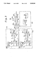
- FIG. 3 shows a circuit diagram of a bias means 1 in FIG. 1,
- FIG. 4 is a circuit diagram of another embodiment according to the present invention.
- FIG. 5 is a circuit diagram of a bias means 1 in FIG. 4,
- FIG. 6 is a circuit diagram of still another embodiment of the delay circuit according to the present invention.
- FIG. 7 is a circuit diagram of still another embodiment of the delay circuit according to the present invention.
- FIG. 8 is a circuit diagram of still another embodiment of the delay circuit according to the present invention.
- FIG. 9 shows operational waveforms of the circuit of FIG. 8,
- FIG. 10 is a circuit diagram of still another embodiment of the delay circuit according to the present invention.
- FIG. 11 shows the operational waveforms of the circuit of FIG. 11,
- FIG. 12 shows a prior delay circuit
- FIG. 13 shows operational waveforms of the circuit of FIG. 12.
- FIG. 1 shows a circuit diagram of the delay circuit according to the present invention.
- the same reference numerals as those in FIG. 12 show the same members.
- the basic idea of the present invention to provide a delay time which is free from temperature change, power supply voltage variation, and process variation is (1) the use of a resistor R c inserted one end of a transistor and power supply (or ground), and to keep constant current in the resistor R c and (2) to compensate for the change of the threshold level of the inverter Q 1 , by adjusting the bias voltage which is applied to the gate of the second transistor M 2 .
- the symbol R shows a ramp generator for providing a ramp voltage starting with a digital input signal V IN
- Q 1 shows an inverter which provides a digital output signal V OUT when said ramp voltage reaches the predetermined threshold voltage of the inverter.
- the ramp generator R has a switching means implemented by a first MOSFET M 1 which is switched ON and OFF by a digital input signal V IN , a charge/discharge circuit having a resistor R c , a second MOSFET M 2 and an operational amplifier A O , and a capacitor C coupled with power supply voltage V DD through said charge/discharge circuit.
- the operational amplifier A O receives the bias voltage V x which compensates temperature variation, power supply variation, and process variation.
- the first MOSFET (metal oxide semiconductor field effect transistor) M 1 is composed of an N-channel element, with a gate G 1 coupled with a digital input signal V IN which is subject to delay, and a source S 1 which is grounded as one port of the power supply.
- the second MOSFET M 2 is composed of a P-channel element with a drain D 2 coupled with a drain D 1 of the first transistor M 1 , and a source S 2 coupled with the power supply voltage V DD through the resistor R c .
- the power supply voltage V DD is DC voltage for operating the delay circuit.
- the operational amplifier A 0 has a positive input (+), a negative input (-), and an output which is coupled with the gate G 2 of the second transistor M 2 .
- the negative input (-) is coupled with the junction of the source S 2 of the second transistor M 2 and the resistor R c .
- the numeral 1 shows a bias means for providing a voltage V x to the operational amplifier A 0 .
- the bias means 1 comprises a first compensation voltage generator 101 which provides the voltage V a which is not affected by temperature change, a second compensation voltage generator 102 which provides the voltage V b which changes linearly according to temperature change, a third compensation voltage generator 103 which provides the threshold voltage V TH of the logic circuit Q 1 , and the voltage combiner 104 which combines the voltages V a , V b , V TH , and the power supply voltage V DD .
- the voltage combiner 104 has an operational amplifier A 11 , and a voltage adder A 12 .
- the operational amplifier A 11 functions as an adder, having a negative input terminal (-) connected to the voltage adder A 12 through the resistor R 11 and the positive input terminal (+) which is coupled with the power supply voltage V DD through the resistor R 12 and grounded through the resistor R 13 .
- the resistor R f1 is connected between the negative input terminal (-) and the output of the amplifier A 11 .
- the output of the amplifier A 11 provides the bias voltage V x which is applied to the positive input of the operational amplifier A 0 .
- the resistance of the resistors R f1 and R 12 is selected to be (K 1 ⁇ R a1 ) where R a1 is resistance of the resistors R 11 and R 13 , and K 1 is constant.
- the voltage adder A 12 provides the combined DC sum V 01 as follows.
- the sum V 01 of the output of the voltage adder A 12 is applied to the negative input (-) of the operational amplifier A 11 through the resistor R 11 .
- the positive input (+) of the operational amplifier A 11 receives the input voltage which divides the power supply voltage V DD by the resistors R 12 and R 13 .
- the output V x of the operational amplifier A 11 is;
- the voltage V x which is the output of the operational amplifier A 11 is applied to the positive input (+) of the operational amplifier A 0 , which functions so that the voltages at two input terminals (-) and (+) are equal to each other. Therefore, the junction (b) of the source S 2 of the second FET M 2 and the resistor R 2 is at the potential equal to V x .
- FIG. 2 shows the operational waveforms of the apparatus of FIG. 1.
- a digital input signal V in (FIG. 2(a)) is at high level, both the FET's M 1 and M 2 are in active state.
- the ratio (W/L) of the gate width W to the channel length L of the first FET M 1 is sufficiently larger than than (W/L) of the second FET M 2 , then, the voltage between the gate and the source of the first FET M 1 is higher than that of the second FET M 2 , the potential at the point (a) which is the junction of the drains D 1 and D 2 of two FET's is at low level (0 volt) as shown in FIG. 2(b).
- the delay time T d is the time between t 0 and t 1 until the inverter Q 1 provides an output signal V OUT , and is expressed as follows.
- T d (V TH ⁇ C)/I DP
- I DP is drain current of the second FET M 2 , and is equal to the charge current of the capacitor C.
- the operational amplifier A 0 functions to adjust the potential at the point (b) which is the junction of the source S 2 of the second FET M 2 and the resistor R c equal to the potential V x , the current I DP is expressed as follows.
- the delay time T d is expressed as follows. ##EQU1##
- V DD -V x In order to prevent the change of T d by the change of the source voltage and temeperature, (V DD -V x ) must be proportional to V TH , and the temperature coefficient of (V DD -V x ) must be equal to the temperature coefficient ⁇ of the resistor R c .
- the bias voltage V x must satisfy the following equation (2).
- (V DD -V x ) which is the denominator of the equation (1) has the positive temperature coefficient K 0 (V/°C.), and has the value K 1 ⁇ V TH which is proportional to the threshold voltage V TH at the reference temperature T 0 .
- the value K 1 is constant.
- the delay time T d is then obtained by the equation (3) by combining the equations (2) and (1).
- the equation (4) shows that the delay time T d is free from temperature variation, power voltage variation, and process variation.
- FIG. 3 shows a circuit diagram of the bias means 1 which provides the bias voltage V x for satisfying above equations (2) through (4).
- the first compensation voltage generator 101 which provides the voltage V a which is free from temperature change has an operational amplifier A 21 , a pair of bipolar transistors Q 11 and Q 21 having the different emitter area from each other in diode connection, the resistors R 31 , R 32 and R 33 , and the other operational amplifier A 22 .
- the operational amplifier A 21 has the positive input connected to the emitter of the bipolar transistor Q 11 , and the negative input (-) connected to the junction of the resistors R 31 and R 32 .
- the operational amplifier A 22 has the negative input (-) connected to the output of the operational amplifier A 21 through the resistor R 41 , and the positive input (+) connected to the power source V DD through the resistor R 42 and the ground through the resistor R 43 .
- the output of the amplifier A 22 is connected to the negative input (-) through the feedback resistor R f3 .
- the resistance of the resistors R 43 and R f3 is selected to be K 2 ⁇ R a2 where R a2 is the resistance of the resistors R 41 and R 42 .
- the second compensation voltage generator 102 for generating the voltage V b which changes linearly according to temperature change has the operational amplifier A 31 , a pair of bipolar transistors Q 31 and Q 41 having the different emitter area from each other in diode connection, the resistors R 51 , R 52 and R 53 , and the operational amplifier A 32 .
- the operational amplifier A 31 has the positive input (+) connected to the emitter of the bipolar transistor Q 31 , and the negative input (-) connected to the junction of the resistors R 51 and R 52 .
- the operational amplifier A 32 has the negative input (-) connected to the output of the amplifier A 31 through the resistor R 61 , and the positive input (+) connected to the power source voltage V DD through the resistor R 62 and the ground through the resistor R 63 .
- the output of the amplifier A 32 is connected to the negative input through the feedback resistor R f4 .
- the third compensation voltage generator 103 for providing the threshold voltage V TH of the inverter Q 1 has a logic circuit Q 51 and an operational amplifier A 41 .
- the logic circuit Q 51 is the same inverter as the inverter Q 1 , mounted on the same semiconductor substrate as that of Q 1 .
- the output of the inverter Q 51 is connected to the input of the same. It should be noted that the output of the all feedback type inverter in which the output is connected to the input, is equal to the threshold voltage of the own inverter. Therefore, the logic circuit Q 51 provides the threshold voltage V TH of the inverter Q 1 .
- the output of the inverter Q 51 is applied to the positive input of the operational amplifier A 41 which composes an impedance converter with the unit gain in the unity feedback connection so that the threshold voltage V TH is output with low impedance.
- the combiner 104 has the operational amplifiers A 11 and A 12 .
- the operational amplifier A 12 has the negative input (-) connected to the output V a of the means 101 which provides the voltage V a free from temperature, and the positive input (+) connected to the output V b which changes linearly according to temperature change through the resistor R 22 and the threshold voltage V TH through the resistor R 23 .
- the output voltage V 1 of the operational amplifier A 21 in the compensation voltage generator 101, and the output voltage V 2 of the operational amplifier A 31 of the second compensation voltage generator 102, are expressed as follows, respectively.
- V BE1 voltage between a base and an emitter of a bipolar transistor Q 11
- V BE3 voltage between a base and an emitter of a bipolar transistor Q 31
- V BE1 and V BE3 have the negative temperature coefficient about -2 mV/°C.
- V p1 (T) and V p2 (T) are proportional to absolute temperature (T).
- the temperature coefficient of V BE1 +V p1 (T) is zero by designing the ratio R 32 /R 33 as follows.
- That voltage is free from the temperature change and the power supply voltage change, and is defined as a constant voltage V REF1 , and then,
- the voltage V 2 includes the power supply voltage V DD , that power supply voltage V DD is subtracted from V 2 by using the operational amplifier A 32 , which provides the output V b ;
- the offset voltage V b (T 0 ) is subtracted from V b in order to provide the compensation voltage with the temperature coefficient K 0 , and the value zero (0) at the reference temperature (T 0 ), as shown in the equation (2). That offset voltage is derived from the reference voltage V REF1 obtained in the first compensation voltage generator 101.
- the operational amplifier A 22 effects the subtraction V DD -V 1 , and provides the factor K 2 .
- the operational amplifier A 12 functions as an adder, providing the output voltage V 01 : ##EQU2##
- the operational amplifier A 12 effects the subtraction V b -V a
- the threshold voltage V TH which is the output of the operational amplifier A 41 is added to the difference V b -V a .
- the operational amplifier A 11 effects the subtraction and the output V x is; ##EQU3##
- the value V x is obtained by applying V DD to the positive input and V 01 to the negative input of the operational amplifier A 11 .
- the factor K 1 is determined by the resistance of the resistors R 11 through R 13 and the feedback resistor R f1 .
- the factor K 1 is less than 1 (K 1 ⁇ 1) so that the ramp voltage has some desired level, considering the dynamic range of the operational amplifier A 0 , and the ratio (W/L) in size of the second FET M 2 , and that the voltage drop in the resistor R c is preferably low.
- npn bipolar transistors Q 11 , Q 21 , Q 31 and Q 41 are produced through P well C-MOS process with an emitter by an n + diffusion layer which is produced through the same steps as those of a source/drain of an N channel MOS FET, a base with a P well, and a collector with an N type substrate.
- FIG. 4 shows a circuit diagram of another embodiment of the present invention.
- the same numerals as those in FIG. 1 show the same members.
- the feature of FIG. 4 as compared with FIG. 1 is that the resistor R c is coupled in the ground side, instead of the power source side.
- the ramp voltage in FIG. 4 is decreasing in voltage as shown in FIG. 13, while the ramp voltage in FIG. 1 is increasing in voltage as shown in FIG. 2(b).
- the first MOSFET M 1 is composed of a P-channel element with a gate G 1 accepting an input digital signal V IN which is subject to be delayed, and a source S 1 connected to the power supply voltage V DD .
- the second MOSFET M 2 is composed of an N-channel element, with a drain D 2 connected to the drain D 1 of the first FET M 1 , the source S 2 grounded through the resistor R c .
- the capacitor C is charged when the digital input signal V IN is in low level and the first FET M 1 is conducted, and said capacitor C is discharged through the second FET M 2 and the resistor R c provides a ramp voltage when the digital input signal V IN is in high level and the first FET M 1 is in cutoff state.
- the voltage across the capacitor C, or the potential at the point (a) is converted to a digital form by a logic circuit Q 1 which has the threshold voltage V TH , and provides the delayed signal.
- the operational waveforms in FIG. 4 are the same as those in FIG. 13.
- the bias means 1 has a first voltage generator 101 which provides a compensation voltage V a free from temperature variation, a second voltage generator 102 which provides a compensation voltage V b which is linear to temperature variation, a third voltage generator 104 which provides the threshold voltage V TH of the inverter Q 1 , and a voltage combiner 104.
- the operational amplifier A 0 has the positive input (+) and the negative input (-) and the output.
- the negative input (-) is connected to the source S 2 of the second FET M 2
- the output is connected to the gate G 2 of the second FET M 2 .
- the voltage combiner 104 provides the DC voltage V x by using the outputs of the means 101, 102, 103, and the power source voltage V DD .
- the voltage combiner 104 has an operational amplifier A 11 and a voltage adder A 12 .
- the operational amplifier A 11 composes an adder with a negative input (-) connected to the threshold voltage V TH through the resistor R 11 , and a positive input (+) connected to the power supply voltage V DD through the resistor R 12 , and grounded through the resistor R 13 .
- the output of the amplifier A 11 is connected to the negative input (-) through the resistor R f1 , and applied to said voltage adder A 12 .
- the resistance of the resistors R f1 and R 13 is designed to be K 1 ⁇ R a1 , where R a1 is the resistance of the resistors R 11 and R 12 , and K 1 is constant.
- the output of the operational amplifier is K 1 (V DD -V TH ).
- the voltage adder A 12 provides the DC voltage V x as follows.
- the DC voltage V x is applied to the positive input (+) of the operational amplifier A 0 , which provies the bias voltage to the second FET M 2 so that the potential at the resistor R c is equal to the DC voltage V x .
- the delay time T d in FIG. 4 is shown below.
- I DN is drain current of the second FET M 2 , and is the discharge current from the capacitor C.
- the delay time T d is; ##EQU4## where ⁇ is temperature coefficient of the resistor R c , and is expressed as follows.
- R 0 is the resistance of the resistor R c at the reference temperature T 0 .
- the conditions to have delay time free from temperature variation are that the voltage V x is proportional to the voltage (V DD -V TH ), and that the temperature coefficient of the voltage V x is equal to the temperature coefficient ⁇ of the resistor R c .
- the voltage V x must be expressed as follows, where K 0 is positive temperature gradient (V/°C.), and K 1 is constant.
- the delay time T d is expressed as follows, and that delay time T d is free from temperature variation, power supply voltage, and producing process.
- FIG. 5 shows a circuit diagram of the bias means 1, which satisfies the above conditions in the equations 8 through 10.
- the voltage generator 101 which provides the voltage V 1 free from the power supply voltage variation has an operational amplifier A 21 , a pair of pnp bipolar transistors Q 11 and Q 21 having different emitter area from each other in diode connection, resistors R 31 , R 32 and R 33 , and another operational amplifier A 22 .
- the operational amplifier A 21 has a positive input (+) connected to an emitter of a bipolar transistor Q 11 , and a negative input (-) connected to a junction of the resistors R 31 and R 32 .
- the operational amplifier A 22 has a negative input (-) connected to output of the operational amplifier A 21 through the resistor R 41 , and the positive input (+) connected to the power supply voltage V DD through the resistor R 43 and is grounded through the resistor R 42 .
- the output of the amplifier A 22 is connected to the negative input (-) through the resistor R f3 .
- the resistance of the resistors R 43 and R f3 is (K 2 ⁇ R a2 ) where R a2 is resistance of the resistors R 41 and R 42 .
- the voltage generator 102 for providing the voltage V 2 which is linear to temperature change has an operational amplifier A 31 , a pair of npn bipolar transistors Q 31 , and Q 41 , the resistors R 51 , R 52 and R 53 , and the other operational amplifier A 32 .
- the operational amplifier A 31 has a positive input (+) connected to an emitter of the bipolar transistor R 53 , and a negative input (-) connected to a junction of the resistors R 51 and R 52 .
- the operational amplifier A 32 has a negative input (-) connected to an output of the operational amplifier A 31 through the resistor R 61 , and a positive input (+) connected to the power supply voltage V DD through the resistor R 63 and is grounded through the resistor R 62 .
- the output of the operational amplifier A 32 is connected to the negative input (-) through the feedback resistor R f4 .
- the resistance of the resistors R 61 through R 63 , and the resistors R f4 is the same as one another, and is expressed as R a3 .
- the voltage generator 103 for taking the threshold voltage V TH of the logic circuit Q 1 has the logic circuit Q 51 , and the operational amplifier A 41 .
- the logic circuit Q 51 is similar to the logic circuit Q 1 in FIG. 4, and the output of Q 51 is connected to the input of the same.
- the output voltage of a full feedback type inverter which connects the output to the input is equal to the threshold voltage of the inverter itself. So, the logic circuit Q 51 provides the voltage which is essentially equal to the threshold voltage V TH of the logic circuit Q 1 .
- the output V TH is applied to the positive input (+) of the operational amplifier A 41 , which constitutes an impedance converter with unit gain by unity feedback connection, and provides the low impedance output voltage V TH .
- the voltage combiner 104 has operational amplifiers A 11 and A 12 .
- the operational amplifier A 11 has a negative input (-) connected to the output of the operational amplifier A 41 , and a positive input (+) connected to the power voltage V DD through the resistor R 12 and is grounded through the resistor R 13
- the resistor R f1 is a feedback resistor.
- the resistance of the resistors R 13 and R f1 is designed to be K 1 ⁇ R a1 , where R a1 is the resistance of the resistors R 11 and R 12 .
- the operational amplifier A 12 has a negative input (-) connected to the output of the operational amplifier A 32 through the resistor R 21 , and a positive input (+) connected to the output of the operational amplifier A 22 through the resistor R 22 , and to the output of the operational amplifier A 11 through the resistor R 23 .
- the resistor R f2 is a feedback resistor.
- the resistance of the resistors R 21 through R 23 , and R f2 is the same as one another, and is R a4 .
- FIGS. 4 and 5 The operation of the embodiment of FIGS. 4 and 5 is similar to that of FIGS. 1 through 3.
- FIGS. 1 through 3 is suitable to an N well C-MOS process
- the embodiment of FIGS. 4 and 5 is suitable to a P well C-MOS process.
- FIG. 6 is still another embodiment of the delay circuit according to the present invention.
- the feature of FIG. 6 is the presence of a current mirror circuit B 1 enclosed by a dotted line.
- the embodiment of FIG. 6 is the combination of the embodiment of FIG. 1 and the current mirror circuit B 1 .
- the embodiment of FIG. 6 is advantageous when there are a plurality of delay circuits each of which must compensate temperature variation, power voltage variation, and/or process variation.
- One example of that plurality of delay circuits is a transversal filter in which a plurality of delay circuits coupled in series to each other are used.
- the embodiment of FIG. 6 has the advantage that the compensation circuit which is shown in left side of the line X--X is used common to all the delay circuits T 1 , T 2 , . . . , where T i is a delay element, including a switching transistor M 1 , a capacitor C and an inverter Q 1 .
- the digital input signals to each delay elements are designated as V IN (1), V IN (2) et al, and the output signals are designated as V OUT (1), V OUT (2) et al.
- the first FET M 1 which receives a digital input signal V IN , and a second FET M 2 which receives a bias voltage V x are composed of N-channel elements.
- the current mirror circuit B 1 has a third MOSFET M 3 and a fourth MOSFET M 4 .
- the third FET M 3 is a P-channel element, having a gate G 3 connected to a drain D 3 , a source S 3 connected to the power supply voltage V DD , and said drain D 3 being connected to a drain D 2 of the second FET M 2 .
- the fourth FET M 4 is a P-channel element having a gate G 4 connected to the gate G 3 of the third FET M 3 so that a current mirror circuit is composed, and a drain D 4 connected to the drain D 1 of the first FET M 1 .
- the operational waveforms in FIG. 6 are the same as those in FIG. 2.
- an input digital signal V IN (1) applied to the gate G 1 of the first FET M 1 is at high level, the first FET M 1 is conductive, and the potential at the point (a) is at low level, since the capacitor C discharges through the first FET M 1 .
- the digital input signal V IN (1) changes to low level, the first FET M 1 is cutoff.
- the fourth FET M 4 which is biased by the third FET M 3 , is in active state.
- the fourth FET M 4 composes a current mirror circuit with the third FET M 3 , the current flows in the fourth FET M 4 proportional to the current in the series circuit of the second FET M 2 , the third FET M 3 and the resistor R c .
- the current in the fourth FET M 4 charges the capacitor C, and provides the ramp voltage.
- the structure and the operation of the bias means 1 in FIG. 6 are the same as those in FIGS. 4 and 5.
- the embodiment of FIG. 6 provides the delay time free from temperature variation, power supply voltage variation and process variation.
- FIG. 7 shows a circuit diagram of still another embodiment of the delay circuit according to the present invention, which is the combination of a current mirror circuit B 2 and the embodiment of FIG. 4.
- the first FET M 1 and the second FET M 2 are composed of P-channel elements.
- the third FET M 3 and the fourth FET M 4 which compose the current mirror circuit B 2 are composed of N-channel elements.
- the operational waveforms in FIG. 7 are the same as those in FIG. 13.
- the digital input signal V IN applied to the gate G 1 of the first FET M 1 is in low level, the first FET M 1 is conductive, and the capacitor C is charged.
- the potential at the point (a) at one end of the capacitor C is at a high level.
- the capacitor C discharges through the fourth FET M 4 and the ramp voltage is obtained across the capacitor C.
- the discharge current in the fourth FET M 4 is proportional to the current in the path of the second FET M 2 , the third FET M 3 and the resistor R c , because of the current mirror connection of the third FET M 3 and the fourth FET M 4 .
- bias circuit 1 in FIG. 7 The structure and the operation of the bias circuit 1 in FIG. 7 are the same as that in FIGS. 1 and 3.
- a single bias circuit 1 can compensate for the fluctuation of delay time of a plurality of delay circuits T i .
- the first FET M 1 , the fourth FET M 4 , the capacitor C and the inverter Q 1 compose a delay element, in which a gate G 1 of a first FET M 1 receives a digital input signal V IN , and a gate G 4 of a fourth FET M 4 receives a bias voltage from G 3 of a third FET M 3 which constitutes a current mirror circuit with a fourth FET M 4 .
- a delay element comprising a first FET M 1 , a fourth FET M 4 , a capacitor C and a logic circuit Q 1 must be mounted in plural, but, a single bias means in left portion from the line X--X in FIGS. 6 and 7 can be common to all the delay elements. Therefore, the area of a semiconductor chip can be reduced as compared with that in which no current mirror circuit is used. And, the power consumption is also reduced by the use of a current mirror circuit.
- FIG. 8 shows a circuit diagram of still another embodiment of the delay circuit according to the present invention
- FIG. 9 shows the operational waveforms of the circuit of FIG. 8.
- a digital input signal V IN is separated to two input signals by using a pair of inverters INV 1 and INV 2 so that the polarity of two signals is opposite of each other.
- the first delay circuit or ramp generator R 1 operates to delay the beginning edge of an input pulse
- the second delay circuit R 2 operates to delay the rear edge of an input pulse.
- the logic circuit Q 1 which includes a flip-flop FF combines the outputs of the first delay circuit R 1 and the second delay circuit R 2 .
- the output V OUT of the logic circuit Q 1 has the pulse width equal to that of a digital input pulse V IN , alternatively, the pulse width of the output pulse V OUT may be designed arbitrarily.
- each delay circuits R 1 and R 2 is essentially the same as that in FIG. 1.
- the first delay circuit R 1 comprises a first MOSFET M 11 , a second MOSFET M 21 , a resistor R 10 , an operational amplifier A 10 , and a capacitor C 1 .
- the gate G 21 of the first FET M 11 accepts the digital input signal V IN in the polarity inverted form by the inverter INV 1 .
- the second delay circuit R 2 comprises a first MOSFET M 12 , a second MOSFET M 22 , a resistor R 20 , an operational amplifier A 20 , and a capacitor C 2 .
- the gate G 12 of the first FET M 12 accepts the digital input signal V IN through a pair of series connected inverters INV 1 and INV 2 .
- the polarity of the input of the first FET M 12 is the same as that of the original signal V IN , because of two inverters.
- the logic circuit Q 1 comprises a flip-flop FF and an inverter INV 3 .
- the flip-flop FF has two NOR (not-OR) gates NOR 1 and NOR 2 , which constitute a RS (set-reset) type flip-flop, which is set by the high level output signal of the first delay circuit R 1 , and is reset by the high level output signal of the second delay circuit R 2 .
- each operational amplifiers A 10 and A 20 are connected to the sources S 21 , and S 22 , respectively, which are connected to the power source voltage V DD through the resistors R 10 and R 20 , respectively.
- the outputs of the operational amplifiers are applied to the gates G 21 and G 22 of the second FET's M 21 , and M 22 , respectively.
- the positive inputs (+) of the operational amplifiers A 10 and A 20 are commonly coupled with the output V x of the bias means 1.
- the structure of the bias means 1 is substantially the same as that of FIG. 3, except that the inverter Q 51 in FIG. 3 is replaced to a NOR gate which has the same threshold voltage as that of NOR 1 and NOR 2 .
- the potential at the point (e) which is the output of the inverter INV 2 changes also to low level, where the difference t 2 -t 0 is equal to the pulse width of the digital input pulse.
- the potential at the point (e) is applied to the gate G 12 of the FET M 12 of the second delay circuit D 2 , then, the potential at the point (f) at one end of the capacitor C 2 provides the ramp voltage which begins to increase at time t 2 as shown in FIG. 9(e).
- the ramp voltage reaches the threshold voltage V TH of the flip-flop FF at time t 3 , and then, that flip-flop changes to reset state.
- the output of the inverter INV 3 changes to low level as shown in FIG. 9(f).
- the duration between t 3 and t 2 is the delay time of the rear edge of the digital input pulse.
- the first delay time T dLH and the second delay time T dHL are adjusted by the resistance of the resistors R 10 and R 20 , and the capacitance of the capacitors C 1 and C 2 .
- T dLH is equal to T dHL
- the pulse width of the delayed output pulse V OUT is the same as the pulse width of the input pulse V IN .
- T dLH differs from T dHL
- the pulse width of the output pulse V OUT may be designed arbitrarily.
- FIGS. 8 and 9 can provide a delay time which is free from temperature variation, power supply voltage variation, and/or process variation. And, further, the pulse width of the delayed output pulse may be designed arbitrarily.
- FIG. 6 may be combined to the embodiment of FIGS. 8 and 9.
- the bias circuit 1 in FIG. 6 may be common to the first delay circuit D 1 and the second delay circuit D 2 .
- FIG. 10 shows a circuit diagram of still another embodiment of the delay circuit according to the present invention
- FIG. 11 shows the operational waveforms of FIG. 10.
- the digital input signal V IN in FIG. 10 is separated to two paths by using an inverter INV 1 .
- the first delay circuit R 1 functions to delay the beginning edge of an input pulse
- the second delay circuit R 2 functions to delay the rear edge of an input pulse.
- the logic circuit Q 1 combines the outputs of the first delay circuit R 1 and the second delay circuit R 2 , so that the pulse width of the delay output pulse V OUT may be the same as that of the input pulse V IN , or may be designed arbitrarily.
- the structure of the first delay circuit R 1 and the second delay circuit R 2 is essentially the same as that of FIG. 4.
- the flip-flop FF in the logic circuit Q 1 is composed of NAND gates.
- the first delay circuit R 1 has an operational amplifier A 10 , the resistor R 10 , the first MOSFET M 11 , the second MOSFET M 21 , and the capacitor C 1 .
- the gate G 11 of the first FET M 11 receives the digital input signal V IN .
- the second delay circuit C 2 has an operational amplifier A 20 , a resistor R 20 , a first MOSFET M 12 , a second MOSFET M 22 , and a capacitor C 2 .
- the gate G 12 of the first FET M 12 receives the digital input signal V IN in the reversed polarity inverted by the inverter INV 1 .
- the logic circuit Q 1 has a flip-flop FF which is a RS (set-reset) flip-flop having a pair of NAND gates NAND 1 and NAND 2 , and is set to one state by low level output signal of the first delay circuit R 1 , and is reset to zero state by the low level output signal of the second delay circuit R 2 .
- the output of the NAND 2 is coupled with the output terminal V OUT through the inverter INV 3 .
- the negative inputs (-) of the operational amplifiers A 10 and A 20 are connected to the source S 21 and the source S 22 of the second FET M 21 and M 22 , respectively, and are grounded through the resistors R 10 , and F 20 , respectively.
- the outputs of those amplifiers are connected to the gates G 21 and G 22 of the second FET M 21 and M 22 , respectively.
- the positivie inputs (+) of the operational amplifiers A 10 and A 20 are commonly connected to the output of the bias means 1.
- the pulse width of the input signal V IN is equal to the pulse width of the output pulse V OUT .
- the pulse width of an output pulse may be designed arbitrarily by designing the delay times T dLH and T dHL independently.
- the bias circuit having an operational amplifier A 0 , a resistor R c , and a pair of operational amplifiers M 2 and M 3 in FIG. 7 may be common to both the first delay circuit R 1 and the second delay circuit R 2 .
- a delay line having a plurality of taps may be constituted by a plurality of delay circuits of FIG. 8 or FIG. 10. That delay line is used in a transversal filter.
- the inverter INV 1 is omitted by taking a first input to the gate G 11 at the input of the inverter INV 3 , and a second input to the gate G 12 at the output of the inverter INV 3 .
- the omission of an input inverter INV 1 is advantageous to reduce the load of the output inverter INV 3 which would provide an additional delay time in case of heavy load.
Abstract
A delay circuit for delaying a digital input signal has a ramp generator, a logic circuit which provides a delayed output when the ramp voltage reaches threshold voltage, and a bias circuit which provides bias voltage to the ramp generator so that the delayed output is free from temperature variation, power supply voltage variation and process variation of semiconductor elements.
Description
The present invention relates to a delay circuit for a digital signal suitable for an integrated circuit, in particular, relates to such a delay circuit which is free from temperature variation, power supply voltage variation and/or variation of the production process. The delay time in the present delay circuit is obtained by charging and/or discharging a capacitor through a current source which uses a MOS field effect transistor (FET) to generate a ramp voltage, and determining the delay time by the time until said ramp voltage reaches a threshold level of a logic circuit.
A delay circuit for delaying a digital signal by a predetermined time is essential in a digital circuit field including a personal computer, and/or a digital measurement apparatus, for adjusting the timing of control signals.
Conventionally, a delay circuit has been implemented by using a hybrid IC circuit having an LC delay element and a logic gate for input/output buffer. However, a delay circuit in the form of a monolithic IC has been desired for producing a miniaturized and/or low cost device.
A delay circuit which is suitable for a monolithic integrated circuit has been known by charging or discharging a capacitor through a current source with a MOS field effect transistor to generate a ramp voltage, and the delay time is defined by the time until the ramp voltage reaches a threshold level of a logic circuit.
FIG. 12 shows a circuit diagram of a prior delay circuit which uses a ramp voltage. In the figure, the symbol M1 is a first MOS field effect transistor, M2 is a second MOS field effect transistor, C is a capacitor, Q1 is a logic circuit, VBIAS is DC bias potential, VDD is DC power supply voltage, VIN is an input terminal of a digital signal which is subject to delay, and VOUT is an output terminal of a delayed signal.
In the above embodiment, the first MOS field effect transistor M1 which is a P channel element, has a gate G1 which is coupled with an input terminal VIN, and, a source S1 which is coupled with power supply voltage VDD. The second MOS field effect transistor M2 which is N channel element has a drain D2 which is connected to the drain D1 of the first transistor M1, and the source S2 which is grounded. The gate G2 of the second transistor M2 receives the DC (direct current) bias voltage VBIAS. The capacitor C is coupled between the point (a) which is junction point of the drains D1 and D2 of two transistors, and the ground. The logic circuit Q1 is coupled with the point (a), and provides a logic output signal depending upon the charge in the capacitor C to provide the delayed output signal VOUT. The logic circuit Q1 in the embodiment is implemented by an inverter, which provides low level output when the potential of the point (a) is higher than the threshold level of the inverter, and provides high level output when the potential of the point (a) is lower than said threshold level.
FIG. 13 shows the operational waveforms of the circuit. When an input digital signal VIN is in low level, both the transistors M1 and M2 are active, and the potential on the point (a) is determined by the divisional ratio of the power potential VDD by two transistors M1 and M2. When the ratio (W/L) of the gate width W to the channel length L of the first transistor M1 is considerably large as compared with that of the second transistor M2, the potential at the point (a) is at high level as shown in FIG. 13(b), and the potential is approximately VDD. The voltage between the gate and the source of, the first transistor M1 is larger than that of the second transistor M2.
When the digital input signal VIN changes to high level at time t0 as shown in FIG. 13(a), the first transistor M1 becomes to cutoff state, and therefore, the charge on the capacitor C begins to discharge through the second transistor M2. The gate G2 of the second transistor M2 receives the DC bias voltage VBIAS, and it functions as a constant current source in the saturation region where the following equation is satisifed.
V.sub.DS ≦V.sub.GSN -V.sub.TN
where VDS is the voltage between the drain and the source, VGSN is equal to VBIAS, and VTN is the threshold voltage.
Accordingly, when the digital input signal VIN changes to high level, the potential at the point (a) decreases with approximate linearly as shown in FIG. 13(b).
The potential on the point (a) is monitored by a logic circuit Q1 which is implemented by an inverter, which changes the output signal VOUT from low level to high level as shown in FIG. 13(c), when the input voltage reaches the threshold voltage VTH at time t1.
The delay time Td is the duration between the rising edge of the digital input signal VIN and the rising edge of the output signal of the inverter Q1.
The delay time Td is shown by the following equation.
T.sub.d =(V.sub.DD -V.sub.TH)·C/I.sub.DN
where TTH which is the threshold voltage of the logic circuit Q1, and is expressed as follows provided that the logic circuit Q1 is implemented by a CMOS inverter.
V.sub.TH =(βV.sub.DD +βV.sub.TP +V.sub.TN)/(1+β)
β=[(L.sub.n ·W.sub.p ·μ.sub.p)/L.sub.p ·W.sub.n ·μ.sub.n)].sup.1/2
where VTN (positive), Ln, and Wn are the threshold voltage, channel length, and the gate width, respectively, of the N-channel element which constitutes a CMOS inverter, μn is a mobility of an electron which is a carrier in an N-channel element, VTP (negative), Lp, and Wp are the threshold voltage, the channel length, and the gate width, respectively, of the P-channel element which constitutes a CMOS inverter, and μp is the mobility of a positive hole which is the carrier in a P-channel element.
It should be noted in the above equations that the threshold voltage VTH depends upon the source voltage VDD. For instance, when β=1, VTN =|VTP |, then TTH =0.5VDD.
Further, IDN in said equation for providing the delay time Td is the drain current of the second transistor M2, and is approximately obtained by the following equation.
I.sub.DN =(W.sub.N /L.sub.N)(μ.sub.N C.sub.0 /2)(V.sub.GSN -V.sub.TN).sup.2
where VTN, LN and WN are the threshold voltage, the channel length and the gate width, respectively, of the second transistor M2, μN is the mobility of an electron which is the carrier of the second transistor M2, C0 is the gate capacity for unit area of the second transistor M2.
However, a prior delay circuit as described in FIGS. 12 and 13 has the following disadvantages.
a) As apparent in said equation of IDN, when the carrier mobility μN changes, the drain current IDN changes, and then, the delay time Td changes. The carrier mobility μN becomes small when the temperature becomes high. Therefore, the delay time Td becomes longer depending upon the temperature rise.
b) As apparent from the equation for the threshold voltage VTH, the threshold voltage VTH changes depending upon the channel length Lp or Ln, the gate width Wp or Wn, the mobility μn or μp, and the threshold voltage VTn or VTp, because of the change of the manufacturing process condition.
Further, as apparent from the equation of IDN, the drain current IDN of the second transistor M2 changes, depending upon the channel length LN, the gate width WN, the gate capacity C0, and the threshold voltage VTN because of the manufacturing process change. Thus, the delay time depends upon the error in the production process of transistors.
c) As apparent from the equation of Td, the delay time Td is proportional to (VDD -VTH) which is the difference between the power voltage VDD and the threshold voltage VTH of an inverter, the delay time depends upon the power supply voltage VDD.
It is an object of the present invention to overcome the disadvantages and limitations of a prior delay circuit by providing a new and improved delay circuit.
It is also an object of the present invention to provide a delay circuit which is suitable for implementing an integrated circuit IC.
It is also an object of the present invention to provide a delay circuit in which a delay time is free from errors in the production process, temperature change, and power supply voltage change.
The above and other objects are attained by a delay circuit comprising of at least one ramp generator for providing a ramp voltage starting at digital input signal, a logic circuit accepting said ramp voltage and providing digital output signal which is delayed by a predetermined duration from said digital input signal when said ramp voltage reaches a predetermined threshold voltage, and a bias means for providing bias voltage to said ramp generator; said ramp generator comprising, a switching means comprising a first MOSFET which is switched ON and OFF by said digital input signal, a charge/discharge means comprising a second MOSFET, a resistor which is connected in series to a drain-source circuit of said second MOSFET, and an operational amplifier with an output coupled with a gate of said second MOSFET, a negative input coupled with junction of said resistor and said second MOSFET, and a positive input which accepts a bias voltage, and a capacitor which is charged and/or discharged through said charge/discharge circuit, and provides said ramp voltage across the capacitor; said bias means comprising at least one of means for providing voltage proportional to temperature variation and means for providing voltage proportional to said threshold voltage of said logic circuit.
In one modification, a current mirror circuit is coupled with said charge/discharge means so that a single bias means is enough for a plurality of delay circuits which are subject to compensate temperation change, power supply change, and/or production error.
Still preferably, a pair of delay circuits which receives a common digital input signal in opposite polarity are used to provide a delayed output signal in which both beginning edge and rear edge of an input pulse are delayed.
The foregoing and other objects, features, and attendant advantages of the present invention will be appreciated as the same become better understood by means of the following description and accompanying drawings wherein;
FIG. 1 is a circuit diagram of the delay circuit of the first embodiment according to the present invention,
FIG. 2 shows operational waveforms in the circuit of FIG. 1,
FIG. 3 shows a circuit diagram of a bias means 1 in FIG. 1,
FIG. 4 is a circuit diagram of another embodiment according to the present invention,
FIG. 5 is a circuit diagram of a bias means 1 in FIG. 4,
FIG. 6 is a circuit diagram of still another embodiment of the delay circuit according to the present invention,
FIG. 7 is a circuit diagram of still another embodiment of the delay circuit according to the present invention,
FIG. 8 is a circuit diagram of still another embodiment of the delay circuit according to the present invention,
FIG. 9 shows operational waveforms of the circuit of FIG. 8,
FIG. 10 is a circuit diagram of still another embodiment of the delay circuit according to the present invention,
FIG. 11 shows the operational waveforms of the circuit of FIG. 11,
FIG. 12 shows a prior delay circuit, and
FIG. 13 shows operational waveforms of the circuit of FIG. 12.
FIG. 1 shows a circuit diagram of the delay circuit according to the present invention. The same reference numerals as those in FIG. 12 show the same members.
The basic idea of the present invention to provide a delay time which is free from temperature change, power supply voltage variation, and process variation is (1) the use of a resistor Rc inserted one end of a transistor and power supply (or ground), and to keep constant current in the resistor Rc and (2) to compensate for the change of the threshold level of the inverter Q1, by adjusting the bias voltage which is applied to the gate of the second transistor M2.
In FIG. 1, the symbol R shows a ramp generator for providing a ramp voltage starting with a digital input signal VIN, and Q1 shows an inverter which provides a digital output signal VOUT when said ramp voltage reaches the predetermined threshold voltage of the inverter. The ramp generator R has a switching means implemented by a first MOSFET M1 which is switched ON and OFF by a digital input signal VIN, a charge/discharge circuit having a resistor Rc, a second MOSFET M2 and an operational amplifier AO, and a capacitor C coupled with power supply voltage VDD through said charge/discharge circuit. The operational amplifier AO receives the bias voltage Vx which compensates temperature variation, power supply variation, and process variation.
The first MOSFET (metal oxide semiconductor field effect transistor) M1 is composed of an N-channel element, with a gate G1 coupled with a digital input signal VIN which is subject to delay, and a source S1 which is grounded as one port of the power supply.
The second MOSFET M2 is composed of a P-channel element with a drain D2 coupled with a drain D1 of the first transistor M1, and a source S2 coupled with the power supply voltage VDD through the resistor Rc. The power supply voltage VDD is DC voltage for operating the delay circuit.
The operational amplifier A0 has a positive input (+), a negative input (-), and an output which is coupled with the gate G2 of the second transistor M2. The negative input (-) is coupled with the junction of the source S2 of the second transistor M2 and the resistor Rc.
The numeral 1 shows a bias means for providing a voltage Vx to the operational amplifier A0. The bias means 1 comprises a first compensation voltage generator 101 which provides the voltage Va which is not affected by temperature change, a second compensation voltage generator 102 which provides the voltage Vb which changes linearly according to temperature change, a third compensation voltage generator 103 which provides the threshold voltage VTH of the logic circuit Q1, and the voltage combiner 104 which combines the voltages Va, Vb, VTH, and the power supply voltage VDD. The voltage combiner 104 has an operational amplifier A11, and a voltage adder A12.
The operational amplifier A11 functions as an adder, having a negative input terminal (-) connected to the voltage adder A12 through the resistor R11 and the positive input terminal (+) which is coupled with the power supply voltage VDD through the resistor R12 and grounded through the resistor R13. The resistor Rf1 is connected between the negative input terminal (-) and the output of the amplifier A11. The output of the amplifier A11 provides the bias voltage Vx which is applied to the positive input of the operational amplifier A0. The resistance of the resistors Rf1 and R12 is selected to be (K1 ·Ra1) where Ra1 is resistance of the resistors R11 and R13, and K1 is constant.
The voltage adder A12 provides the combined DC sum V01 as follows.
V.sub.01 =V.sub.TH +V.sub.b -V.sub.a
The sum V01 of the output of the voltage adder A12 is applied to the negative input (-) of the operational amplifier A11 through the resistor R11. The positive input (+) of the operational amplifier A11 receives the input voltage which divides the power supply voltage VDD by the resistors R12 and R13. Thus, the output Vx of the operational amplifier A11 is;
V.sub.x =V.sub.DD -K.sub.1 V.sub.01
The voltage Vx which is the output of the operational amplifier A11 is applied to the positive input (+) of the operational amplifier A0, which functions so that the voltages at two input terminals (-) and (+) are equal to each other. Therefore, the junction (b) of the source S2 of the second FET M2 and the resistor R2 is at the potential equal to Vx.
FIG. 2 shows the operational waveforms of the apparatus of FIG. 1. When a digital input signal Vin (FIG. 2(a)) is at high level, both the FET's M1 and M2 are in active state. Provided that the ratio (W/L) of the gate width W to the channel length L of the first FET M1 is sufficiently larger than than (W/L) of the second FET M2, then, the voltage between the gate and the source of the first FET M1 is higher than that of the second FET M2, the potential at the point (a) which is the junction of the drains D1 and D2 of two FET's is at low level (0 volt) as shown in FIG. 2(b).
When the digital input signal VIN turns to low level at the time t0 as shown in FIG. 2(a), the first FET M1 goes to a cutoff state, and the capacitor C is charged through the resistor Rc and the second FET M2. Therefore, the potential at the point (a) at one end of the capacitor C increases as shown in FIG. 2(b). The potential at the point (a) is applied to the inverter Q1, which turns an output signal from high level to low level at the time t1 when the potential at the point (a) reaches the threshold level VTH of the inverter Q1 as shown in FIG. 2(c).
The delay time Td is the time between t0 and t1 until the inverter Q1 provides an output signal VOUT, and is expressed as follows.
Td =(VTH ·C)/IDP
where IDP is drain current of the second FET M2, and is equal to the charge current of the capacitor C.
Since the operational amplifier A0 functions to adjust the potential at the point (b) which is the junction of the source S2 of the second FET M2 and the resistor Rc equal to the potential Vx, the current IDP is expressed as follows.
I.sub.DP =(V.sub.DD -V.sub.x)/R.sub.c
It should be noted in the above equation that the use of the operational amplifier A0 which provides the potential Vx at one end of the resistor Rc removes the delay time error because of the process error of a semiconductor, since the current IDP is determined only by VDD and Rc, but is free from mobility, and/or gate capacitance of semiconductor elements.
The delay time Td is expressed as follows. ##EQU1##
In order to prevent the change of Td by the change of the source voltage and temeperature, (VDD -Vx) must be proportional to VTH, and the temperature coefficient of (VDD -Vx) must be equal to the temperature coefficient α of the resistor Rc.
In other words, the bias voltage Vx must satisfy the following equation (2).
(V.sub.DD -V.sub.x)=K.sub.1 [V.sub.TH +K.sub.0 (T-T.sub.0) (2)
In the equation (2), (VDD -Vx) which is the denominator of the equation (1) has the positive temperature coefficient K0 (V/°C.), and has the value K1 ·VTH which is proportional to the threshold voltage VTH at the reference temperature T0. The value K1 is constant.
The delay time Td is then obtained by the equation (3) by combining the equations (2) and (1).
T.sub.d =C·R.sub.0 [1+α(T-T.sub.0)]V.sub.TH /[K.sub.1 (V.sub.TH +K.sub.0 (T-T.sub.0))]=C·R.sub.0 [1+α(T-T.sub.0)]V.sub.TH /[K.sub.1 V.sub.TH (1+β(T-T.sub.0)))](3)
where β=K0 /VTH.
Provided that K0 =α·VTH, and α=β are satisfied, the delay time Td is;
T.sub.d =C·R.sub.0 /K.sub.1 (4)
The equation (4) shows that the delay time Td is free from temperature variation, power voltage variation, and process variation.
FIG. 3 shows a circuit diagram of the bias means 1 which provides the bias voltage Vx for satisfying above equations (2) through (4). The first compensation voltage generator 101 which provides the voltage Va which is free from temperature change has an operational amplifier A21, a pair of bipolar transistors Q11 and Q21 having the different emitter area from each other in diode connection, the resistors R31, R32 and R33, and the other operational amplifier A22. The operational amplifier A21 has the positive input connected to the emitter of the bipolar transistor Q11, and the negative input (-) connected to the junction of the resistors R31 and R32.
The operational amplifier A22 has the negative input (-) connected to the output of the operational amplifier A21 through the resistor R41, and the positive input (+) connected to the power source VDD through the resistor R42 and the ground through the resistor R43. The output of the amplifier A22 is connected to the negative input (-) through the feedback resistor Rf3. The resistance of the resistors R43 and Rf3 is selected to be K2 ·Ra2 where Ra2 is the resistance of the resistors R41 and R42.
The second compensation voltage generator 102 for generating the voltage Vb which changes linearly according to temperature change has the operational amplifier A31, a pair of bipolar transistors Q31 and Q41 having the different emitter area from each other in diode connection, the resistors R51, R52 and R53, and the operational amplifier A32. The operational amplifier A31 has the positive input (+) connected to the emitter of the bipolar transistor Q31, and the negative input (-) connected to the junction of the resistors R51 and R52. The operational amplifier A32 has the negative input (-) connected to the output of the amplifier A31 through the resistor R61, and the positive input (+) connected to the power source voltage VDD through the resistor R62 and the ground through the resistor R63. The output of the amplifier A32 is connected to the negative input through the feedback resistor Rf4. The resistance of the resistors R61 through R63, and the feedback resistor Ff4 is essentially the same as one another (=Ra3).
The third compensation voltage generator 103 for providing the threshold voltage VTH of the inverter Q1 has a logic circuit Q51 and an operational amplifier A41. The logic circuit Q51 is the same inverter as the inverter Q1, mounted on the same semiconductor substrate as that of Q1. The output of the inverter Q51 is connected to the input of the same. It should be noted that the output of the all feedback type inverter in which the output is connected to the input, is equal to the threshold voltage of the own inverter. Therefore, the logic circuit Q51 provides the threshold voltage VTH of the inverter Q1. The output of the inverter Q51 is applied to the positive input of the operational amplifier A41 which composes an impedance converter with the unit gain in the unity feedback connection so that the threshold voltage VTH is output with low impedance.
The combiner 104 has the operational amplifiers A11 and A12. The operational amplifier A12 has the negative input (-) connected to the output Va of the means 101 which provides the voltage Va free from temperature, and the positive input (+) connected to the output Vb which changes linearly according to temperature change through the resistor R22 and the threshold voltage VTH through the resistor R23. The resistor Rf2 is a feedback resistor. The resistance of the resistors R21 through R23 and Ff2 is essentially the same as one another (=Ra4).
In the above structure, the output voltage V1 of the operational amplifier A21 in the compensation voltage generator 101, and the output voltage V2 of the operational amplifier A31 of the second compensation voltage generator 102, are expressed as follows, respectively.
V.sub.1 =V.sub.DD -[V.sub.BE1 +V.sub.p1 (T)] (5)
V.sub.2 =V.sub.DD -[V.sub.BE3 +V.sub.p2 (T)] (6)
where;
Vp1 (T)=(kT/q)(R32 /R31)ln[(I1 /I2)(S2 /S1)]=(kT/q)(R32 /R31)ln[(R32 /R31)(S2 /S1)]
Vp2 (T)=(kT/q)(R52 /R51)ln[I3 /I4)(S4 /S3)]=(kT/q)(R52 /R51)ln[R52 /R53)(S4 /S3)]
k; Boltzmann's constant
T; absolute temperature
q; charge of an electron
S1 ; area of an emitter of a bipolar transistor Q11
S2 ; area of an emitter of a bipolar transistor Q21
S3 ; area of an emitter of a bipolar transistor Q31
S4 ; area of an emitter of a bipolar transistor Q41
VBE1 ; voltage between a base and an emitter of a bipolar transistor Q11
VBE3 ; voltage between a base and an emitter of a bipolar transistor Q31
It should be appreciated that voltages VBE1 and VBE3 have the negative temperature coefficient about -2 mV/°C., and Vp1 (T) and Vp2 (T) are proportional to absolute temperature (T).
According to the present invention, the voltage V1 is determined so that the temperature coefficient in the equation (5) is zero, and V2 is determined so that the temperature coefficient in the equation (6) is constant (K0 =αVTH mV/°C.).
The conditions that the temperature coefficient of V1 is zero are as follows n the equation (5).
(αV.sub.BE1 /αT)+(αV.sub.p1 (T)/αT)=0, and
(αV.sub.BE1 /αT)+(k/q)(R.sub.32 /R.sub.31)ln[(R.sub.32 R.sub.33)(S.sub.2 /S.sub.1)]=0
Assuming that;
(αV.sub.BE1 /αT)=-2 [mV/°C.], R.sub.32 =R.sub.33, and S.sub.2 /S.sub.1 =10
then, the temperature coefficient of VBE1 +Vp1 (T) is zero by designing the ratio R32 /R33 as follows.
R.sub.32 /R.sub.31 =-(αV.sub.BE1 /αT)/[(k/q)ln[(R.sub.32 /R.sub.33)(S.sub.2 /S.sub.1)]]=2.0/[(0.085)ln(10)]=10
Assuming that the reference temperature T0 is 300° K. (absolute temperature), and VBE1 at that reference temperature is 0.7 V, then, the following equation is satisfied.
V.sub.BE1 (T.sub.0)+V.sub.p1 (T.sub.0)=0.7+(0.085.10.sup.-3)(300)(10)ln(10)=1.3 [V]
That voltage is free from the temperature change and the power supply voltage change, and is defined as a constant voltage VREF1, and then,
V.sub.1 =V.sub.DD -V.sub.REF1
On the other hand, the conditions that V2 has the temperature coefficient K0 (mV/°C.) in the equation (6) are as follows.
(αV.sub.BE3 /αT)+(αV.sub.p2 (T)/αT)=K.sub.0, and
(αV.sub.BE3 /αT)+(k/q(R.sub.52 /R.sub.51)ln[(R.sub.52 /R.sub.53)(S.sub.4 /S.sub.3)]=k.sub.0
where K0 =αVTH.
Assuming in a numerical embodiment that α=800 [ppm/°C., and VTH =2.5 V, then,
K.sub.0 =αV.sub.TH =2.0 [mV/°C.]
Assuming that (αBBE3 /αT)=-2 (mV/°C.), and R52 =R53, and S4 /S3 =20, the ratio of R52 /R51 for satisfying above conditions is;
R.sub.52 /R.sub.51 =[K.sub.0 -αV.sub.BE3 /αT)/((k/q)ln((R.sub.52 /R.sub.53)(S.sub.4 /S.sub.3))]=(2.0-(-2.0))/(0.085)ln(20)=16
Therefore, when R52 =R53, S4 /S3 =20, and R52 /R51 =16, the temperature coefficient of VBE3 +Vp2 (T) is;
αV.sub.TH =+2.0 [mV/°C.]
Since the voltage V2 includes the power supply voltage VDD, that power supply voltage VDD is subtracted from V2 by using the operational amplifier A32, which provides the output Vb ;
V.sub.b =V.sub.DD -V.sub.2 =V.sub.BE3 +V.sub.p2 (T)
That voltage Vb =VBE3 +Vp2 (T) has the temperature coefficient αVTH =+2.0 mV/°C.
Next, the offset voltage Vb (T0) is subtracted from Vb in order to provide the compensation voltage with the temperature coefficient K0, and the value zero (0) at the reference temperature (T0), as shown in the equation (2). That offset voltage is derived from the reference voltage VREF1 obtained in the first compensation voltage generator 101.
As the voltage V1 in the first compensation voltage generator 101 includes the power supply voltage VDD, the operational amplifier A22 effects the subtraction VDD -V1, and provides the factor K2.
V.sub.a =K.sub.2 (V.sub.DD -V.sub.1)=K.sub.2 ·V.sub.REF1
The factor K2 must satisfy the following condition so that Vb (T0)=VBE3 (T0)+Vp2 (T0) is satisfied (the value Vb is zero at reference temperature T0).
K.sub.2 ·V.sub.REF1 =V.sub.BE3 (T.sub.0)+V.sub.p2 (T.sub.0)=V.sub.BE3 (T.sub.0)+(k/q)(R.sub.52 /R.sub.51)(T.sub.0)ln[(R.sub.52 /R.sub.53)(S.sub.4 /S.sub.3)]
Assuming that VBE3 (T0)=0.7 V, R52 =R53, S4 /S3 =20, R52 /R51 =16, and VREF1 =1.3 V, then, the value K2 is obtained as follows.
K.sub.2 ·V.sub.REF1 =V.sub.BE3 (T.sub.0)+(k/q)(R.sub.52 /R.sub.51)(T.sub.0)ln[(R.sub.52 /R.sub.53)(S.sub.4 /S.sub.3)]=1.9
K.sub.2 =1.9/V.sub.REF1 =1.9/1.3=1.5
The operational amplifier A12 functions as an adder, providing the output voltage V01 : ##EQU2## Thus, the operational amplifier A12 effects the subtraction Vb -Va, and the threshold voltage VTH which is the output of the operational amplifier A41 is added to the difference Vb -Va.
The operational amplifier A11 effects the subtraction and the output Vx is; ##EQU3## The value Vx is obtained by applying VDD to the positive input and V01 to the negative input of the operational amplifier A11. The factor K1 is determined by the resistance of the resistors R11 through R13 and the feedback resistor Rf1.
It is preferable that the factor K1 is less than 1 (K1 <1) so that the ramp voltage has some desired level, considering the dynamic range of the operational amplifier A0, and the ratio (W/L) in size of the second FET M2, and that the voltage drop in the resistor Rc is preferably low.
The npn bipolar transistors Q11, Q21, Q31 and Q41 are produced through P well C-MOS process with an emitter by an n+ diffusion layer which is produced through the same steps as those of a source/drain of an N channel MOS FET, a base with a P well, and a collector with an N type substrate.
It should be noted in FIGS. 1 through 3 that the use of only compensation means 101 and 102 is useful for compensating only temperature change. Similarly, the use of only the compensation means 103 is useful for compensating the change of the threshold voltage. Of course, when those three means 101, 102 and 103 are used, both the temperature change and threshold voltage change are compensated for.
FIG. 4 shows a circuit diagram of another embodiment of the present invention. In FIG. 4, the same numerals as those in FIG. 1 show the same members. The feature of FIG. 4 as compared with FIG. 1 is that the resistor Rc is coupled in the ground side, instead of the power source side.
The ramp voltage in FIG. 4 is decreasing in voltage as shown in FIG. 13, while the ramp voltage in FIG. 1 is increasing in voltage as shown in FIG. 2(b).
The first MOSFET M1 is composed of a P-channel element with a gate G1 accepting an input digital signal VIN which is subject to be delayed, and a source S1 connected to the power supply voltage VDD.
The second MOSFET M2 is composed of an N-channel element, with a drain D2 connected to the drain D1 of the first FET M1, the source S2 grounded through the resistor Rc.
In this embodiment, the capacitor C is charged when the digital input signal VIN is in low level and the first FET M1 is conducted, and said capacitor C is discharged through the second FET M2 and the resistor Rc provides a ramp voltage when the digital input signal VIN is in high level and the first FET M1 is in cutoff state. The voltage across the capacitor C, or the potential at the point (a) is converted to a digital form by a logic circuit Q1 which has the threshold voltage VTH, and provides the delayed signal. The operational waveforms in FIG. 4 are the same as those in FIG. 13.
The bias means 1 has a first voltage generator 101 which provides a compensation voltage Va free from temperature variation, a second voltage generator 102 which provides a compensation voltage Vb which is linear to temperature variation, a third voltage generator 104 which provides the threshold voltage VTH of the inverter Q1, and a voltage combiner 104.
The operational amplifier A0 has the positive input (+) and the negative input (-) and the output. The negative input (-) is connected to the source S2 of the second FET M2, the output is connected to the gate G2 of the second FET M2.
The voltage combiner 104 provides the DC voltage Vx by using the outputs of the means 101, 102, 103, and the power source voltage VDD.
The voltage combiner 104 has an operational amplifier A11 and a voltage adder A12. The operational amplifier A11 composes an adder with a negative input (-) connected to the threshold voltage VTH through the resistor R11, and a positive input (+) connected to the power supply voltage VDD through the resistor R12, and grounded through the resistor R13. The output of the amplifier A11 is connected to the negative input (-) through the resistor Rf1, and applied to said voltage adder A12. The resistance of the resistors Rf1 and R13 is designed to be K1 ·Ra1, where Ra1 is the resistance of the resistors R11 and R12, and K1 is constant. The output of the operational amplifier is K1 (VDD -VTH).
The voltage adder A12 provides the DC voltage Vx as follows.
V.sub.x =K.sub.1 (V.sub.DD -V.sub.TH)+(V.sub.DD -V.sub.a)-(V.sub.DD -V.sub.b)=K.sub.1 (V.sub.DD -V.sub.TH)+V.sub.b -V.sub.a
The DC voltage Vx is applied to the positive input (+) of the operational amplifier A0, which provies the bias voltage to the second FET M2 so that the potential at the resistor Rc is equal to the DC voltage Vx.
The delay time Td in FIG. 4 is shown below.
T.sub.d =(V.sub.DD -V.sub.TH)·C/I.sub.DN
where IDN is drain current of the second FET M2, and is the discharge current from the capacitor C.
As the voltage across the resistor Rc is Vx, the discharge current IDN is;
I.sub.DN =V.sub.x /R.sub.c
Therefore, the delay time Td is; ##EQU4## where α is temperature coefficient of the resistor Rc, and is expressed as follows.
α=(1/R.sub.c)(αR.sub.c /αT)
R0 is the resistance of the resistor Rc at the reference temperature T0.
It should be noted in the above equations that the conditions to have delay time free from temperature variation are that the voltage Vx is proportional to the voltage (VDD -VTH), and that the temperature coefficient of the voltage Vx is equal to the temperature coefficient α of the resistor Rc. In other words, the voltage Vx must be expressed as follows, where K0 is positive temperature gradient (V/°C.), and K1 is constant.
V.sub.x =K.sub.1 +(V.sub.DD -V.sub.TH)+K.sub.0 (T-T.sub.0) (8)
When the relation of the equation (8) is inserted into the equation (7), the following equation is obtained.
T.sub.d =C·R.sub.0 ·[1+α(T-T.sub.0)]·(V.sub.DD -V.sub.TH)/[K.sub.1 (V.sub.DD -V.sub.TH)+(T-T.sub.0)]=C·R.sub.0 [1+α(T-T.sub.0)]·(V.sub.DD -V.sub.TH)/[K.sub.1 (V.sub.DD -V.sub.TH)·[1+β(T-T.sub.0)] (9)
where β=K0 /[K1 (VDD -VTH)]When K0 =α·K1 (VDD -VTH), and α=β are satisfied, the delay time Td is expressed as follows, and that delay time Td is free from temperature variation, power supply voltage, and producing process.
T.sub.d =C·R.sub.0 /K.sub.1 (10)
FIG. 5 shows a circuit diagram of the bias means 1, which satisfies the above conditions in the equations 8 through 10.
The voltage generator 101 which provides the voltage V1 free from the power supply voltage variation has an operational amplifier A21, a pair of pnp bipolar transistors Q11 and Q21 having different emitter area from each other in diode connection, resistors R31, R32 and R33, and another operational amplifier A22. The operational amplifier A21 has a positive input (+) connected to an emitter of a bipolar transistor Q11, and a negative input (-) connected to a junction of the resistors R31 and R32. The operational amplifier A22 has a negative input (-) connected to output of the operational amplifier A21 through the resistor R41, and the positive input (+) connected to the power supply voltage VDD through the resistor R43 and is grounded through the resistor R42. The output of the amplifier A22 is connected to the negative input (-) through the resistor Rf3. The resistance of the resistors R43 and Rf3 is (K2 ·Ra2) where Ra2 is resistance of the resistors R41 and R42.
The voltage generator 102 for providing the voltage V2 which is linear to temperature change has an operational amplifier A31, a pair of npn bipolar transistors Q31, and Q41, the resistors R51, R52 and R53, and the other operational amplifier A32. The operational amplifier A31 has a positive input (+) connected to an emitter of the bipolar transistor R53, and a negative input (-) connected to a junction of the resistors R51 and R52. The operational amplifier A32 has a negative input (-) connected to an output of the operational amplifier A31 through the resistor R61, and a positive input (+) connected to the power supply voltage VDD through the resistor R63 and is grounded through the resistor R62. The output of the operational amplifier A32 is connected to the negative input (-) through the feedback resistor Rf4. The resistance of the resistors R61 through R63, and the resistors Rf4 is the same as one another, and is expressed as Ra3.
The voltage generator 103 for taking the threshold voltage VTH of the logic circuit Q1 has the logic circuit Q51, and the operational amplifier A41. The logic circuit Q51 is similar to the logic circuit Q1 in FIG. 4, and the output of Q51 is connected to the input of the same. The output voltage of a full feedback type inverter which connects the output to the input is equal to the threshold voltage of the inverter itself. So, the logic circuit Q51 provides the voltage which is essentially equal to the threshold voltage VTH of the logic circuit Q1.
The output VTH is applied to the positive input (+) of the operational amplifier A41, which constitutes an impedance converter with unit gain by unity feedback connection, and provides the low impedance output voltage VTH.
The voltage combiner 104 has operational amplifiers A11 and A12. The operational amplifier A11 has a negative input (-) connected to the output of the operational amplifier A41, and a positive input (+) connected to the power voltage VDD through the resistor R12 and is grounded through the resistor R13 The resistor Rf1 is a feedback resistor. The resistance of the resistors R13 and Rf1 is designed to be K1 ·Ra1, where Ra1 is the resistance of the resistors R11 and R12. The operational amplifier A12 has a negative input (-) connected to the output of the operational amplifier A32 through the resistor R21, and a positive input (+) connected to the output of the operational amplifier A22 through the resistor R22, and to the output of the operational amplifier A11 through the resistor R23. The resistor Rf2 is a feedback resistor. The resistance of the resistors R21 through R23, and Rf2 is the same as one another, and is Ra4.
The operation of the embodiment of FIGS. 4 and 5 is similar to that of FIGS. 1 through 3.
The embodiment of FIGS. 1 through 3 is suitable to an N well C-MOS process, and the embodiment of FIGS. 4 and 5 is suitable to a P well C-MOS process.
FIG. 6 is still another embodiment of the delay circuit according to the present invention. The feature of FIG. 6 is the presence of a current mirror circuit B1 enclosed by a dotted line.
The embodiment of FIG. 6 is the combination of the embodiment of FIG. 1 and the current mirror circuit B1.
The embodiment of FIG. 6 is advantageous when there are a plurality of delay circuits each of which must compensate temperature variation, power voltage variation, and/or process variation. One example of that plurality of delay circuits is a transversal filter in which a plurality of delay circuits coupled in series to each other are used.
The embodiment of FIG. 6 has the advantage that the compensation circuit which is shown in left side of the line X--X is used common to all the delay circuits T1, T2, . . . , where Ti is a delay element, including a switching transistor M1, a capacitor C and an inverter Q1.
The digital input signals to each delay elements are designated as VIN (1), VIN (2) et al, and the output signals are designated as VOUT (1), VOUT (2) et al.
In the embodiment of FIG. 6, the first FET M1 which receives a digital input signal VIN, and a second FET M2 which receives a bias voltage Vx are composed of N-channel elements.
The current mirror circuit B1 has a third MOSFET M3 and a fourth MOSFET M4. The third FET M3 is a P-channel element, having a gate G3 connected to a drain D3, a source S3 connected to the power supply voltage VDD, and said drain D3 being connected to a drain D2 of the second FET M2. The fourth FET M4 is a P-channel element having a gate G4 connected to the gate G3 of the third FET M3 so that a current mirror circuit is composed, and a drain D4 connected to the drain D1 of the first FET M1.
The operational waveforms in FIG. 6 are the same as those in FIG. 2. When an input digital signal VIN (1) applied to the gate G1 of the first FET M1 is at high level, the first FET M1 is conductive, and the potential at the point (a) is at low level, since the capacitor C discharges through the first FET M1. When the digital input signal VIN (1) changes to low level, the first FET M1 is cutoff. The fourth FET M4, which is biased by the third FET M3, is in active state. As the fourth FET M4 composes a current mirror circuit with the third FET M3, the current flows in the fourth FET M4 proportional to the current in the series circuit of the second FET M2, the third FET M3 and the resistor Rc. The current in the fourth FET M4 charges the capacitor C, and provides the ramp voltage.
The structure and the operation of the bias means 1 in FIG. 6 are the same as those in FIGS. 4 and 5. The embodiment of FIG. 6 provides the delay time free from temperature variation, power supply voltage variation and process variation.
FIG. 7 shows a circuit diagram of still another embodiment of the delay circuit according to the present invention, which is the combination of a current mirror circuit B2 and the embodiment of FIG. 4.
In FIG. 7, the first FET M1 and the second FET M2 are composed of P-channel elements. The third FET M3 and the fourth FET M4 which compose the current mirror circuit B2 are composed of N-channel elements.
The operational waveforms in FIG. 7 are the same as those in FIG. 13. When the digital input signal VIN applied to the gate G1 of the first FET M1 is in low level, the first FET M1 is conductive, and the capacitor C is charged. Thus, the potential at the point (a) at one end of the capacitor C is at a high level. When the digital input signal VIN changes to a high level and the first FET M1 is non-conductive, the capacitor C discharges through the fourth FET M4 and the ramp voltage is obtained across the capacitor C. The discharge current in the fourth FET M4 is proportional to the current in the path of the second FET M2, the third FET M3 and the resistor Rc, because of the current mirror connection of the third FET M3 and the fourth FET M4.
The structure and the operation of the bias circuit 1 in FIG. 7 are the same as that in FIGS. 1 and 3.
It should be appreciated in FIGS. 6 and 7 that a single bias circuit 1 can compensate for the fluctuation of delay time of a plurality of delay circuits Ti. In that case, the first FET M1, the fourth FET M4, the capacitor C and the inverter Q1 compose a delay element, in which a gate G1 of a first FET M1 receives a digital input signal VIN, and a gate G4 of a fourth FET M4 receives a bias voltage from G3 of a third FET M3 which constitutes a current mirror circuit with a fourth FET M4.
When a plurality of delay circuits are mounted on a semiconductor chip, only a delay element comprising a first FET M1, a fourth FET M4, a capacitor C and a logic circuit Q1 must be mounted in plural, but, a single bias means in left portion from the line X--X in FIGS. 6 and 7 can be common to all the delay elements. Therefore, the area of a semiconductor chip can be reduced as compared with that in which no current mirror circuit is used. And, the power consumption is also reduced by the use of a current mirror circuit.
FIG. 8 shows a circuit diagram of still another embodiment of the delay circuit according to the present invention, and FIG. 9 shows the operational waveforms of the circuit of FIG. 8. In FIG. 8, a digital input signal VIN is separated to two input signals by using a pair of inverters INV1 and INV2 so that the polarity of two signals is opposite of each other. The first delay circuit or ramp generator R1 operates to delay the beginning edge of an input pulse, and the second delay circuit R2 operates to delay the rear edge of an input pulse. The logic circuit Q1 which includes a flip-flop FF combines the outputs of the first delay circuit R1 and the second delay circuit R2. The output VOUT of the logic circuit Q1 has the pulse width equal to that of a digital input pulse VIN, alternatively, the pulse width of the output pulse VOUT may be designed arbitrarily.
The structure of each delay circuits R1 and R2 is essentially the same as that in FIG. 1.
The first delay circuit R1 comprises a first MOSFET M11, a second MOSFET M21, a resistor R10, an operational amplifier A10, and a capacitor C1. The gate G21 of the first FET M11 accepts the digital input signal VIN in the polarity inverted form by the inverter INV1.
The second delay circuit R2 comprises a first MOSFET M12, a second MOSFET M22, a resistor R20, an operational amplifier A20, and a capacitor C2. The gate G12 of the first FET M12 accepts the digital input signal VIN through a pair of series connected inverters INV1 and INV2. The polarity of the input of the first FET M12 is the same as that of the original signal VIN, because of two inverters.
The logic circuit Q1 comprises a flip-flop FF and an inverter INV3. The flip-flop FF has two NOR (not-OR) gates NOR1 and NOR2, which constitute a RS (set-reset) type flip-flop, which is set by the high level output signal of the first delay circuit R1, and is reset by the high level output signal of the second delay circuit R2.
The negative inputs (-) of each operational amplifiers A10 and A20 are connected to the sources S21, and S22, respectively, which are connected to the power source voltage VDD through the resistors R10 and R20, respectively. The outputs of the operational amplifiers are applied to the gates G21 and G22 of the second FET's M21, and M22, respectively. The positive inputs (+) of the operational amplifiers A10 and A20 are commonly coupled with the output Vx of the bias means 1. The structure of the bias means 1 is substantially the same as that of FIG. 3, except that the inverter Q51 in FIG. 3 is replaced to a NOR gate which has the same threshold voltage as that of NOR1 and NOR2.
When a digital input signal VIN changes to high level at time t0 as shown in FIG. 9(a), the potential at point (c) at the output of the inverter INV1 changes to low level as shown in FIG. 9(b). The potential at the point (c) is applied to the gate G11 of the first FET M11 of the first delay circuit, and then, the ramp voltage begins to increase at time t0 as shown in FIG. 9(c) as described in accordance with FIGS. 1 and 2. When that ramp voltage which is the potential at the point (d) at one end of the capacitor C1 reaches the threshold voltage VTH of the flip-flop FF at time t1, the flip-flop FF is set to 1, and the high level output signal VOUT is obtained as shown in FIG. 9(f). The delay time at the starting edge is TdLH =T1 -t0.
On the other hand, when the digital input signal VIN changes to low level at time t2, the potential at the point (e) which is the output of the inverter INV2 changes also to low level, where the difference t2 -t0 is equal to the pulse width of the digital input pulse. The potential at the point (e) is applied to the gate G12 of the FET M12 of the second delay circuit D2, then, the potential at the point (f) at one end of the capacitor C2 provides the ramp voltage which begins to increase at time t2 as shown in FIG. 9(e). The ramp voltage reaches the threshold voltage VTH of the flip-flop FF at time t3, and then, that flip-flop changes to reset state. Thus, the output of the inverter INV3 changes to low level as shown in FIG. 9(f). The duration between t3 and t2 is the delay time of the rear edge of the digital input pulse.
The first delay time TdLH and the second delay time TdHL are adjusted by the resistance of the resistors R10 and R20, and the capacitance of the capacitors C1 and C2. When TdLH is equal to TdHL, the pulse width of the delayed output pulse VOUT is the same as the pulse width of the input pulse VIN. When TdLH differs from TdHL, then, the pulse width of the output pulse VOUT may be designed arbitrarily.
It should be appreciated that the embodiment of FIGS. 8 and 9 can provide a delay time which is free from temperature variation, power supply voltage variation, and/or process variation. And, further, the pulse width of the delayed output pulse may be designed arbitrarily.
It should be appreciated of course that a current mirror circuit mentioned in FIG. 6 may be combined to the embodiment of FIGS. 8 and 9. The bias circuit 1 in FIG. 6 may be common to the first delay circuit D1 and the second delay circuit D2.
FIG. 10 shows a circuit diagram of still another embodiment of the delay circuit according to the present invention, and FIG. 11 shows the operational waveforms of FIG. 10. Similar to the embodiment of FIG. 8, the digital input signal VIN in FIG. 10 is separated to two paths by using an inverter INV1. The first delay circuit R1 functions to delay the beginning edge of an input pulse, and the second delay circuit R2 functions to delay the rear edge of an input pulse. The logic circuit Q1 combines the outputs of the first delay circuit R1 and the second delay circuit R2, so that the pulse width of the delay output pulse VOUT may be the same as that of the input pulse VIN, or may be designed arbitrarily. The structure of the first delay circuit R1 and the second delay circuit R2 is essentially the same as that of FIG. 4. The flip-flop FF in the logic circuit Q1 is composed of NAND gates.
The first delay circuit R1 has an operational amplifier A10, the resistor R10, the first MOSFET M11, the second MOSFET M21, and the capacitor C1. The gate G11 of the first FET M11 receives the digital input signal VIN. The second delay circuit C2 has an operational amplifier A20, a resistor R20, a first MOSFET M12, a second MOSFET M22, and a capacitor C2. The gate G12 of the first FET M12 receives the digital input signal VIN in the reversed polarity inverted by the inverter INV1.
The logic circuit Q1 has a flip-flop FF which is a RS (set-reset) flip-flop having a pair of NAND gates NAND1 and NAND2, and is set to one state by low level output signal of the first delay circuit R1, and is reset to zero state by the low level output signal of the second delay circuit R2. The output of the NAND2 is coupled with the output terminal VOUT through the inverter INV3.
The negative inputs (-) of the operational amplifiers A10 and A20 are connected to the source S21 and the source S22 of the second FET M21 and M22, respectively, and are grounded through the resistors R10, and F20, respectively. The outputs of those amplifiers are connected to the gates G21 and G22 of the second FET M21 and M22, respectively.
The positivie inputs (+) of the operational amplifiers A10 and A20 are commonly connected to the output of the bias means 1.
When a digital input signal VIN becomes high level at time t0 as shown in FIG. 11(a), the potential at the point (d) in the first delay circuit R1 begins to decrease as shown in FIG. 11(b) as mentioned in accordance with the embodiment of FIG. 4, since said input signal VIN is applied to the gate G11 of the first FET M11 of the first delay circuit D1. When the ramp voltage at the point (d) reaches the threshold voltage of the flip-flop FF at time t1, the flip-flop FF is set to one state at time t1, and the high level output signal VOUT is obtained at the output terminal through the inverter INV3. The delay time is TdLH between t0 and t1.
On the other hand, when the digital input signal VIN returns to low level at time t2 which is after the pulse width of the input digital signal from time t0, the potential at the point (e) at the output of the inverter INV1 becomes high level as shown in FIG. 11(c). The signal at the point (e) is applied to the gate G12 of the first FET M12 in the second delay circuit R2, and therefore, the potential at the point (f) begins to decrease as shown in FIG. 11(d). When that potential reaches the threshold voltage of the flip-flop FF at time t3, the flip-flop FF is set to one state at time t3, and the low level output signal VOUT is obtained through the inverter INV3 as shown in FIG. 11(e). The delay time TdHL is the time between t3 and t2.
If the delay time TdLH is equal to the delay time TdHL by appropriate selection of the resistance of the resistors R10 and R20, and the capacitance of the capacitors C1 and C2, the pulse width of the input signal VIN is equal to the pulse width of the output pulse VOUT. Of course, the pulse width of an output pulse may be designed arbitrarily by designing the delay times TdLH and TdHL independently.
It should be appreciated of course that the combination of the circuit of FIG. 10 and a current mirror circuit as mentioned in accordance with FIG. 7 is possible. At that case, the bias circuit having an operational amplifier A0, a resistor Rc, and a pair of operational amplifiers M2 and M3 in FIG. 7 may be common to both the first delay circuit R1 and the second delay circuit R2.
A delay line having a plurality of taps may be constituted by a plurality of delay circuits of FIG. 8 or FIG. 10. That delay line is used in a transversal filter. In that case, the inverter INV1 is omitted by taking a first input to the gate G11 at the input of the inverter INV3, and a second input to the gate G12 at the output of the inverter INV3. The omission of an input inverter INV1 is advantageous to reduce the load of the output inverter INV3 which would provide an additional delay time in case of heavy load.
From the foregoing it will now be apparent that a new and improved delay circuit has been found. It should be understood of course that the embodiments disclosed are merely illustrative and are not intended to limit the scope of the invention. Reference should be made to the appended claims, therefore, rather than the specification as indicating the scope of the invention.
Claims (16)
1. A delay circuit comprising at least one ramp generator for providing a ramp voltage initiated by at a digital input signal, a logic circuit accepting said ramp voltage and providing a digital output signal which is delayed by a predetermined duration from said digital input signal when said ramp voltage reaches a predetermined threshold voltage, and a bias means for providing bias voltage to said ramp generator,
said ramp generator comprising;
a switching means comprising a first MOSFET which is switched ON and OFF by said digital input signal,
a charge/discharge means comprising a second MOSFET, a resistor which is connected in series to a drain-source circuit of said second MOSFET, and an operational amplifier with an output coupled with a gate of said second MOSFET, a negative input coupled with the junction of said resistor and said second MOSFET, and a positive input which accepts a bias voltage,
a capacitor which is charged and/or discharged through said charge/discharge means, and provides said ramp voltage across the capacitor, and
a current mirror circuit coupled with said charge/discharge means; said capacitor being charged and/or discharged through said current mirror circuit which provides the same current as that in the charge/discharge means;
said bias means comprising at least one of means for providing voltage proportional to temperature variation and means for providing voltage proportional to said threshold voltage of said logic circuit.
2. A delay circuit according to claim 1, wherein two ramp generators are provided so that a digital input signal is applied to each of the ramp generators in opposite polarities to each other, and wherein said logic circuit has an flip-flop which is set and reset by outputs of the respective ramp generators.
3. A delay circuit according to claim 1, wherein said bias means comprises;
a first compensation voltage generator for providing voltage which changes linearly according to temperature change,
a second compensation voltage generator for providing voltage which is free from temperature change,
a third compensation voltage generator for providing voltage which is proportional to said threshold voltage of said logic circuit,
a combiner for combining outputs of the above three compensation means, and
means for suppressing variation of power supply voltage from the output of said combiner.
4. A delay circuit according to claim 3, wherein said current mirror circuit has a third MOSFET and a fourth MOSFET with respective gates connected together, respective sources connected together, a gate of the third MOSFET being connected to a drain of the third MOSFET, and the third MOSFET being coupled with said charge/discharge means, and the fourth MOSFET being coupled with said capacitor.
5. A delay circuit according to claim 1, wherein said logic circuit is an inverter.
6. A delay circuit according to claim 1, wherein one end of said capacitor is grounded, and the other end of said capacitor is coupled with power supply voltage through said charge/discharge means.
7. A delay circuit according to claim 1, wherein one end of said capacitor is grounded, and the other end of said capacitor is coupled with power supply voltage through said switching means.
8. A delay circuit according to claim 1, wherein said means for providing voltage proportional to temperature change has a pair of bipolar transistors in diode connection and an operational amplifier receiving respective outputs of said bipolar transistors.
9. A delay circuit comprising at least one ramp generator for providing a ramp voltage initiated by a digital input signal, a logic circuit accepting said ramp voltage and providing a digital output signal which is delayed by a predetermined duration from said digital input signal when said ramp voltage reaches a predetermined threshold voltage, and a bias means for providing bias voltage to said ramp generator,
said ramp generator comprising;
a switching means comprising a first MOSFET which is switched ON and OFF by said digital input signal,
a charge/discharge means comprising a second MOSFET, a resistor which is connected in series to a drain-source circuit of said second MOSFET, and an operational amplifier with an output coupled with a gate of said second MOSFET, a negative input coupled with the junction of said resistor and said second MOSFET, and a positive input which accepts a bias voltage, and
a capacitor which is charged and/or discharged through said charge/discharge means, and provides said ramp voltage across the capacitor,
said bias means comprising at least one of means for providing voltage proportional to temperature variation and means for providing voltage proportional to said threshold voltage of said logic circuit, said means for providing voltage proportional to temperature change including a pair of bipolar transistors in diode connection and an operational amplifier receiving respective outputs of said bipolar transistors.
10. A delay circuit according to claim 9, wherein a current mirror circuit is coupled with said charge/discharge means, and said capacitor is charged and/or discharged through said current mirror circuit which provides the same current as that in the charge/discharge means.
11. A delay circuit according to claim 9, wherein two ramp generators are provided so that a digital input signal is applied to each of the ramp generators in opposite polarities to each other, and wherein said logic circuit has a flip-flop which is set and reset by outputs of the respective ramp generators.
12. A delay circuit according to claim 9, wherein said bias means comprises;
a first compensation voltage generator for providing voltage which changes linearly according to temperature change,
a second compensation voltage generator for providing voltage which is free from temperature change,
a third compensation voltage generator for providing voltage which is proportional to said threshold voltage of said logic circuit,
a combiner for combining outputs of the above three compensation means, and
means for suppressing variation of power supply voltage from the output of said combiner.
13. A delay circuit according to claim 9, wherein said logic circuit is an inverter.
14. A delay circuit according to claim 9, wherein one end of said capacitor is grounded, and the other end of said capacitor is coupled with power supply voltage through said charge/discharge means.
15. A delay circuit according to claim 9, wherein one end of said capacitor is grounded, and the other end of said capacitor is coupled with power supply voltage through said switching means.
16. A delay circuit according to claim 12, wherein said current mirror circuit has a third MOSFET and a fourth MOSFET with respective gates connected together, respective sources connected together, a gate of the third MOSFET being connected to a drain of the third MOSFET, and the third MOSFET being coupled with said charge/discharge means, and the fourth MOSFET being coupled with said capacitor.
Applications Claiming Priority (10)
| Application Number | Priority Date | Filing Date | Title |
|---|---|---|---|
| JP1-242501 | 1989-09-19 | ||
| JP1242501A JPH03104413A (en) | 1989-09-19 | 1989-09-19 | Delay circuit |
| JP1-242500 | 1989-09-19 | ||
| JP1242500A JPH03104412A (en) | 1989-09-19 | 1989-09-19 | Delay circuit |
| JP1248492A JPH03109812A (en) | 1989-09-25 | 1989-09-25 | Delay circuit |
| JP1-248492 | 1989-09-25 | ||
| JP1267093A JPH03128522A (en) | 1989-10-13 | 1989-10-13 | Delay circuit |
| JP1-267093 | 1989-10-13 | ||
| JP2-96950 | 1990-04-12 | ||
| JP02096950A JP3114980B2 (en) | 1990-04-12 | 1990-04-12 | Delay circuit |
Publications (1)
| Publication Number | Publication Date |
|---|---|
| US5130582A true US5130582A (en) | 1992-07-14 |
Family
ID=27525827
Family Applications (1)
| Application Number | Title | Priority Date | Filing Date |
|---|---|---|---|
| US07/582,747 Expired - Lifetime US5130582A (en) | 1989-09-19 | 1990-09-13 | Delay circuit which is free from temperature variation, power supply voltage variation and process variation |
Country Status (1)
| Country | Link |
|---|---|
| US (1) | US5130582A (en) |
Cited By (25)
| Publication number | Priority date | Publication date | Assignee | Title |
|---|---|---|---|---|
| US5300821A (en) * | 1992-08-04 | 1994-04-05 | Lei Chu Enterprise Co., Inc. | Power controller |
| US5303191A (en) * | 1992-01-23 | 1994-04-12 | Motorola, Inc. | Memory with compensation for voltage, temperature, and processing variations |
| FR2708809A1 (en) * | 1993-08-05 | 1995-02-10 | Sgs Thomson Microelectronics | Circuit for filtering a pulse signal and integrated circuit comprising such a circuit. |
| WO1995013656A1 (en) * | 1993-11-09 | 1995-05-18 | Motorola Inc. | Circuit and method for generating a delayed output signal |
| US5453709A (en) * | 1993-07-20 | 1995-09-26 | Sharp Kabushiki Kaisha | Constant CMOS delay circuit |
| US5579356A (en) * | 1995-07-28 | 1996-11-26 | Micron Quantum Devices, Inc. | Timer circuit with programmable decode circuitry |
| US5627784A (en) * | 1995-07-28 | 1997-05-06 | Micron Quantum Devices, Inc. | Memory system having non-volatile data storage structure for memory control parameters and method |
| US5629644A (en) * | 1995-07-28 | 1997-05-13 | Micron Quantum Devices, Inc. | Adjustable timer circuit |
| US5731735A (en) * | 1995-08-25 | 1998-03-24 | Advantest Corporation | Power supply circuit for driving an integrated circuit, wherein the power supply is adjusted based on temperature so that a delay variation within the IC according to temperature may be cancelled |
| US5854563A (en) * | 1996-07-19 | 1998-12-29 | Vlsi Technology, Inc. | Process control monitoring system and method therefor |
| WO1999007069A1 (en) * | 1997-07-31 | 1999-02-11 | Credence Systems Corporation | System for compensating for temperature induced delay variation in an integrated circuit |
| US5949269A (en) * | 1997-01-13 | 1999-09-07 | Intel Corporation | Method and apparatus to reduce signal delay mismatch in a high speed interface |
| US6040718A (en) * | 1997-12-15 | 2000-03-21 | National Semiconductor Corporation | Median reference voltage selection circuit |
| US6046619A (en) * | 1996-07-30 | 2000-04-04 | Stmicroelectronics S.R.L. | Asymmetrical pulsive delay network |
| FR2789532A1 (en) * | 1999-02-04 | 2000-08-11 | St Microelectronics Sa | Current mode continuous voltage circuit voltage ramp generator having load capacitance/current generator with resistors/transistors producing load current (component resistor/current generator resistance) squared proportional. |
| US6201234B1 (en) | 1996-11-25 | 2001-03-13 | Alan Y Chow | Optical operational amplifier |
| US6603340B2 (en) * | 2000-08-01 | 2003-08-05 | Sony Corporation | Delay circuit, voltage-controlled delay circuit, voltage-controlled oscillation circuit, delay adjustment circuit, DLL circuit, and PLL circuit |
| US6657889B1 (en) | 2002-06-28 | 2003-12-02 | Motorola, Inc. | Memory having write current ramp rate control |
| US6784709B2 (en) | 2001-11-02 | 2004-08-31 | Hynix Semiconductor Inc. | Clock generator to control a pules width according to input voltage level in semiconductor memory device |
| US20050135128A1 (en) * | 2003-12-16 | 2005-06-23 | Arnaud Florence | Current limitation in an inductance with a limit current adaptation |
| US20070200608A1 (en) * | 2006-02-28 | 2007-08-30 | Cornell Research Foundation, Inc. | Self-timed thermally-aware circuits and methods of use thereof |
| CN100352155C (en) * | 2005-09-08 | 2007-11-28 | 吴浩 | Sawtooth wave generating device in chip of electric current mode PWM DC-DC converter |
| US20100001707A1 (en) * | 2008-07-01 | 2010-01-07 | Stmicroelectronics S.R.L. | Stepwise ramp voltage generator |
| EP3758224A1 (en) * | 2019-06-27 | 2020-12-30 | STMICROELECTRONICS S.r.l. | Pvt compensated delay cell for a monostable |
| RU2771741C1 (en) * | 2021-07-02 | 2022-05-11 | Федеральное государственное бюджетное образовательное учреждение высшего образования «Московский авиационный институт (национальный исследовательский университет)» | Method and device for recording and storing voltage |
Citations (1)
| Publication number | Priority date | Publication date | Assignee | Title |
|---|---|---|---|---|
| US4843265A (en) * | 1986-02-10 | 1989-06-27 | Dallas Semiconductor Corporation | Temperature compensated monolithic delay circuit |
-
1990
- 1990-09-13 US US07/582,747 patent/US5130582A/en not_active Expired - Lifetime
Patent Citations (1)
| Publication number | Priority date | Publication date | Assignee | Title |
|---|---|---|---|---|
| US4843265A (en) * | 1986-02-10 | 1989-06-27 | Dallas Semiconductor Corporation | Temperature compensated monolithic delay circuit |
Cited By (41)
| Publication number | Priority date | Publication date | Assignee | Title |
|---|---|---|---|---|
| US5303191A (en) * | 1992-01-23 | 1994-04-12 | Motorola, Inc. | Memory with compensation for voltage, temperature, and processing variations |
| US5300821A (en) * | 1992-08-04 | 1994-04-05 | Lei Chu Enterprise Co., Inc. | Power controller |
| US5453709A (en) * | 1993-07-20 | 1995-09-26 | Sharp Kabushiki Kaisha | Constant CMOS delay circuit |
| FR2708809A1 (en) * | 1993-08-05 | 1995-02-10 | Sgs Thomson Microelectronics | Circuit for filtering a pulse signal and integrated circuit comprising such a circuit. |
| EP0639001A1 (en) * | 1993-08-05 | 1995-02-15 | STMicroelectronics S.A. | Pulse signal filter circuit and integrated circuit with such a circuit |
| US5467053A (en) * | 1993-08-05 | 1995-11-14 | Sgs-Thomson Microelectronics, Sa | Circuit for filtering a signal and integrated circuit comprising such a circuit |
| US5815030A (en) * | 1993-08-05 | 1998-09-29 | Sgs-Thomson Microelectronics, S.A. | Circuit for filtering a signal and integrated circuit comprising such a circuit |
| GB2289178B (en) * | 1993-11-09 | 1998-05-20 | Motorola Inc | Circuit and method for generating a delayed output signal |
| WO1995013656A1 (en) * | 1993-11-09 | 1995-05-18 | Motorola Inc. | Circuit and method for generating a delayed output signal |
| GB2289178A (en) * | 1993-11-09 | 1995-11-08 | Motorola Inc | Circuit and method for generating a delayed output signal |
| US5801567A (en) * | 1993-11-09 | 1998-09-01 | Motorola, Inc. | Circuit and method for generating a delayed output signal |
| US6020775A (en) * | 1995-07-28 | 2000-02-01 | Micron Technology, Inc. | Adjustable timer circuit |
| US5579356A (en) * | 1995-07-28 | 1996-11-26 | Micron Quantum Devices, Inc. | Timer circuit with programmable decode circuitry |
| US5629644A (en) * | 1995-07-28 | 1997-05-13 | Micron Quantum Devices, Inc. | Adjustable timer circuit |
| US5627784A (en) * | 1995-07-28 | 1997-05-06 | Micron Quantum Devices, Inc. | Memory system having non-volatile data storage structure for memory control parameters and method |
| US5841827A (en) * | 1995-07-28 | 1998-11-24 | Micron Quantum Devices, Inc. | Timer circuit with programmable decode circuitry |
| US5731735A (en) * | 1995-08-25 | 1998-03-24 | Advantest Corporation | Power supply circuit for driving an integrated circuit, wherein the power supply is adjusted based on temperature so that a delay variation within the IC according to temperature may be cancelled |
| US5854563A (en) * | 1996-07-19 | 1998-12-29 | Vlsi Technology, Inc. | Process control monitoring system and method therefor |
| US6046619A (en) * | 1996-07-30 | 2000-04-04 | Stmicroelectronics S.R.L. | Asymmetrical pulsive delay network |
| US6201234B1 (en) | 1996-11-25 | 2001-03-13 | Alan Y Chow | Optical operational amplifier |
| US5949269A (en) * | 1997-01-13 | 1999-09-07 | Intel Corporation | Method and apparatus to reduce signal delay mismatch in a high speed interface |
| US6005408A (en) * | 1997-07-31 | 1999-12-21 | Credence Systems Corporation | System for compensating for temperature induced delay variation in an integrated circuit |
| WO1999007069A1 (en) * | 1997-07-31 | 1999-02-11 | Credence Systems Corporation | System for compensating for temperature induced delay variation in an integrated circuit |
| KR100521354B1 (en) * | 1997-07-31 | 2005-10-12 | 크레던스 시스템스 코포레이션 | System for compensating for temperature induced delay variation in an integrated circuit |
| US6040718A (en) * | 1997-12-15 | 2000-03-21 | National Semiconductor Corporation | Median reference voltage selection circuit |
| FR2789532A1 (en) * | 1999-02-04 | 2000-08-11 | St Microelectronics Sa | Current mode continuous voltage circuit voltage ramp generator having load capacitance/current generator with resistors/transistors producing load current (component resistor/current generator resistance) squared proportional. |
| US20020135407A1 (en) * | 1999-02-04 | 2002-09-26 | Christophe Garnier | Voltage ramp generator and current ramp generator including such a generator |
| US6989694B2 (en) | 1999-02-04 | 2006-01-24 | Stmicroelectronics Sa | Voltage ramp generator and current ramp generator including such a generator |
| US6603340B2 (en) * | 2000-08-01 | 2003-08-05 | Sony Corporation | Delay circuit, voltage-controlled delay circuit, voltage-controlled oscillation circuit, delay adjustment circuit, DLL circuit, and PLL circuit |
| US6784709B2 (en) | 2001-11-02 | 2004-08-31 | Hynix Semiconductor Inc. | Clock generator to control a pules width according to input voltage level in semiconductor memory device |
| US6657889B1 (en) | 2002-06-28 | 2003-12-02 | Motorola, Inc. | Memory having write current ramp rate control |
| US20050135128A1 (en) * | 2003-12-16 | 2005-06-23 | Arnaud Florence | Current limitation in an inductance with a limit current adaptation |
| US7710699B2 (en) * | 2003-12-16 | 2010-05-04 | Stmicroelectronics Sa | Current limitation in an inductance with a limit current adaptation |
| CN100352155C (en) * | 2005-09-08 | 2007-11-28 | 吴浩 | Sawtooth wave generating device in chip of electric current mode PWM DC-DC converter |
| US20070200608A1 (en) * | 2006-02-28 | 2007-08-30 | Cornell Research Foundation, Inc. | Self-timed thermally-aware circuits and methods of use thereof |
| US7411436B2 (en) | 2006-02-28 | 2008-08-12 | Cornell Research Foundation, Inc. | Self-timed thermally-aware circuits and methods of use thereof |
| US20100001707A1 (en) * | 2008-07-01 | 2010-01-07 | Stmicroelectronics S.R.L. | Stepwise ramp voltage generator |
| US8350542B2 (en) * | 2008-07-01 | 2013-01-08 | Stmicroelectronics S.R.L. | Stepwise ramp voltage generator |
| EP3758224A1 (en) * | 2019-06-27 | 2020-12-30 | STMICROELECTRONICS S.r.l. | Pvt compensated delay cell for a monostable |
| US11057022B2 (en) | 2019-06-27 | 2021-07-06 | Stmicroelectronics S.R.L. | PVT compensated delay cell for a monostable |
| RU2771741C1 (en) * | 2021-07-02 | 2022-05-11 | Федеральное государственное бюджетное образовательное учреждение высшего образования «Московский авиационный институт (национальный исследовательский университет)» | Method and device for recording and storing voltage |
Similar Documents
| Publication | Publication Date | Title |
|---|---|---|
| US5130582A (en) | Delay circuit which is free from temperature variation, power supply voltage variation and process variation | |
| US4165642A (en) | Monolithic CMOS digital temperature measurement circuit | |
| US4622480A (en) | Switched capacitor circuit with high power supply projection ratio | |
| US4843265A (en) | Temperature compensated monolithic delay circuit | |
| US4634894A (en) | Low power CMOS reference generator with low impedance driver | |
| US6225855B1 (en) | Reference voltage generation circuit using source followers | |
| US5059890A (en) | Constant current source circuit | |
| KR20090031982A (en) | Semiconductor integrated circuit device | |
| US5182525A (en) | CMOS transconductance amplifier with floating operating point | |
| EP0513893B1 (en) | Current memory cell | |
| JP3109560B2 (en) | Semiconductor integrated circuit using variation compensation technology | |
| US4864159A (en) | ECL to CMOS transition amplifier | |
| US5929679A (en) | Voltage monitoring circuit capable of reducing power dissipation | |
| US5694076A (en) | Voltage generation circuit with output fluctuation suppression | |
| US5977800A (en) | Differential MOS current-mode logic circuit having high gain and fast speed | |
| US4464591A (en) | Current difference sense amplifier | |
| US5541539A (en) | Digital current switch | |
| US4940910A (en) | Temperature compensated monolithic delay circuit | |
| US5570038A (en) | Semiconductor integrated circuit device with data output circuit | |
| US6144249A (en) | Clock-referenced switching bias current generator | |
| US5767708A (en) | Current integrator circuit with conversion of an input current into a capacitive charging current | |
| US5710516A (en) | Input logic signal buffer circuits | |
| CN117767923A (en) | Delay circuit and semiconductor device | |
| US6404221B1 (en) | Threshold invariant voltage detecting device | |
| EP0691656B1 (en) | Sample hold circuit |
Legal Events
| Date | Code | Title | Description |
|---|---|---|---|
| AS | Assignment |
Owner name: TDK CORPORATION, JAPAN Free format text: ASSIGNMENT OF ASSIGNORS INTEREST.;ASSIGNORS:ISHIHARA, TSUTOMU;TOMIOKA, YASUSHI;YAMANOI, KOYU;REEL/FRAME:005459/0669 Effective date: 19900827 |
|
| STCF | Information on status: patent grant |
Free format text: PATENTED CASE |
|
| FEPP | Fee payment procedure |
Free format text: PAYOR NUMBER ASSIGNED (ORIGINAL EVENT CODE: ASPN); ENTITY STATUS OF PATENT OWNER: LARGE ENTITY |
|
| FPAY | Fee payment |
Year of fee payment: 4 |
|
| FPAY | Fee payment |
Year of fee payment: 8 |
|
| FPAY | Fee payment |
Year of fee payment: 12 |