US5138564A - Automatic encoder calibration - Google Patents
Automatic encoder calibration Download PDFInfo
- Publication number
- US5138564A US5138564A US07/560,813 US56081390A US5138564A US 5138564 A US5138564 A US 5138564A US 56081390 A US56081390 A US 56081390A US 5138564 A US5138564 A US 5138564A
- Authority
- US
- United States
- Prior art keywords
- encoder
- shaft
- torque
- profile
- rotating
- Prior art date
- Legal status (The legal status is an assumption and is not a legal conclusion. Google has not performed a legal analysis and makes no representation as to the accuracy of the status listed.)
- Expired - Lifetime
Links
- 238000000034 method Methods 0.000 claims abstract description 19
- 238000012937 correction Methods 0.000 claims description 5
- 238000001514 detection method Methods 0.000 claims description 4
- 238000004458 analytical method Methods 0.000 abstract description 5
- 238000002474 experimental method Methods 0.000 description 19
- 230000001419 dependent effect Effects 0.000 description 7
- 230000006870 function Effects 0.000 description 6
- 230000000694 effects Effects 0.000 description 5
- 238000005259 measurement Methods 0.000 description 5
- 230000010363 phase shift Effects 0.000 description 5
- 238000010586 diagram Methods 0.000 description 4
- 230000001133 acceleration Effects 0.000 description 3
- 238000001914 filtration Methods 0.000 description 3
- 238000001228 spectrum Methods 0.000 description 3
- 238000012360 testing method Methods 0.000 description 3
- 238000012986 modification Methods 0.000 description 2
- 230000004048 modification Effects 0.000 description 2
- 230000003287 optical effect Effects 0.000 description 2
- 230000000737 periodic effect Effects 0.000 description 2
- 238000012546 transfer Methods 0.000 description 2
- PIWKPBJCKXDKJR-UHFFFAOYSA-N Isoflurane Chemical compound FC(F)OC(Cl)C(F)(F)F PIWKPBJCKXDKJR-UHFFFAOYSA-N 0.000 description 1
- 238000004364 calculation method Methods 0.000 description 1
- 230000003750 conditioning effect Effects 0.000 description 1
- 238000013461 design Methods 0.000 description 1
- 238000011161 development Methods 0.000 description 1
- 238000009472 formulation Methods 0.000 description 1
- 238000004519 manufacturing process Methods 0.000 description 1
- 239000000203 mixture Substances 0.000 description 1
- 238000012544 monitoring process Methods 0.000 description 1
- 235000012771 pancakes Nutrition 0.000 description 1
- 230000000135 prohibitive effect Effects 0.000 description 1
- 238000000926 separation method Methods 0.000 description 1
- 229940038570 terrell Drugs 0.000 description 1
Images


Classifications
-
- H—ELECTRICITY
- H03—ELECTRONIC CIRCUITRY
- H03M—CODING; DECODING; CODE CONVERSION IN GENERAL
- H03M1/00—Analogue/digital conversion; Digital/analogue conversion
- H03M1/10—Calibration or testing
- H03M1/1009—Calibration
- H03M1/1033—Calibration over the full range of the converter, e.g. for correcting differential non-linearity
- H03M1/1038—Calibration over the full range of the converter, e.g. for correcting differential non-linearity by storing corrected or correction values in one or more digital look-up tables
- H03M1/1047—Calibration over the full range of the converter, e.g. for correcting differential non-linearity by storing corrected or correction values in one or more digital look-up tables using an auxiliary digital/analogue converter for adding the correction values to the analogue signal
-
- G—PHYSICS
- G01—MEASURING; TESTING
- G01D—MEASURING NOT SPECIALLY ADAPTED FOR A SPECIFIC VARIABLE; ARRANGEMENTS FOR MEASURING TWO OR MORE VARIABLES NOT COVERED IN A SINGLE OTHER SUBCLASS; TARIFF METERING APPARATUS; MEASURING OR TESTING NOT OTHERWISE PROVIDED FOR
- G01D18/00—Testing or calibrating apparatus or arrangements provided for in groups G01D1/00 - G01D15/00
- G01D18/002—Automatic recalibration
-
- G—PHYSICS
- G01—MEASURING; TESTING
- G01P—MEASURING LINEAR OR ANGULAR SPEED, ACCELERATION, DECELERATION, OR SHOCK; INDICATING PRESENCE, ABSENCE, OR DIRECTION, OF MOVEMENT
- G01P21/00—Testing or calibrating of apparatus or devices covered by the preceding groups
- G01P21/02—Testing or calibrating of apparatus or devices covered by the preceding groups of speedometers
-
- H—ELECTRICITY
- H03—ELECTRONIC CIRCUITRY
- H03M—CODING; DECODING; CODE CONVERSION IN GENERAL
- H03M1/00—Analogue/digital conversion; Digital/analogue conversion
- H03M1/12—Analogue/digital converters
- H03M1/22—Analogue/digital converters pattern-reading type
- H03M1/24—Analogue/digital converters pattern-reading type using relatively movable reader and disc or strip
- H03M1/28—Analogue/digital converters pattern-reading type using relatively movable reader and disc or strip with non-weighted coding
- H03M1/30—Analogue/digital converters pattern-reading type using relatively movable reader and disc or strip with non-weighted coding incremental
- H03M1/308—Analogue/digital converters pattern-reading type using relatively movable reader and disc or strip with non-weighted coding incremental with additional pattern means for determining the absolute position, e.g. reference marks
Definitions
- the present invention relates to encoders, and more particularly to a method for realizing high accuracy encoders at a low cost by interfacing low-cost encoders with a microprocessor.
- the microprocessor is programmed to compile a table of set points which correspond to the actual spacings of the encoder. If the shaft which the encoder is monitoring maintains a constant speed, a certain number of encoder lines will be detected at a designated time interval or count. A variation from the designated count indicates a variation in the speed of the shaft. Upon detecting the variation in speed, a signal is sent to a motor to selectively influence the speed of the shaft, so that a constant shaft speed is maintained.
- a major expense in the production of closed loop velocity or position servos is the cost of an encoder.
- Very accurate encoders (Heidenhain) are priced at a few thousand dollars; encoders of medium accuracy cost a few hundred dollars and low accuracy encoders cost as little as 25 dollars.
- autocalibration it is meant calibration without comparison to a high accuracy encoder.
- U.S. Pat. No. 4,593,193 to Michaelis discloses an apparatus and method wherein a servo controller uses generated pulses to calibrate an encoder. A counter is used to keep track of encoder pulses, and a memory stores a calculated error of the pulse.
- U.S. Pat. No. 4,224,515 to Terrell discloses a high-accuracy optical shaft encoder system wherein an encoder outputs a sine wave. The sine wave is compared to a reference sine wave from a frequency generator and is fed back to control the encoder.
- the prior art fails to provide an autocalibration technique for increasing the accuracy of a low cost encoder so that it can function with the accuracy of a high cost encoder.
- the first factor is the non-uniform spacing of encoder lines. If the encoder lines are not equally spaced apart or if the encoder is not precisely centered on the shaft, a constant velocity will produce a non-uniform pulse train.
- the second factor is torque disturbances.
- one object of the present invention is to eliminate repeatable errors in an encoder which result from the lines of the encoder being unevenly spaced.
- Yet another object of the present invention is to eliminate once around error, i.e., error resulting from the encoder not being situated at the center of the shaft.
- Another object is to eliminate velocity error resulting from torque disturbances.
- Yet another object of the present invention is to realize a high accuracy encoder by interfacing a low cost encoder with a microprocessor which performs an error detection/correction algorithm.
- Another object of the invention is to provide an autocalibration technique in which a low accuracy encoder can be calibrated without reference to a high accuracy encoder.
- a method and apparatus which determine if perceived velocity variations are due to torque drag and/or non-uniformity of encoder line spacings.
- a mathematical analysis determines a torque profile of torque disturbance occurring during the rotation of the shaft on which the encoder is mounted and a table of set points which corresponds to the actual angular distance between encoder lines.
- the microprocessor by knowing where torque disturbances occur can send a signal to the motor which drives the shaft to counteract the torque disturbances at the times they occur in the rotational cycle of the shaft.
- the microprocessor By knowing the actual location and spacing between encoder lines, the microprocessor will realize that for a given constant speed, a predetermined number of clock pulses or counts should appear between adjacent encoder lines. If the count is other than the predetermined number, a signal is sent to the motor to momentarily increase or decrease speed so that an overall constant speed is maintained.
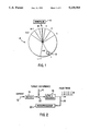
- FIG. 1 is a schematic diagram which illustrates an encoder whose encoder lines are unevenly spaced apart;
- FIG. 2 is a block diagram of an open-loop servo system
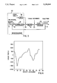
- FIG. 3 is a block diagram of the closed-loop servo system of the present invention.
- FIG. 4 is a graphical illustration of a torque disturbance profile
- FIG. 5 is a graphical illustration of an encoder line error profile
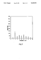
- FIG. 6 is a graphical illustration of the spectra of velocity variations when the torque and time interval tables of the present invention are inactive
- FIG. 7 is a graphical illustration of the spectra of velocity variations when the torque and time interval tables of the present invention are activated.
- FIG. 8 is a flow chart illustrating an algorithm performed by the microprocessor according to the present invention.
- encoder 4 has a plurality of lines (e.g., lines 1, 2, 3, i, i+1, N-2, N-1, N) at spaced intervals.
- Incremental angular encoders may be characterized by the number of lines per revolution (N) on the disc and the placement accuracy of these lines.
- the encoder is usually attached to a rotating shaft. An incremental increase in shaft position ⁇ is measured whenever an encoder line passes stationary detector 6. Detector 6 produces a pulse 8 (FIG. 2) each time an encoder line passes by.
- a home index pulse 10 is used as a reference for an absolute shaft position ⁇ . The home pulse can originate internally or externally of the encoder.
- the spacing between the lines is constant.
- High accuracy, high cost encoders attempt to minimize spacing variations and maximize the number of lines.
- the spacing or intervals between lines varies thus reducing the encoder accuracy since the line spacing variation introduces an error in shaft position and/or velocity detected by the detector 6.
- FIG. 2 illustrates how non-uniform line spacing affects encoder accuracy.
- FIG. 2 is a block diagram of an open loop servo system which includes the encoder 4 of FIG. 1.
- Current 12 is supplied to motor 14 which supplies torque to box 18, box 18 representing a load (e.g. shaft) + encoder 4.
- Encoder 4 outputs a pulse 8 which feeds information to microprocessor 20.
- the torque disturbance 16 acts as a drag on the torque generated by motor 14.
- Pulse train 8 of FIG. 2 is non-uniform or uneven. Assuming a constant current is supplied to motor 14, this uneven pulse train 8 could be the result of drag on the shaft caused by the torque disturbance or could be the result of uneven encoder line spacing.
- the pulse train (for a shaft being driven by a motor supplied by a constant current) can appear non-uniform and varied due to torque disturbances. For example, torque drag can slow the shaft at certain rotational angles of the shaft. The result is the non-uniform time interval pulse train of FIG. 2.
- an uneven encoder pulse train is the result of encoder imperfection (e.g., uneven line spacings) and/or torque disturbances.
- the procedure for separating encoder inaccuracy from torque disturbances uses the data from two independent experiments. The only difference in the two experiments is that the shaft and encoder rotate at velocity ⁇ 1 in the first experiment and at velocity ⁇ 2 in the second experiment. This is accomplished by two different, but constant, test signals (currents) being applied to the motor.
- the below described mathematical analysis can extract a torque profile and a profile of the line spacings (i.e., angular distance between the lines of the encoder) to determine the actual positioning of the lines of the encoder for a predetermined number of microprocessor clock pulses (the line spacing profile) and the rotational positions of the shaft where torque drag is a significant factor (the torque profile).
- a look-up table of set points is generated to determine how many clock pulses or counts the microprocessor should detect between each line of the encoder for a desired speed setting.
- the microprocessor 20 detects 11 counts during this interval, by utilizing its look-up table the microprocessor realizes that the speed is one count off and a signal can be sent to momentarily increase the speed of the motor 20 so overall constant speed is maintained. Conversely, if fewer counts between encoder lines are detected than should be for a given speed, the microprocessor can momentarily decrease the speed of the motor. Also, by knowing the angle or position in the rotating cycle of the shaft that the torque disturbances occur, the microprocessor can selectively send a signal to the motor to counteract the torque disturbances at the appropriate rotational position of the shaft.
- the mathematical analysis conducted by the microprocessor for separating and identifying encoder error and torque disturbance is described below.
- the disturbance torque depends on the motor position and velocity, and has the form ##EQU4##
- the motor/load i.e., motor, shaft and encoder
- variations of ⁇ o are small compared to ⁇ i.
- ⁇ T N+1 - ⁇ T is a measurement of the drift.
- the time interval measurements were corrected by removing it according to: ##EQU5## where: ⁇ T i , j corr corrected time interval measurement (drift removed)
- a pancake dc motor was used to drive a shaft mounted on bearings.
- the main disturbance torque was due to the brushes in the motor and the friction of the bearings.
- the angular position was measured with an eighty tooth gear acting as an encoder.
- a capacitive transducer measured a gear tooth passing and associated circuitry generated a pulse.
- At the other end of the shaft a higher accuracy encoder was mounted.
- the sole purpose of the higher accuracy encoder was to measure the improvement in accuracy of the autocalibrated 80 tooth gear.
- the time interval between pulses was converted to a digital count with a counter circuit and the count was read by a Motorola 68008 computer, which also provided the computational capabilities.
- Output was through a 12 bit D/A converter and a power amplifier to drive the motor.
- pulse train 8 is fed back to microprocessor 20.
- Set point table data 32 is summed at summation point 30 with the information contained in pulse train 8 and the combined information is forwarded to controller 28.
- a torque disturbance removal signal 26 is combined with the output of controller 28 at summation point 24 and the output signal of controller 28 and torque removal signal 26 are fed to motor 14 which drives the shaft of the encoder (represented by box 18). The torque of motor 14 is combined with torque disturbance 16 at summation point 22.
- the microprocessor 20 performing the autocalibration, it also serves as the closed loop controller 28.
- FIG. 8 is a flow chart illustrating the algorithm performed by microprocessor 20/controller 28.
- the encoder is initially calibrated in step 31 by rotating the shaft at the relatively slow and fast (first and second) predetermined constant speeds.
- the profile of torque disturbances is generated in step 33 from the pulse train obtained when rotating the shaft at the slow (first) predetermined constant speed, and the profile of line spacings is generated in step 35 from the pulse train obtained when rotating the shaft at the relatively faster (second) predetermined constant speed.
- a speed is set (step 36) for the shaft on which the encoder is positioned.
- Home pulse 10 and detector 6 send information to the microprocessor so that the angular position of the shaft at any given time is known (step 38).
- step 40 From the torque profile developed from the experiments conducted, it is known where and when in the rotational cycle of the shaft torque disturbances occur (step 40). If a torque disturbance occurs, a signal is sent from the microprocessor to the motor to counteract the torque disturbance (step 44) so that the speed of the shaft will not be affected from the torque disturbance.
- microprocessor 20 As a further result of the experiments and calculations made from the data accumulated in the experiments, microprocessor 20 generates a look-up table which corresponds to the location of set points (i.e., the actual location of encoder lines on the encoder). At a given speed the microprocessor will have a determinable number of clock pulses between set points (step 42). If the count of clock pulses between set points is other than it should be for a given speed (step 46), a signal is sent to the motor 14 to selectively adjust the speed so that the constant desired speed is realized (step 48).
- ⁇ T s nominal time interval setpoint
- ⁇ i-1 encoder line spacing between encoder line (i-1) and (i-2);
- ⁇ 0 nominal encoder line spacing
- the ratio of actual encoder line spacing to the nominal spacing should equal the ratio of the time table interval setpoint to nominal time interval setpoint.
- Measured disturbance torque profile is shown in FIG. 4.
- the accuracy of this measurement was checked by rotating the encoder 180° on the shaft.
- the torque disturbance profile shifted N/2 encoder lines, whereas the encoder line profile remained in the same position relative to the home/index pulse.
- the encoder line error profile is shown in FIG. 5.
- FIGS. 6 and 7 Comparison of the spectra of time interval (velocity variations) with the torque and time interval tables, inactive and active, are shown in FIGS. 6 and 7 respectively. These measurements were done by measuring time interval variations of the high accuracy encoder with the microprocessor performing the closed loop control.
- the graphs of FIGS. 6 and 7 demonstrate that the autocalibration technique of the present invention improved velocity variations by a factor of 4-5 in the previously low accuracy (80 tooth gear) encoder.
- the torque on the motor has a velocity dependent component M and a position dependent component P. It is assumed that these effects are independent so that the torque on the motor may be written as: ##EQU7##
- Q is a constant torque that is proportional to the nominal current.
- the constant bias portion of the resisting torque is included as part of the function P so that the function M is periodic and has a mean value of zero.
- this function M models mechanical and electromechanical asymmetries (brush commutation, friction variations, bearing runout, etc.). If one assumes that the motor load moves as a rigid body, then the equation of motion is ##EQU8## where J is the moment of inertia of the system.
- ⁇ frequency of input signal.
- Discrete time filter algorithms exhibit an equivalent phase shift.
- equation A2 Discrete time filter algorithms
- the procedure consists of first feeding the time series forward through the algorithm and, then, feeding the same time series backward through the algorithm. This cancels positive and negative phase shift while filtering higher frequencies with second order roll-off.
- discrete points which can be programmed into the filter algorithm:
- the time series is first extended and, after filtering, the middle part is used as the filtered output
Abstract
Description
Δθ.sub.i =Δθ.sub.0 +εΦ.sub.i and ΔT.sub.ij =ΔT.sub.oj +εtj; ε<<1 (a9)
Y.sub.i =ay.sub.i-1 +(1-a)x.sub.i (A 2)
Φ=-arctan ωτ
x.sub.i i=1, . . . N
X.sub.i i=1 , . . . N
______________________________________
use filter  Y.sub.i = aY.sub.i-1 + (1 - a)X.sub.i
                             i = 2, . . . 3N
with initial condition
            Y.sub.i = X.sub.i
invert tie series
            Z.sub.i = Y.sub.3N+1-i
                             i + 1,2, . . . 3N
use filter  Vi = aV.sub.i-1 + (1 - a)Z.sub.i
                             i = 2, . . . 3N
with initial condition
            V.sub.1 = Z.sub.i
use middle part
            U.sub.i = V.sub.2N+1-i
                             i = 1, . . . N
of series
______________________________________
Claims (4)
Priority Applications (1)
| Application Number | Priority Date | Filing Date | Title |
|---|---|---|---|
| US07/560,813 US5138564A (en) | 1990-07-31 | 1990-07-31 | Automatic encoder calibration |
Applications Claiming Priority (1)
| Application Number | Priority Date | Filing Date | Title |
|---|---|---|---|
| US07/560,813 US5138564A (en) | 1990-07-31 | 1990-07-31 | Automatic encoder calibration |
Publications (1)
| Publication Number | Publication Date |
|---|---|
| US5138564A true US5138564A (en) | 1992-08-11 |
Family
ID=24239497
Family Applications (1)
| Application Number | Title | Priority Date | Filing Date |
|---|---|---|---|
| US07/560,813 Expired - Lifetime US5138564A (en) | 1990-07-31 | 1990-07-31 | Automatic encoder calibration |
Country Status (1)
| Country | Link |
|---|---|
| US (1) | US5138564A (en) |
Cited By (33)
| Publication number | Priority date | Publication date | Assignee | Title |
|---|---|---|---|---|
| US5305241A (en) * | 1990-09-17 | 1994-04-19 | Okuma Corporation | Error correcting apparatus in position detection |
| US5327360A (en) * | 1992-09-24 | 1994-07-05 | United Technologies Corporation | Measuring relative deflection of interspaced toothed wheels on a less than once per revolution basis |
| US5432502A (en) * | 1993-07-15 | 1995-07-11 | Milliken Research Corporation | Method and apparatus for monitoring signals from transducers and optical encoders |
| US5440213A (en) * | 1989-12-26 | 1995-08-08 | Fanuc, Ltd. | Collision detecting method using an observer |
| US5471054A (en) * | 1991-09-30 | 1995-11-28 | Nf. T&M. Systems, Inc. | Encoder for providing calibrated measurement capability of rotation or linear movement of an object, label medium and an optical identification system |
| US5723965A (en) * | 1995-12-28 | 1998-03-03 | Samsung Electronics Co., Ltd. | Velocity control method and apparatus for servo motors |
| US5796228A (en) * | 1996-09-04 | 1998-08-18 | Mitsubishi Denki Kabushiki Kaisha | Method of controlling rotary magnet multi-phase synchronous motor and control therefor |
| US5932986A (en) * | 1997-03-05 | 1999-08-03 | Whedco, Inc. | Precise control of the rotational velocity of brushless alternating current electric servo motors |
| US6215119B1 (en) | 1999-01-19 | 2001-04-10 | Xerox Corporation | Dual sensor encoder to counter eccentricity errors |
| US6336362B1 (en) | 1998-01-22 | 2002-01-08 | Roy A. Duenas | Method and system for measuring and remotely reporting the liquid level of tanks and the usage thereof |
| US6356219B1 (en) | 2001-03-05 | 2002-03-12 | Aerotech, Inc. | Calibrated encoder multiplier |
| US6415237B1 (en) * | 1999-10-12 | 2002-07-02 | Texas Instruments Incorporated | Electronic correction for rotary transducer spin frequency noise |
| US20030101611A1 (en) * | 2001-11-05 | 2003-06-05 | Bueno Chrispatrick A. | Siding installation tool, kit and method |
| WO2003055077A2 (en) * | 2001-11-02 | 2003-07-03 | Microe Systems Corporation | Encoder self-calibration apparatus and method |
| US20040163469A1 (en) * | 2001-09-07 | 2004-08-26 | Ralf Bohnig | Method for detecting rotational speed |
| US20040188601A1 (en) * | 2003-03-31 | 2004-09-30 | Council Of Scientific And Industrial Research | Opto-electronic device for angle generation of ultrasonic probe |
| US7437201B2 (en) | 2003-01-14 | 2008-10-14 | Cullen Christopher P | Electric motor controller |
| US20090030638A1 (en) * | 2007-07-06 | 2009-01-29 | The University Of British Columbia | Self-calibration method and apparatus for on-axis rotary encoders |
| US20110054508A1 (en) * | 2009-08-31 | 2011-03-03 | Jiansheng Zhou | Pneumatic Pressure Output Control by Drive Valve Duty Cycle Calibration |
| US20110051170A1 (en) * | 2009-08-27 | 2011-03-03 | Xerox Corporation | Synchronization of variation within components to reduce perceptible image quality defects |
| US20110144675A1 (en) * | 2009-12-10 | 2011-06-16 | Gao Shawn X | Systems and Methods for Dynamic Pneumatic Valve Driver |
| US20110144813A1 (en) * | 2009-12-10 | 2011-06-16 | Daryush Agahi | Systems and Methods for Dynamic FeedForward |
| US20110284508A1 (en) * | 2010-05-21 | 2011-11-24 | Kabushiki Kaisha Toshiba | Welding system and welding method |
| US20110297655A1 (en) * | 2010-06-03 | 2011-12-08 | Canon Kabushiki Kaisha | Mirror angular-positioning apparatus and processing apparatus |
| US20130141711A1 (en) * | 2011-12-02 | 2013-06-06 | K-Space Associates, Inc. | Non-contact, optical sensor for synchronizing to free rotating sample platens with asymmetry |
| US8821524B2 (en) | 2010-05-27 | 2014-09-02 | Alcon Research, Ltd. | Feedback control of on/off pneumatic actuators |
| WO2014188894A1 (en) | 2013-05-21 | 2014-11-27 | Mitsubishi Electric Corporation | Method for self-calibrating a rotary encoder |
| US9060841B2 (en) | 2011-08-31 | 2015-06-23 | Alcon Research, Ltd. | Enhanced flow vitrectomy probe |
| US9217731B2 (en) | 2010-05-21 | 2015-12-22 | Kabushiki Kaisha Toshiba | Welding inspection method and apparatus thereof |
| US9423281B2 (en) | 2012-02-07 | 2016-08-23 | Mitsubishi Electric Research Laboratories, Inc. | Self-calibrating single track absolute rotary encoder |
| WO2021228860A1 (en) | 2020-05-15 | 2021-11-18 | Ixblue | Method for estimating angular errors of angle coders in precision rotary devices, device |
| WO2021255600A1 (en) | 2020-06-18 | 2021-12-23 | Synapticon GmbH | Engine controller with improved angle of rotation accuracy |
| EP4343296A1 (en) * | 2022-09-23 | 2024-03-27 | NTN Europe | Method for determining a torque applied between two rotating members |
Citations (14)
| Publication number | Priority date | Publication date | Assignee | Title |
|---|---|---|---|---|
| US3998088A (en) * | 1975-11-12 | 1976-12-21 | The United States Of America As Represented By The Secretary Of The Air Force | Testing apparatus for incremental shaft encoder |
| US4216419A (en) * | 1977-10-24 | 1980-08-05 | U.S. Philips Corporation | Tachometer system |
| US4224515A (en) * | 1978-10-27 | 1980-09-23 | The United States Of America As Represented By The Secretary Of The Air Force | High accuracy optical shaft encoder system |
| US4581713A (en) * | 1982-04-15 | 1986-04-08 | Itt Industries, Inc. | Method of and arrangement for producing numerical values proportional to the frequency of measured pulses of a measured pulse train |
| US4593193A (en) * | 1983-05-31 | 1986-06-03 | Rca Corporation | Apparatus and method for generating calibrated optical encoder pulses |
| US4633224A (en) * | 1985-05-06 | 1986-12-30 | Caterpillar Inc. | Absolute and incremental optical encoder |
| US4792678A (en) * | 1986-10-02 | 1988-12-20 | Dr. Johannes Heidenhain Gmbh | Photoelectric angle measuring device |
| US4803354A (en) * | 1986-04-09 | 1989-02-07 | Hitachi Medical Corp. | Circuit for correcting output phase of rotary encoder |
| US4806752A (en) * | 1986-12-10 | 1989-02-21 | Dr. Johannes Heidenhain Gmbh | Incremental or absolute rotation encoder with a clamping device |
| US4858158A (en) * | 1986-12-22 | 1989-08-15 | Diesel Kiki Co., Ltd. | Apparatus and method for converting rotation angle width into time width |
| US4873655A (en) * | 1987-08-21 | 1989-10-10 | Board Of Regents, The University Of Texas System | Sensor conditioning method and apparatus |
| US4959797A (en) * | 1987-12-11 | 1990-09-25 | Tensor Development, Inc. | System for tightening threaded fastener assemblies |
| US4972332A (en) * | 1987-07-28 | 1990-11-20 | Caterpillar Inc. | Apparatus for determining the speed, angular position and direction of rotation of a rotatable shaft |
| US5016187A (en) * | 1989-01-17 | 1991-05-14 | Tokheim Corporation | Linearized turbine flow meter for fuel dispensers |
-
1990
- 1990-07-31 US US07/560,813 patent/US5138564A/en not_active Expired - Lifetime
Patent Citations (14)
| Publication number | Priority date | Publication date | Assignee | Title |
|---|---|---|---|---|
| US3998088A (en) * | 1975-11-12 | 1976-12-21 | The United States Of America As Represented By The Secretary Of The Air Force | Testing apparatus for incremental shaft encoder |
| US4216419A (en) * | 1977-10-24 | 1980-08-05 | U.S. Philips Corporation | Tachometer system |
| US4224515A (en) * | 1978-10-27 | 1980-09-23 | The United States Of America As Represented By The Secretary Of The Air Force | High accuracy optical shaft encoder system |
| US4581713A (en) * | 1982-04-15 | 1986-04-08 | Itt Industries, Inc. | Method of and arrangement for producing numerical values proportional to the frequency of measured pulses of a measured pulse train |
| US4593193A (en) * | 1983-05-31 | 1986-06-03 | Rca Corporation | Apparatus and method for generating calibrated optical encoder pulses |
| US4633224A (en) * | 1985-05-06 | 1986-12-30 | Caterpillar Inc. | Absolute and incremental optical encoder |
| US4803354A (en) * | 1986-04-09 | 1989-02-07 | Hitachi Medical Corp. | Circuit for correcting output phase of rotary encoder |
| US4792678A (en) * | 1986-10-02 | 1988-12-20 | Dr. Johannes Heidenhain Gmbh | Photoelectric angle measuring device |
| US4806752A (en) * | 1986-12-10 | 1989-02-21 | Dr. Johannes Heidenhain Gmbh | Incremental or absolute rotation encoder with a clamping device |
| US4858158A (en) * | 1986-12-22 | 1989-08-15 | Diesel Kiki Co., Ltd. | Apparatus and method for converting rotation angle width into time width |
| US4972332A (en) * | 1987-07-28 | 1990-11-20 | Caterpillar Inc. | Apparatus for determining the speed, angular position and direction of rotation of a rotatable shaft |
| US4873655A (en) * | 1987-08-21 | 1989-10-10 | Board Of Regents, The University Of Texas System | Sensor conditioning method and apparatus |
| US4959797A (en) * | 1987-12-11 | 1990-09-25 | Tensor Development, Inc. | System for tightening threaded fastener assemblies |
| US5016187A (en) * | 1989-01-17 | 1991-05-14 | Tokheim Corporation | Linearized turbine flow meter for fuel dispensers |
Cited By (60)
| Publication number | Priority date | Publication date | Assignee | Title |
|---|---|---|---|---|
| US5440213A (en) * | 1989-12-26 | 1995-08-08 | Fanuc, Ltd. | Collision detecting method using an observer |
| US5305241A (en) * | 1990-09-17 | 1994-04-19 | Okuma Corporation | Error correcting apparatus in position detection |
| US5471054A (en) * | 1991-09-30 | 1995-11-28 | Nf. T&M. Systems, Inc. | Encoder for providing calibrated measurement capability of rotation or linear movement of an object, label medium and an optical identification system |
| US5327360A (en) * | 1992-09-24 | 1994-07-05 | United Technologies Corporation | Measuring relative deflection of interspaced toothed wheels on a less than once per revolution basis |
| US5432502A (en) * | 1993-07-15 | 1995-07-11 | Milliken Research Corporation | Method and apparatus for monitoring signals from transducers and optical encoders |
| US5723965A (en) * | 1995-12-28 | 1998-03-03 | Samsung Electronics Co., Ltd. | Velocity control method and apparatus for servo motors |
| US5796228A (en) * | 1996-09-04 | 1998-08-18 | Mitsubishi Denki Kabushiki Kaisha | Method of controlling rotary magnet multi-phase synchronous motor and control therefor |
| US5932986A (en) * | 1997-03-05 | 1999-08-03 | Whedco, Inc. | Precise control of the rotational velocity of brushless alternating current electric servo motors |
| US6336362B1 (en) | 1998-01-22 | 2002-01-08 | Roy A. Duenas | Method and system for measuring and remotely reporting the liquid level of tanks and the usage thereof |
| US6215119B1 (en) | 1999-01-19 | 2001-04-10 | Xerox Corporation | Dual sensor encoder to counter eccentricity errors |
| US6415237B1 (en) * | 1999-10-12 | 2002-07-02 | Texas Instruments Incorporated | Electronic correction for rotary transducer spin frequency noise |
| US6501403B2 (en) * | 2001-03-05 | 2002-12-31 | Aerotech, Inc. | Calibrated encoder multiplier |
| US6356219B1 (en) | 2001-03-05 | 2002-03-12 | Aerotech, Inc. | Calibrated encoder multiplier |
| US20040163469A1 (en) * | 2001-09-07 | 2004-08-26 | Ralf Bohnig | Method for detecting rotational speed |
| US7096136B2 (en) * | 2001-09-07 | 2006-08-22 | Siemens Aktiengesellschaft | Method for detecting rotational speed |
| US6897435B2 (en) | 2001-11-02 | 2005-05-24 | Gsi Lumonics Corporation | Encoder self-callibration apparatus and method |
| WO2003055077A3 (en) * | 2001-11-02 | 2004-04-01 | Microe Systems Corp | Encoder self-calibration apparatus and method |
| WO2003055077A2 (en) * | 2001-11-02 | 2003-07-03 | Microe Systems Corporation | Encoder self-calibration apparatus and method |
| US7193205B2 (en) | 2001-11-02 | 2007-03-20 | Gsi Group Corporation | Optical encoder with burst generator for generating burst output signals |
| US20050194524A1 (en) * | 2001-11-02 | 2005-09-08 | Gsi Lumonics Corporation | Encoder self-calibration apparatus and method |
| CN100438339C (en) * | 2001-11-02 | 2008-11-26 | Gsi集团公司 | Encoder self-calibration apparatus and method |
| US7075057B2 (en) | 2001-11-02 | 2006-07-11 | Gsi Group Corporation | Method of generating an index signal for an optical encoder |
| US20060186360A1 (en) * | 2001-11-02 | 2006-08-24 | Gsi Group Corporation | Optical encoder with burst generator for generating burst output signals |
| EP1712467A2 (en) * | 2001-11-02 | 2006-10-18 | GSI Group Corporation | Encoder self-calibration apparatus and method |
| EP1712467A3 (en) * | 2001-11-02 | 2006-11-08 | GSI Group Corporation | Encoder self-calibration apparatus and method |
| US20030101611A1 (en) * | 2001-11-05 | 2003-06-05 | Bueno Chrispatrick A. | Siding installation tool, kit and method |
| US7606624B2 (en) | 2003-01-14 | 2009-10-20 | Cullen Christopher P | Self-commissioning electronic motor controller determination |
| US20090021205A1 (en) * | 2003-01-14 | 2009-01-22 | Cullen Christopher P | Electronic motor controller |
| US20100036510A1 (en) * | 2003-01-14 | 2010-02-11 | Christopher Cullen | Electronic motor controller |
| US7437201B2 (en) | 2003-01-14 | 2008-10-14 | Cullen Christopher P | Electric motor controller |
| US6946648B2 (en) * | 2003-03-31 | 2005-09-20 | Council Of Scientific And Industrial Research | Opto-electronic device for angle generation of ultrasonic probe |
| US20040188601A1 (en) * | 2003-03-31 | 2004-09-30 | Council Of Scientific And Industrial Research | Opto-electronic device for angle generation of ultrasonic probe |
| US20090030638A1 (en) * | 2007-07-06 | 2009-01-29 | The University Of British Columbia | Self-calibration method and apparatus for on-axis rotary encoders |
| US7840372B2 (en) | 2007-07-06 | 2010-11-23 | The University Of British Columbia | Self-calibration method and apparatus for on-axis rotary encoders |
| US8320013B2 (en) | 2009-08-27 | 2012-11-27 | Xerox Corporation | Synchronization of variation within components to reduce perceptible image quality defects |
| US20110051170A1 (en) * | 2009-08-27 | 2011-03-03 | Xerox Corporation | Synchronization of variation within components to reduce perceptible image quality defects |
| US20110054508A1 (en) * | 2009-08-31 | 2011-03-03 | Jiansheng Zhou | Pneumatic Pressure Output Control by Drive Valve Duty Cycle Calibration |
| US8818564B2 (en) | 2009-08-31 | 2014-08-26 | Alcon Research, Ltd. | Pneumatic pressure output control by drive valve duty cycle calibration |
| US8666556B2 (en) * | 2009-12-10 | 2014-03-04 | Alcon Research, Ltd. | Systems and methods for dynamic feedforward |
| CN102652290A (en) * | 2009-12-10 | 2012-08-29 | 爱尔康研究有限公司 | Methods for adaptative feedforward control in surgical system |
| US20110144813A1 (en) * | 2009-12-10 | 2011-06-16 | Daryush Agahi | Systems and Methods for Dynamic FeedForward |
| US8728108B2 (en) | 2009-12-10 | 2014-05-20 | Alcon Research, Ltd. | Systems and methods for dynamic pneumatic valve driver |
| US20110144675A1 (en) * | 2009-12-10 | 2011-06-16 | Gao Shawn X | Systems and Methods for Dynamic Pneumatic Valve Driver |
| CN102652290B (en) * | 2009-12-10 | 2015-04-29 | 爱尔康研究有限公司 | Methods for adaptative feedforward control in surgical system |
| US20110284508A1 (en) * | 2010-05-21 | 2011-11-24 | Kabushiki Kaisha Toshiba | Welding system and welding method |
| US9217731B2 (en) | 2010-05-21 | 2015-12-22 | Kabushiki Kaisha Toshiba | Welding inspection method and apparatus thereof |
| US8821524B2 (en) | 2010-05-27 | 2014-09-02 | Alcon Research, Ltd. | Feedback control of on/off pneumatic actuators |
| US9933616B2 (en) * | 2010-06-03 | 2018-04-03 | Canon Kabushiki Kaisha | Mirror angular-positioning apparatus and processing apparatus |
| US20110297655A1 (en) * | 2010-06-03 | 2011-12-08 | Canon Kabushiki Kaisha | Mirror angular-positioning apparatus and processing apparatus |
| US9060841B2 (en) | 2011-08-31 | 2015-06-23 | Alcon Research, Ltd. | Enhanced flow vitrectomy probe |
| US9030652B2 (en) * | 2011-12-02 | 2015-05-12 | K-Space Associates, Inc. | Non-contact, optical sensor for synchronizing to free rotating sample platens with asymmetry |
| US20130141711A1 (en) * | 2011-12-02 | 2013-06-06 | K-Space Associates, Inc. | Non-contact, optical sensor for synchronizing to free rotating sample platens with asymmetry |
| US9423281B2 (en) | 2012-02-07 | 2016-08-23 | Mitsubishi Electric Research Laboratories, Inc. | Self-calibrating single track absolute rotary encoder |
| WO2014188894A1 (en) | 2013-05-21 | 2014-11-27 | Mitsubishi Electric Corporation | Method for self-calibrating a rotary encoder |
| WO2021228860A1 (en) | 2020-05-15 | 2021-11-18 | Ixblue | Method for estimating angular errors of angle coders in precision rotary devices, device |
| FR3110258A1 (en) * | 2020-05-15 | 2021-11-19 | Ixblue | Method for estimating angular errors of angular encoders in precision rotary devices, device |
| WO2021255600A1 (en) | 2020-06-18 | 2021-12-23 | Synapticon GmbH | Engine controller with improved angle of rotation accuracy |
| DE102020116165A1 (en) | 2020-06-18 | 2021-12-23 | Synapticon GmbH | Motor control device with improved rotation angle accuracy |
| EP4343296A1 (en) * | 2022-09-23 | 2024-03-27 | NTN Europe | Method for determining a torque applied between two rotating members |
| FR3140169A1 (en) * | 2022-09-23 | 2024-03-29 | Ntn-Snr Roulements | Method for determining a torque applied between two rotating members |
Similar Documents
| Publication | Publication Date | Title |
|---|---|---|
| US5138564A (en) | Automatic encoder calibration | |
| US5550685A (en) | Applying an adaptive feed-forward algorithm as a frequency selective filter in a closed loop disk drive servo system in order to compensate for periodic perturbations which otherwise appear in the servo system position error signal | |
| US4125881A (en) | Tape motion control for reel-to-reel drive | |
| KR900009172B1 (en) | Apparatus and method for tape transporting | |
| US4525654A (en) | Tape transport control unit | |
| US5532583A (en) | System and method for calibrating a position sensing system | |
| US6963184B2 (en) | Adaptable spatial notch filter | |
| US4503374A (en) | Speed detection apparatus and method | |
| US4739950A (en) | Constant velocity tape drive system | |
| US4922513A (en) | Rotation control circuit for a hall motor | |
| US4420715A (en) | Apparatus for controlling motor speed | |
| US6396234B1 (en) | Servo control apparatus and servo control method | |
| US20040021971A1 (en) | Compensation for variation in timing skew in a disc drive data storage system | |
| US5306994A (en) | Automatic phase margin compensation control circuit and method for disk drives | |
| US6470291B1 (en) | Velocity feedback measurement method | |
| KR980012819A (en) | Apparatus for calculating the absolute angular position of a rotary motor and a speed control device using the same | |
| EP0439902A2 (en) | Rotary head type magnetic tape apparatus | |
| KR950005179B1 (en) | Digital comb filter | |
| JP2739963B2 (en) | Control device for tape transfer device | |
| JP3122675B2 (en) | Rotation control method | |
| JP3167258B2 (en) | Zero point correction method for belt feeder | |
| KR920009773B1 (en) | Driving reel motor control method and circuit for tape high speed and normal speed | |
| KR950007137B1 (en) | Drum and capstan motor control method of dat | |
| CN117419887B (en) | ABZ type inclination sensor Z signal interference correction method for wind tunnel test environment | |
| US20040041048A1 (en) | Delta velocity tension control for tape |
Legal Events
| Date | Code | Title | Description |
|---|---|---|---|
| AS | Assignment |
Owner name: XEROX CORPORATION, A CORP OF NY, CONNECTICUT Free format text: ASSIGNMENT OF ASSIGNORS INTEREST.;ASSIGNORS:MATHEUS DE JONG, JOANNES N.;WOLF, BARRY;REEL/FRAME:005444/0866 Effective date: 19900827 |
|
| STCF | Information on status: patent grant |
Free format text: PATENTED CASE |
|
| FEPP | Fee payment procedure |
Free format text: PAYOR NUMBER ASSIGNED (ORIGINAL EVENT CODE: ASPN); ENTITY STATUS OF PATENT OWNER: LARGE ENTITY |
|
| FPAY | Fee payment |
Year of fee payment: 4 |
|
| FPAY | Fee payment |
Year of fee payment: 8 |
|
| AS | Assignment |
Owner name: BANK ONE, NA, AS ADMINISTRATIVE AGENT, ILLINOIS Free format text: SECURITY INTEREST;ASSIGNOR:XEROX CORPORATION;REEL/FRAME:013153/0001 Effective date: 20020621 |
|
| AS | Assignment |
Owner name: JPMORGAN CHASE BANK, AS COLLATERAL AGENT, TEXAS Free format text: SECURITY AGREEMENT;ASSIGNOR:XEROX CORPORATION;REEL/FRAME:015134/0476 Effective date: 20030625 Owner name: JPMORGAN CHASE BANK, AS COLLATERAL AGENT,TEXAS Free format text: SECURITY AGREEMENT;ASSIGNOR:XEROX CORPORATION;REEL/FRAME:015134/0476 Effective date: 20030625 |
|
| FPAY | Fee payment |
Year of fee payment: 12 |
|
| AS | Assignment |
Owner name: XEROX CORPORATION, NEW YORK Free format text: RELEASE BY SECURED PARTY;ASSIGNOR:JP MORGAN CHASE BANK, NA;REEL/FRAME:020031/0840 Effective date: 20061204 |
|
| AS | Assignment |
Owner name: XEROX CORPORATION, NEW YORK Free format text: RELEASE BY SECURED PARTY;ASSIGNOR:BANK ONE, NA;REEL/FRAME:020045/0538 Effective date: 20030625 |
|
| AS | Assignment |
Owner name: XEROX CORPORATION, CONNECTICUT Free format text: RELEASE BY SECURED PARTY;ASSIGNOR:JPMORGAN CHASE BANK, N.A. AS SUCCESSOR-IN-INTEREST ADMINISTRATIVE AGENT AND COLLATERAL AGENT TO JPMORGAN CHASE BANK;REEL/FRAME:066728/0193 Effective date: 20220822 |