US5141532A - Thermal modulation inlet for gas chromatography system - Google Patents
Thermal modulation inlet for gas chromatography system Download PDFInfo
- Publication number
- US5141532A US5141532A US07/710,703 US71070391A US5141532A US 5141532 A US5141532 A US 5141532A US 71070391 A US71070391 A US 71070391A US 5141532 A US5141532 A US 5141532A
- Authority
- US
- United States
- Prior art keywords
- sample
- column
- gas chromatography
- sample tube
- components
- Prior art date
- Legal status (The legal status is an assumption and is not a legal conclusion. Google has not performed a legal analysis and makes no representation as to the accuracy of the status listed.)
- Expired - Fee Related
Links
Images
Classifications
-
- G—PHYSICS
- G01—MEASURING; TESTING
- G01N—INVESTIGATING OR ANALYSING MATERIALS BY DETERMINING THEIR CHEMICAL OR PHYSICAL PROPERTIES
- G01N33/00—Investigating or analysing materials by specific methods not covered by groups G01N1/00 - G01N31/00
- G01N33/02—Food
-
- G—PHYSICS
- G01—MEASURING; TESTING
- G01N—INVESTIGATING OR ANALYSING MATERIALS BY DETERMINING THEIR CHEMICAL OR PHYSICAL PROPERTIES
- G01N30/00—Investigating or analysing materials by separation into components using adsorption, absorption or similar phenomena or using ion-exchange, e.g. chromatography or field flow fractionation
- G01N30/02—Column chromatography
- G01N30/26—Conditioning of the fluid carrier; Flow patterns
- G01N30/38—Flow patterns
- G01N30/40—Flow patterns using back flushing
-
- G—PHYSICS
- G01—MEASURING; TESTING
- G01N—INVESTIGATING OR ANALYSING MATERIALS BY DETERMINING THEIR CHEMICAL OR PHYSICAL PROPERTIES
- G01N30/00—Investigating or analysing materials by separation into components using adsorption, absorption or similar phenomena or using ion-exchange, e.g. chromatography or field flow fractionation
- G01N30/02—Column chromatography
- G01N30/04—Preparation or injection of sample to be analysed
- G01N30/06—Preparation
- G01N30/12—Preparation by evaporation
-
- G—PHYSICS
- G01—MEASURING; TESTING
- G01N—INVESTIGATING OR ANALYSING MATERIALS BY DETERMINING THEIR CHEMICAL OR PHYSICAL PROPERTIES
- G01N1/00—Sampling; Preparing specimens for investigation
- G01N1/02—Devices for withdrawing samples
- G01N1/22—Devices for withdrawing samples in the gaseous state
- G01N1/2202—Devices for withdrawing samples in the gaseous state involving separation of sample components during sampling
- G01N1/2214—Devices for withdrawing samples in the gaseous state involving separation of sample components during sampling by sorption
-
- G—PHYSICS
- G01—MEASURING; TESTING
- G01N—INVESTIGATING OR ANALYSING MATERIALS BY DETERMINING THEIR CHEMICAL OR PHYSICAL PROPERTIES
- G01N30/00—Investigating or analysing materials by separation into components using adsorption, absorption or similar phenomena or using ion-exchange, e.g. chromatography or field flow fractionation
- G01N30/02—Column chromatography
- G01N30/04—Preparation or injection of sample to be analysed
- G01N30/06—Preparation
- G01N30/12—Preparation by evaporation
- G01N2030/121—Preparation by evaporation cooling; cold traps
- G01N2030/122—Preparation by evaporation cooling; cold traps cryogenic focusing
-
- G—PHYSICS
- G01—MEASURING; TESTING
- G01N—INVESTIGATING OR ANALYSING MATERIALS BY DETERMINING THEIR CHEMICAL OR PHYSICAL PROPERTIES
- G01N30/00—Investigating or analysing materials by separation into components using adsorption, absorption or similar phenomena or using ion-exchange, e.g. chromatography or field flow fractionation
- G01N30/02—Column chromatography
- G01N30/26—Conditioning of the fluid carrier; Flow patterns
- G01N30/28—Control of physical parameters of the fluid carrier
- G01N30/30—Control of physical parameters of the fluid carrier of temperature
- G01N2030/3046—Control of physical parameters of the fluid carrier of temperature temperature control of column inlet
-
- G—PHYSICS
- G01—MEASURING; TESTING
- G01N—INVESTIGATING OR ANALYSING MATERIALS BY DETERMINING THEIR CHEMICAL OR PHYSICAL PROPERTIES
- G01N30/00—Investigating or analysing materials by separation into components using adsorption, absorption or similar phenomena or using ion-exchange, e.g. chromatography or field flow fractionation
- G01N30/02—Column chromatography
- G01N30/26—Conditioning of the fluid carrier; Flow patterns
- G01N30/38—Flow patterns
- G01N2030/382—Flow patterns flow switching in a single column
- G01N2030/385—Flow patterns flow switching in a single column by switching valves
-
- G—PHYSICS
- G01—MEASURING; TESTING
- G01N—INVESTIGATING OR ANALYSING MATERIALS BY DETERMINING THEIR CHEMICAL OR PHYSICAL PROPERTIES
- G01N30/00—Investigating or analysing materials by separation into components using adsorption, absorption or similar phenomena or using ion-exchange, e.g. chromatography or field flow fractionation
- G01N30/02—Column chromatography
- G01N30/26—Conditioning of the fluid carrier; Flow patterns
- G01N30/38—Flow patterns
- G01N30/40—Flow patterns using back flushing
- G01N2030/405—Flow patterns using back flushing re-concentrating or inverting previous separation
-
- G—PHYSICS
- G01—MEASURING; TESTING
- G01N—INVESTIGATING OR ANALYSING MATERIALS BY DETERMINING THEIR CHEMICAL OR PHYSICAL PROPERTIES
- G01N30/00—Investigating or analysing materials by separation into components using adsorption, absorption or similar phenomena or using ion-exchange, e.g. chromatography or field flow fractionation
- G01N30/02—Column chromatography
- G01N30/26—Conditioning of the fluid carrier; Flow patterns
- G01N30/38—Flow patterns
- G01N30/40—Flow patterns using back flushing
- G01N2030/407—Flow patterns using back flushing carrying out another separation
-
- G—PHYSICS
- G01—MEASURING; TESTING
- G01N—INVESTIGATING OR ANALYSING MATERIALS BY DETERMINING THEIR CHEMICAL OR PHYSICAL PROPERTIES
- G01N30/00—Investigating or analysing materials by separation into components using adsorption, absorption or similar phenomena or using ion-exchange, e.g. chromatography or field flow fractionation
- G01N30/02—Column chromatography
- G01N30/62—Detectors specially adapted therefor
- G01N2030/621—Detectors specially adapted therefor signal-to-noise ratio
- G01N2030/623—Detectors specially adapted therefor signal-to-noise ratio by modulation of sample feed or detector response
Definitions
- This invention relates to an apparatus for gas chromatography, and particularly, to an inlet system for such an apparatus.
- Gas chromatography is a widely employed technique for the separation and analysis of complex mixtures of volatile organic and inorganic compounds.
- the analyte mixture is separated into its components by eluding them from a column having a sorbent by means of moving gas.
- Gas chromatography procedures can be classified into two major divisions; gas-liquid chromatography, and gas-solid chromatography.
- Gas-liquid chromatography is presently the most widely employed type and incorporates a nonvolatile liquid sorbent coated as a thin layer on an inner support structure, generally the inside surface of a capillary tube.
- the moving gas phase called the carrier gas
- the analyte partitions itself between the moving gas phase and the sorbent, and moves through the column at a rate dependent upon the partition coefficient or solubility of the analyte components.
- the analyte is introduced at the entrance end of the column within the moving carrier gas stream.
- a detector for example, a thermal conductivity detector or a flame ionization detector (FID) at the exit end of the column responds to the presence of analyte components.
- FID flame ionization detector
- the flame behavior is monitored through a biased ion detector which, along with associated electronics, produces a chromatogram which is a time versus magnitude trace of the detector output.
- the trace for a complex mixture includes numerous peaks of varying intensity. Since individual constituents of the analyte produces peaks at characteristic times and whose magnitude is a function of their concentration, much information is gained through an evaluation of the chromatogram.
- Gas chromatography systems of the type described above are in widespread use today. Although present systems provide excellent performance and utility, this invention seeks to provide improvements in gas chromatography systems; principally through simplifying the systems and increasing their speed and operational flexibility.
- Conventional gas chromatography system employs a mechanical system for the injection of analyte. For example, mechanical valves, or needles and septum type injection techniques are presently used. Such mechanical techniques contribute to system complexity, both in terms of their presence in the system and their control requirements.
- Conventional gas chromatography apparatuses are also unsatisfactory for high-speed analysis, since the column injection bandwidths are excessively large.
- a gas chromatography system in which no mechanical barriers are used to control the flow of analyte into the system. Instead, a thermal focusing chamber is provided at sub-ambient temperatures which is used as the exclusive means for controlling flow of analyte components into the separation column.
- the analyte stream continually flows into the thermal focusing chamber. Its introduction into the separation column, however, is controlled by the temperature of the sample tube in the thermal focusing chamber.
- the injection system of this invention allows the high speed, repetitive sampling of a continuously flowing sample stream.
- This invention relatively simple mixtures can be separated faster than with current commercial apparatuses. Since the system has no moving parts, it is very rugged, and can operate for many cycles with minimal maintenance.
- the flexibility of the inlet system according to this invention is demonstrated by the variety of optional modes it supports.
- the system is also capable of ambient and sub-ambient pressure inlet with vacuum outlet, and with vacuum backflush features. All of these modes of operation can be computer controlled.
- This invention provides potential applications for numerous gas chromatography procedures, including those practiced by process engineers and chemists, industrial hygiene workers, and others interested in the continuous monitoring of volatile organic mixtures.
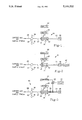
- FIG. 1 is a schematic view of a gas chromatography system in accordance with a first embodiment of this invention for use with a sample introduced into the system at a positive pressure and the column outlet vented to atmosphere.
- FIG. 2 is a schematic diagram of a gas chromatography system in accordance with a second embodiment of this invention intended for continuous ambient pressure sensing through use of a vacuum source at the column outlet.
- FIG. 3 is a schematic diagram of a gas chromatography system in accordance with a third embodiment of this invention providing a vacuum assisted backflush capability.
- Gas chromatography system 10 in accordance with a first embodiment of this invention is shown in FIG. 1 and is designated there by reference number 10.
- Gas chromatography system 10 includes a thermal focusing chamber or trap 12 having inlets and outlets 14 and 16, respectively, for conducting the flow of a cryogenic gas such as nitrogen.
- a short length of metal capillary sample tube 18 passes through chamber 12 and conducts the analyte through the chamber.
- Heater circuit 20 is connected to metal sample tube 18 via a pair of conductive blocks (or by direct soldering) and provides a short duration, high current pulse which causes extremely rapid heating of the sample tube.
- One such heater circuit which can be employed in conjunction with this invention is a multi-stage capacitive discharge circuit such as is described in the parent of this application.
- Computer 22 controls operation of heater circuit 20 in accordance with a pre-specified operating sequence.
- Capillary tube 18 is connected to chromatography separation column 24 of conventional construction. Materials which elude from column 24 are sensed by flame ionization detector (FID) 26. As described previously, when components of the analyte pass through FID, charged species are formed which are detected by an electrometer.
- FID flame ionization detector
- a carrier gas such as hydrogen with the sample stream entrained on it enters the system at inlet 28.
- the pressure of the carrier gas and sample stream is continuously measured by monitor 30.
- Sample bulb 32 causes a small portion of the carrier gas and sample stream to be directed through chamber inlet conduit 34.
- a flow restrictor which may be in the form of a short, small caliber piece of fused silica capillary tube 36 is provided so that the portion of the carrier gas and sample stream which is not flowing through chamber inlet conduit 34 is continually vented.
- the level of restriction imposed by restrictor 36 is selected to provide a desired flow rate into bulb 32.
- the carrier gas and sample stream are directed through sample bulb 32 continuously.
- sample is continuously delivered to chamber 12.
- cold nitrogen gas continually circulates through thermal focusing chamber 12
- the sample stream entering becomes trapped in tube 18 through condensation.
- a pulse of current is generated by circuit 20 thereby heating capillary tube 18 and causing the condensate to be vaporized and injected into column 24.
- heater circuit 20 resistively heats metal tube 18 in a few milliseconds, the sample is introduced as a very narrow sample plug into column 24 for separation.
- the metal tube 18 Upon completion of a heating cycle, the metal tube 18 begins to cool and within a few seconds, its temperature returns to a value sufficiently low to ensure complete collection of the sample.
- a series of high speed chromatagrams can be generated by consecutively alternating the heating and cooling cycles.
- the sample vapor is delivered continuously to thermal modulation chamber 12 with the thermal modulation technique, "breakthrough" of sample vapor arriving at the chamber just after heating is inevitable (i.e. direct passage through the focusing chamber). As thermal focusing chamber 12 cools, the breakthrough gradually decreases until the trap temperature necessary for quantitative trapping is again achieved. For typical operation, the sample collection interval between injections is a few seconds and the injection bandwidth when sample tube 18 is heated is a few milliseconds. Thus the sample injected from sample tube 18 is enriched by about a factor of a thousand, and the detector signal from the breakthrough sample vapor may be insignificant.
- metal capillary tube After injection, current flow through metal capillary tube is stopped, causing it to cool and thus condense incoming sample components.
- the temperature of tube may, however, be adjusted to prevent certain highly volatile components of the mixture from being trapped. This is possible since higher initial temperatures for chamber 12 provide slower cooling rates and the more volatile components require significantly lower condensation temperatures.
- FIG. 2 shows a second embodiment of a gas chromatography system in accordance with this invention which is generally designated by reference number 40.
- System 40 has many components which are identical to those of system 10 and are accordingly identified by like reference numbers.
- Gas chromatography system 40 differs from system 10 in that restrictor 36 is eliminated. Instead, a vacuum source 42 acts beyond detector 26, causing the system to draw sample at atmospheric pressure. For example, this system could be implemented as an air quality "sniffing" probe. Operation of system 40 proceeds like that of system 10 in that alternating heating and cooling cycles of the sample within thermal focusing chamber 12 occur, causing alternative trapping and injection of the components of the sample being evaluated.
- FIG. 3 illustrates gas chromatography system 50 according to a third embodiment of this invention.
- System 50 is generally consistent with that shown in FIG. 1, except that a vacuum backflush system in incorporated.
- Vacuum source 42 communicates with the inlet of column 24 and is controlled through interface unit 52 by computer 22.
- Interface unit 52 is preferably coupled to a pneumatically operated micro gas valve.
- system 50 is adapted to be used in conjunction with a carrier gas and sample stream supplied at a pressure above atmospheric which thus drives the carrier gas and sample stream through the system with the outlet of column 24 exposed to atmosphere.
- Vacuum source 42 is periodically connected with the inlet end of column 24 causing a reverse migration of components on the column.
- Restrictor 38 is provided to ensure reverse direction fluid flow through column 24.
- vacuum source 42 communicates with the column to backflush the system. This process is preferably accomplished while thermal focusing chamber 12 is again at a low temperature, causing the next sample for injection to be simultaneously trapped while the backflush operation is occurring.
- Sample tube 18 comprised a tube made of 70% Cu and 30% Ni, having a length of 25 cm and a 0.30 mm inside diameter.
- the experimental prototype column 24 comprised a 200 cm long, 0.25-mm i.d. fused silica capillary with a 0.1-micro m thick methyl silicone stationary phase (DB-5).
- the sample tube 18 was clamped between a pair of copper conductive blocks heated by 150 watt heating cartridges with Omega model CN9111J temperature controllers
- Heater circuit 20 comprised a capacitive discharge system with 7 L-C sections, 2000 micro-F and 107 micro-H each, 0-80 V.
- the nitrogen gas passing through thermal focusing chamber 12 provided a -90° C. temperature.
- the restrictor 38 comprised a 38-cm long, 0.1-mm i.d. deactivated fused silica capillary.
- the valves which were controlled through interface unit 52 was an SGE micro pneumatic on-off valve in "L" configuration with a 50 mm stem, and a Valco solenoid valve model H55P18DIA.
- Vacuum source 42 comprised a Cenco Hyvac 7, two-stage pump.
- the experimental prototype was evaluated using a mixture containing n-heptane, toluene and p-xylene vapor in hydrogen carrier gas at concentrations of 13, 25 and 18 micro-L/L, respectively.
- metal sample tube 18 received a heating pulse every 10.4 seconds.
- the temperature of thermal focusing chamber 12 range from -95° C. just before the heating pulse to about 60° C.
- Backflush flow for system 50 was initiated 5.0 s after sample injection and was continued for 3.0 s.
Abstract
Description
Claims (9)
Priority Applications (8)
| Application Number | Priority Date | Filing Date | Title |
|---|---|---|---|
| US07/710,703 US5141532A (en) | 1990-09-28 | 1991-06-05 | Thermal modulation inlet for gas chromatography system |
| US07/817,306 US5205845A (en) | 1990-09-28 | 1992-01-06 | Mechanical gas chromatography injection valves and column multiplexing techniques |
| EP92305018A EP0525950B1 (en) | 1991-06-05 | 1992-06-01 | Thermal modulation inlet system for gas chromatography |
| DE69205910T DE69205910T2 (en) | 1991-06-05 | 1992-06-01 | Thermal modulation inlet system for gas chromatography. |
| JP4170185A JP2684540B2 (en) | 1991-06-05 | 1992-06-03 | Gas chromatography apparatus and method |
| CA002070448A CA2070448C (en) | 1991-06-05 | 1992-06-04 | Thermal modulation inlet system for gas chromatography |
| KR1019920009704A KR100212177B1 (en) | 1991-06-05 | 1992-06-04 | Thermal modulation inlet system fpr gas chromatography |
| US07/975,289 US5281256A (en) | 1990-09-28 | 1992-11-12 | Gas chromatography system with column bifurcation and tunable selectivity |
Applications Claiming Priority (2)
| Application Number | Priority Date | Filing Date | Title |
|---|---|---|---|
| US07/590,174 US5096471A (en) | 1990-09-28 | 1990-09-28 | Gas chromatography system and methods |
| US07/710,703 US5141532A (en) | 1990-09-28 | 1991-06-05 | Thermal modulation inlet for gas chromatography system |
Related Parent Applications (1)
| Application Number | Title | Priority Date | Filing Date |
|---|---|---|---|
| US07/590,174 Continuation-In-Part US5096471A (en) | 1990-09-28 | 1990-09-28 | Gas chromatography system and methods |
Related Child Applications (2)
| Application Number | Title | Priority Date | Filing Date |
|---|---|---|---|
| US07/817,306 Continuation-In-Part US5205845A (en) | 1990-09-28 | 1992-01-06 | Mechanical gas chromatography injection valves and column multiplexing techniques |
| US07/975,289 Continuation-In-Part US5281256A (en) | 1990-09-28 | 1992-11-12 | Gas chromatography system with column bifurcation and tunable selectivity |
Publications (1)
| Publication Number | Publication Date |
|---|---|
| US5141532A true US5141532A (en) | 1992-08-25 |
Family
ID=24855161
Family Applications (1)
| Application Number | Title | Priority Date | Filing Date |
|---|---|---|---|
| US07/710,703 Expired - Fee Related US5141532A (en) | 1990-09-28 | 1991-06-05 | Thermal modulation inlet for gas chromatography system |
Country Status (6)
| Country | Link |
|---|---|
| US (1) | US5141532A (en) |
| EP (1) | EP0525950B1 (en) |
| JP (1) | JP2684540B2 (en) |
| KR (1) | KR100212177B1 (en) |
| CA (1) | CA2070448C (en) |
| DE (1) | DE69205910T2 (en) |
Cited By (31)
| Publication number | Priority date | Publication date | Assignee | Title |
|---|---|---|---|---|
| US5281256A (en) * | 1990-09-28 | 1994-01-25 | Regents Of The University Of Michigan | Gas chromatography system with column bifurcation and tunable selectivity |
| US5288310A (en) * | 1992-09-30 | 1994-02-22 | The Regents Of The University Of Michigan | Adsorbent trap for gas chromatography |
| US5405432A (en) * | 1992-05-18 | 1995-04-11 | Hewlett-Packard Company | Capillary column method translation |
| US5498279A (en) * | 1994-05-13 | 1996-03-12 | Chromatofast | High speed gas chromatography system for analysis of polar organic compounds |
| US5508204A (en) * | 1995-01-12 | 1996-04-16 | Norman Clinical Laboratories, Inc. | Multiple sample sequential chemical analysis |
| US5547497A (en) * | 1992-09-30 | 1996-08-20 | Chromatofast, Inc. | Apparatus for gas chromatography |
| US5611846A (en) * | 1994-01-14 | 1997-03-18 | Board Of Supervisors Of Louisiana State University And Agricultural And Mechanical College | Portable gas chromatograph |
| US5656170A (en) * | 1995-01-17 | 1997-08-12 | Hewlett-Packard Company | Oven safety feature |
| US5779765A (en) * | 1995-07-14 | 1998-07-14 | Thermoquest Italia S.P.A. | Process and device for the injection of large volumes of liquid samples in a gaschromatograph |
| US5808178A (en) * | 1995-10-16 | 1998-09-15 | Thermedics Detection Inc. | High speed gas chromatography |
| US5846293A (en) * | 1996-05-06 | 1998-12-08 | The University Of Dayton | Method for admitting and receiving samples in a gas chromatographic column |
| US5929321A (en) * | 1994-06-24 | 1999-07-27 | University Of Montreal | Selective removal of volatile substances injected into a chromatographic packing filled column |
| US5954860A (en) * | 1997-10-23 | 1999-09-21 | Hewlett-Packard Company | Inductively heated cold-trap analyte injector |
| US6311544B1 (en) | 1996-10-15 | 2001-11-06 | Universite De Montreal | Selective removal of volatile substances injected into a chromatographic packing filled column |
| ES2190700A1 (en) * | 2000-06-28 | 2003-08-01 | Univ Madrid Complutense | Cryogenic pre concentrator for volatile analytes separation consists of a sequential elution capillary with controlled desorption in e.g. atomic absorption spectrometry (A.A.S.) |
| EP1376122A1 (en) * | 2002-06-28 | 2004-01-02 | Alpha M.O.S. | Sampler of volatile components |
| US6702989B2 (en) | 2001-12-10 | 2004-03-09 | The Regents Of The University Of Michigan | Pulsed carrier gas flow modulation for selectivity enhancements with gas chromatography using series-coupled column ensembles |
| US6706534B2 (en) | 2001-12-10 | 2004-03-16 | The Regents Of The University Of Michigan | Pulsed carrier gas flow modulation for selectivity enhancements with gas chroma tography using series-coupled ensembles |
| US6706535B2 (en) | 2001-12-10 | 2004-03-16 | The Regents Of The University Of Michigan | Pulsed carrier gas flow modulation for selectivity enhancements with gas chromatography using series-coupled column ensembles |
| US20040144159A1 (en) * | 2003-01-23 | 2004-07-29 | Midwest Research Institute, Inc. | Low-power gas chromatograph |
| US20050247104A1 (en) * | 2004-05-05 | 2005-11-10 | Hasselbrink Ernest F | Thermal modulation for gas chromatography |
| US20070114389A1 (en) * | 2005-11-08 | 2007-05-24 | Karpetsky Timothy P | Non-contact detector system with plasma ion source |
| US7569812B1 (en) | 2003-05-30 | 2009-08-04 | Science Applications International Corporation | Remote reagent ion generator |
| US7568401B1 (en) * | 2005-06-20 | 2009-08-04 | Science Applications International Corporation | Sample tube holder |
| US7586092B1 (en) | 2005-05-05 | 2009-09-08 | Science Applications International Corporation | Method and device for non-contact sampling and detection |
| US20090308137A1 (en) * | 2008-06-12 | 2009-12-17 | Currie Ron W | Gas chromatography capillary devices and methods |
| WO2009149541A1 (en) * | 2008-06-12 | 2009-12-17 | Northern Alberta Institute Of Technology | Gas chromatography capillary devices and methods |
| US8008617B1 (en) | 2007-12-28 | 2011-08-30 | Science Applications International Corporation | Ion transfer device |
| US8071957B1 (en) | 2009-03-10 | 2011-12-06 | Science Applications International Corporation | Soft chemical ionization source |
| US8123396B1 (en) | 2007-05-16 | 2012-02-28 | Science Applications International Corporation | Method and means for precision mixing |
| EP2518489A1 (en) * | 2010-02-12 | 2012-10-31 | GL Sciences Incorporated | Method for collecting sample and device for collecting same |
Families Citing this family (5)
| Publication number | Priority date | Publication date | Assignee | Title |
|---|---|---|---|---|
| KR20000018830A (en) * | 1998-09-05 | 2000-04-06 | 조영호 | Gas chromatograph |
| WO2005093405A2 (en) * | 2004-03-05 | 2005-10-06 | The Regents Of The University Of Michigan | Thermal modulation for gas chromatography |
| US7240535B2 (en) * | 2005-09-07 | 2007-07-10 | Microsensor Systems, Inc. | Method and apparatus for gas measurement at substantially constant pressure |
| US7449050B2 (en) | 2005-12-29 | 2008-11-11 | Microsensor Systems, Inc. | System, apparatus and method for concentrating chemical vapors |
| KR101361394B1 (en) * | 2012-05-25 | 2014-02-20 | 주식회사 태성환경연구소 | Detecting Method of Foul Odor from Air Conditioner and Reproducing Method thereof, and the Foul Odor Composition the same |
Citations (10)
| Publication number | Priority date | Publication date | Assignee | Title |
|---|---|---|---|---|
| US3111835A (en) * | 1959-11-30 | 1963-11-26 | Core Lab Inc | Hydrocarbon gas chromatography and apparatus |
| US3220164A (en) * | 1962-07-18 | 1965-11-30 | Perkin Elmer Corp | Recirculation chromatography |
| US3550428A (en) * | 1967-12-26 | 1970-12-29 | Gulf Research Development Co | Method and apparatus for separating mixtures of hydrocarbons |
| US3948602A (en) * | 1973-01-26 | 1976-04-06 | The Dow Chemical Company | Analytical method of monitoring air for chloromethyl ether |
| US4035168A (en) * | 1974-07-24 | 1977-07-12 | The Regents Of The University Of California | Nonreactive inlet splitter for gas chromatography and method |
| US4477266A (en) * | 1983-09-15 | 1984-10-16 | Varian Associates, Inc. | Solute focusing technique for on-column injection in capillary gas chromatography |
| US4805441A (en) * | 1988-02-22 | 1989-02-21 | Cms Research Corporation | Continuous air monitoring apparatus and method |
| US4863871A (en) * | 1985-02-21 | 1989-09-05 | Carlo Erba Strumentazione S.P.A. | Method and device for adjusting the cooling temperature of a sample trap in an apparatus for gas chromatographic analysis |
| US4923486A (en) * | 1988-12-22 | 1990-05-08 | University Of Dayton | Gas chromatography methods and apparatus |
| US5028243A (en) * | 1988-12-22 | 1991-07-02 | University Of Dayton | Gas chromatography methods and apparatus |
Family Cites Families (6)
| Publication number | Priority date | Publication date | Assignee | Title |
|---|---|---|---|---|
| DE2633337A1 (en) * | 1976-07-24 | 1978-01-26 | Bayer Ag | METHOD AND DEVICE FOR IMPROVING GAS CHROMATOGRAPHIC ANALYZES |
| US4374476A (en) * | 1977-11-28 | 1983-02-22 | Phillips Petroleum Company | Vacuum vaporizing method and apparatus |
| JPS6118862A (en) * | 1984-07-06 | 1986-01-27 | Mitsubishi Heavy Ind Ltd | Quantitative analysis of high-boiling-point material by decompression gas chromatograph |
| JPH087194B2 (en) * | 1984-10-09 | 1996-01-29 | 株式会社島津製作所 | Chromatographic equipment |
| JPS6257161U (en) * | 1985-09-30 | 1987-04-09 | ||
| JP2870947B2 (en) * | 1990-03-14 | 1999-03-17 | 株式会社島津製作所 | Gas chromatograph with splitter |
-
1991
- 1991-06-05 US US07/710,703 patent/US5141532A/en not_active Expired - Fee Related
-
1992
- 1992-06-01 DE DE69205910T patent/DE69205910T2/en not_active Expired - Fee Related
- 1992-06-01 EP EP92305018A patent/EP0525950B1/en not_active Expired - Lifetime
- 1992-06-03 JP JP4170185A patent/JP2684540B2/en not_active Expired - Lifetime
- 1992-06-04 KR KR1019920009704A patent/KR100212177B1/en not_active IP Right Cessation
- 1992-06-04 CA CA002070448A patent/CA2070448C/en not_active Expired - Fee Related
Patent Citations (10)
| Publication number | Priority date | Publication date | Assignee | Title |
|---|---|---|---|---|
| US3111835A (en) * | 1959-11-30 | 1963-11-26 | Core Lab Inc | Hydrocarbon gas chromatography and apparatus |
| US3220164A (en) * | 1962-07-18 | 1965-11-30 | Perkin Elmer Corp | Recirculation chromatography |
| US3550428A (en) * | 1967-12-26 | 1970-12-29 | Gulf Research Development Co | Method and apparatus for separating mixtures of hydrocarbons |
| US3948602A (en) * | 1973-01-26 | 1976-04-06 | The Dow Chemical Company | Analytical method of monitoring air for chloromethyl ether |
| US4035168A (en) * | 1974-07-24 | 1977-07-12 | The Regents Of The University Of California | Nonreactive inlet splitter for gas chromatography and method |
| US4477266A (en) * | 1983-09-15 | 1984-10-16 | Varian Associates, Inc. | Solute focusing technique for on-column injection in capillary gas chromatography |
| US4863871A (en) * | 1985-02-21 | 1989-09-05 | Carlo Erba Strumentazione S.P.A. | Method and device for adjusting the cooling temperature of a sample trap in an apparatus for gas chromatographic analysis |
| US4805441A (en) * | 1988-02-22 | 1989-02-21 | Cms Research Corporation | Continuous air monitoring apparatus and method |
| US4923486A (en) * | 1988-12-22 | 1990-05-08 | University Of Dayton | Gas chromatography methods and apparatus |
| US5028243A (en) * | 1988-12-22 | 1991-07-02 | University Of Dayton | Gas chromatography methods and apparatus |
Non-Patent Citations (10)
| Title |
|---|
| "Rapid Evaporation of Condensed Gas Chromatographic Franctions", Hopkins et al., J. of Chromatography, 158, (1978), 465-469. |
| "Sample Enrichment in High Speed Narrow Bore Capillary Gas Chromatography", van Es et al., J. High Resolution Chromatography & Chromatography Communications, vol. 11, Dec. 1988, 852-857. |
| B. A. Ewels and R. D. Sacks, "Electrically Heated Cold Trap Inlet System for High-Speed Gas Chromatography", Anal. Chemistry, Dec. 1985, 57, 2774-2779, No. 14. |
| B. A. Ewels and R. D. Sacks, Electrically Heated Cold Trap Inlet System for High Speed Gas Chromatography , Anal. Chemistry, Dec. 1985, 57, 2774 2779, No. 14. * |
| Lanning, Sacks, Mouradian, Levine, Foulke, "Electrically Heated Cold Trap Inlet System for Computer-Controlled Controlled High-Speed Gas Chromatography", Anal. Chem., 1988, 60, 1994-1996. |
| Lanning, Sacks, Mouradian, Levine, Foulke, Electrically Heated Cold Trap Inlet System for Computer Controlled Controlled High Speed Gas Chromatography , Anal. Chem., 1988, 60, 1994 1996. * |
| Rapid Evaporation of Condensed Gas Chromatographic Franctions , Hopkins et al., J. of Chromatography, 158, (1978), 465 469. * |
| S. Levine, R. Sacks, Jul. 1, 1986 Jun. 30, 1986, Fast GC for Industrial Hygiene Monitoring/Analysis , Grant No. 86 863 J1. * |
| S. Levine, R. Sacks, Jul. 1, 1986-Jun. 30, 1986, "Fast-GC for Industrial Hygiene Monitoring/Analysis", Grant No. 86-863-J1. |
| Sample Enrichment in High Speed Narrow Bore Capillary Gas Chromatography , van Es et al., J. High Resolution Chromatography & Chromatography Communications, vol. 11, Dec. 1988, 852 857. * |
Cited By (39)
| Publication number | Priority date | Publication date | Assignee | Title |
|---|---|---|---|---|
| US5281256A (en) * | 1990-09-28 | 1994-01-25 | Regents Of The University Of Michigan | Gas chromatography system with column bifurcation and tunable selectivity |
| US5405432A (en) * | 1992-05-18 | 1995-04-11 | Hewlett-Packard Company | Capillary column method translation |
| US5288310A (en) * | 1992-09-30 | 1994-02-22 | The Regents Of The University Of Michigan | Adsorbent trap for gas chromatography |
| US5547497A (en) * | 1992-09-30 | 1996-08-20 | Chromatofast, Inc. | Apparatus for gas chromatography |
| US5611846A (en) * | 1994-01-14 | 1997-03-18 | Board Of Supervisors Of Louisiana State University And Agricultural And Mechanical College | Portable gas chromatograph |
| US5498279A (en) * | 1994-05-13 | 1996-03-12 | Chromatofast | High speed gas chromatography system for analysis of polar organic compounds |
| US5929321A (en) * | 1994-06-24 | 1999-07-27 | University Of Montreal | Selective removal of volatile substances injected into a chromatographic packing filled column |
| US5508204A (en) * | 1995-01-12 | 1996-04-16 | Norman Clinical Laboratories, Inc. | Multiple sample sequential chemical analysis |
| WO1996021858A1 (en) * | 1995-01-12 | 1996-07-18 | Norman Clinical Laboratories, Inc. | Multiple sample sequential chemical analysis |
| US5656170A (en) * | 1995-01-17 | 1997-08-12 | Hewlett-Packard Company | Oven safety feature |
| US5830353A (en) * | 1995-01-17 | 1998-11-03 | Hewlett-Packard Company | Oven safety feature |
| US5779765A (en) * | 1995-07-14 | 1998-07-14 | Thermoquest Italia S.P.A. | Process and device for the injection of large volumes of liquid samples in a gaschromatograph |
| US5808178A (en) * | 1995-10-16 | 1998-09-15 | Thermedics Detection Inc. | High speed gas chromatography |
| US5846293A (en) * | 1996-05-06 | 1998-12-08 | The University Of Dayton | Method for admitting and receiving samples in a gas chromatographic column |
| US6311544B1 (en) | 1996-10-15 | 2001-11-06 | Universite De Montreal | Selective removal of volatile substances injected into a chromatographic packing filled column |
| US5954860A (en) * | 1997-10-23 | 1999-09-21 | Hewlett-Packard Company | Inductively heated cold-trap analyte injector |
| ES2190700A1 (en) * | 2000-06-28 | 2003-08-01 | Univ Madrid Complutense | Cryogenic pre concentrator for volatile analytes separation consists of a sequential elution capillary with controlled desorption in e.g. atomic absorption spectrometry (A.A.S.) |
| US6702989B2 (en) | 2001-12-10 | 2004-03-09 | The Regents Of The University Of Michigan | Pulsed carrier gas flow modulation for selectivity enhancements with gas chromatography using series-coupled column ensembles |
| US6706534B2 (en) | 2001-12-10 | 2004-03-16 | The Regents Of The University Of Michigan | Pulsed carrier gas flow modulation for selectivity enhancements with gas chroma tography using series-coupled ensembles |
| US6706535B2 (en) | 2001-12-10 | 2004-03-16 | The Regents Of The University Of Michigan | Pulsed carrier gas flow modulation for selectivity enhancements with gas chromatography using series-coupled column ensembles |
| EP1376122A1 (en) * | 2002-06-28 | 2004-01-02 | Alpha M.O.S. | Sampler of volatile components |
| US20040144159A1 (en) * | 2003-01-23 | 2004-07-29 | Midwest Research Institute, Inc. | Low-power gas chromatograph |
| US6837096B2 (en) | 2003-01-23 | 2005-01-04 | Midwest Research Institute, Inc. | Low-power gas chromatograph |
| US7569812B1 (en) | 2003-05-30 | 2009-08-04 | Science Applications International Corporation | Remote reagent ion generator |
| US20050247104A1 (en) * | 2004-05-05 | 2005-11-10 | Hasselbrink Ernest F | Thermal modulation for gas chromatography |
| US7284409B2 (en) * | 2004-05-05 | 2007-10-23 | The Regents Of The University Of Michigan | Thermal modulation for gas chromatography |
| US7586092B1 (en) | 2005-05-05 | 2009-09-08 | Science Applications International Corporation | Method and device for non-contact sampling and detection |
| US7568401B1 (en) * | 2005-06-20 | 2009-08-04 | Science Applications International Corporation | Sample tube holder |
| US7576322B2 (en) | 2005-11-08 | 2009-08-18 | Science Applications International Corporation | Non-contact detector system with plasma ion source |
| US20070114389A1 (en) * | 2005-11-08 | 2007-05-24 | Karpetsky Timothy P | Non-contact detector system with plasma ion source |
| US8123396B1 (en) | 2007-05-16 | 2012-02-28 | Science Applications International Corporation | Method and means for precision mixing |
| US8308339B2 (en) | 2007-05-16 | 2012-11-13 | Science Applications International Corporation | Method and means for precision mixing |
| US8008617B1 (en) | 2007-12-28 | 2011-08-30 | Science Applications International Corporation | Ion transfer device |
| US20090308137A1 (en) * | 2008-06-12 | 2009-12-17 | Currie Ron W | Gas chromatography capillary devices and methods |
| WO2009149541A1 (en) * | 2008-06-12 | 2009-12-17 | Northern Alberta Institute Of Technology | Gas chromatography capillary devices and methods |
| US8117895B2 (en) | 2008-06-12 | 2012-02-21 | Northern Alberta Institute Of Technology | Gas chromatography capillary devices and methods |
| US8071957B1 (en) | 2009-03-10 | 2011-12-06 | Science Applications International Corporation | Soft chemical ionization source |
| EP2518489A1 (en) * | 2010-02-12 | 2012-10-31 | GL Sciences Incorporated | Method for collecting sample and device for collecting same |
| EP2518489A4 (en) * | 2010-02-12 | 2015-01-21 | Gl Sciences Inc | Method for collecting sample and device for collecting same |
Also Published As
| Publication number | Publication date |
|---|---|
| JP2684540B2 (en) | 1997-12-03 |
| EP0525950A1 (en) | 1993-02-03 |
| JPH05180815A (en) | 1993-07-23 |
| KR100212177B1 (en) | 1999-08-02 |
| EP0525950B1 (en) | 1995-11-08 |
| DE69205910D1 (en) | 1995-12-14 |
| CA2070448C (en) | 1997-12-23 |
| DE69205910T2 (en) | 1996-04-11 |
| CA2070448A1 (en) | 1992-12-06 |
| KR930000949A (en) | 1993-01-16 |
Similar Documents
| Publication | Publication Date | Title |
|---|---|---|
| US5141532A (en) | Thermal modulation inlet for gas chromatography system | |
| US5288310A (en) | Adsorbent trap for gas chromatography | |
| US5547497A (en) | Apparatus for gas chromatography | |
| US5141534A (en) | Sample collection and inlet systems for gas chromatography apparatus | |
| US5205845A (en) | Mechanical gas chromatography injection valves and column multiplexing techniques | |
| US5196039A (en) | Apparatus and method of multi-dimensional chemical separation | |
| US5268302A (en) | Selective, high speed detection of vapors with analysis of multiple GC-separated portions | |
| US5281397A (en) | Adjustable open-split interface for a gas chromatograph and a mass spectrometer | |
| Klemp et al. | Cryofocusing inlet with reverse flow sample collection for gas chromatography | |
| US4766760A (en) | Method of chromatographic analysis of a mixture of liquid substances and a gas chromatograph for carrying out the method | |
| US4359891A (en) | Repetitive chromatographic apparatus | |
| Peters et al. | Instrumentation and strategies for high-speed gas chromatography | |
| US4442217A (en) | Sample injection | |
| EP0459677A2 (en) | Selective, high speed detection of vapors with analysis of multiple GC-separated portions | |
| EP0654667A1 (en) | Gas chromatography systems | |
| US5846293A (en) | Method for admitting and receiving samples in a gas chromatographic column | |
| Akard et al. | High-Speed GC Air Monitor Using Cryointegration for Sample Collections | |
| US5846292A (en) | Chromatograph with column extraction | |
| Rankin et al. | Computer‐controlled vacuum backflush for capillary GC | |
| US3407647A (en) | Chromatography | |
| Rankin et al. | Sample vapor introduction techniques for use with cryofocusing GC inlet systems | |
| Berg et al. | Two‐dimensional gas chromatography for determination of volatile compounds in ambient air | |
| JP2002502970A (en) | Valveless gas chromatograph system with pulsed injection and temperature programmed elution | |
| JPH0227257A (en) | Gas chromatograph apparatus and operation thereof | |
| JPH11258220A (en) | Method and device for solid phase extraction |
Legal Events
| Date | Code | Title | Description |
|---|---|---|---|
| AS | Assignment |
Owner name: REGENTS OF THE UNIVERSITY OF MICHIGAN, THE A CON Free format text: ASSIGNMENT OF ASSIGNORS INTEREST.;ASSIGNORS:SACKS, RICHARD D.;RANKIN, CHRISTINE L.;REEL/FRAME:005742/0397 Effective date: 19910605 |
|
| FEPP | Fee payment procedure |
Free format text: PAYOR NUMBER ASSIGNED (ORIGINAL EVENT CODE: ASPN); ENTITY STATUS OF PATENT OWNER: SMALL ENTITY |
|
| FPAY | Fee payment |
Year of fee payment: 4 |
|
| FEPP | Fee payment procedure |
Free format text: PAYOR NUMBER ASSIGNED (ORIGINAL EVENT CODE: ASPN); ENTITY STATUS OF PATENT OWNER: SMALL ENTITY Free format text: PAT HOLDER CLAIMS SMALL ENTITY STATUS - SMALL BUSINESS (ORIGINAL EVENT CODE: SM02); ENTITY STATUS OF PATENT OWNER: SMALL ENTITY |
|
| FEPP | Fee payment procedure |
Free format text: PAYER NUMBER DE-ASSIGNED (ORIGINAL EVENT CODE: RMPN); ENTITY STATUS OF PATENT OWNER: SMALL ENTITY |
|
| FPAY | Fee payment |
Year of fee payment: 8 |
|
| REMI | Maintenance fee reminder mailed | ||
| LAPS | Lapse for failure to pay maintenance fees | ||
| FP | Lapsed due to failure to pay maintenance fee |
Effective date: 20040825 |
|
| STCH | Information on status: patent discontinuation |
Free format text: PATENT EXPIRED DUE TO NONPAYMENT OF MAINTENANCE FEES UNDER 37 CFR 1.362 |