US5144825A - Elevated temperature envelope forming - Google Patents
Elevated temperature envelope forming Download PDFInfo
- Publication number
- US5144825A US5144825A US07/589,058 US58905890A US5144825A US 5144825 A US5144825 A US 5144825A US 58905890 A US58905890 A US 58905890A US 5144825 A US5144825 A US 5144825A
- Authority
- US
- United States
- Prior art keywords
- envelope
- forming
- form tool
- vacuum
- tool
- Prior art date
- Legal status (The legal status is an assumption and is not a legal conclusion. Google has not performed a legal analysis and makes no representation as to the accuracy of the status listed.)
- Expired - Fee Related
Links
Images


Classifications
-
- B—PERFORMING OPERATIONS; TRANSPORTING
- B21—MECHANICAL METAL-WORKING WITHOUT ESSENTIALLY REMOVING MATERIAL; PUNCHING METAL
- B21D—WORKING OR PROCESSING OF SHEET METAL OR METAL TUBES, RODS OR PROFILES WITHOUT ESSENTIALLY REMOVING MATERIAL; PUNCHING METAL
- B21D26/00—Shaping without cutting otherwise than using rigid devices or tools or yieldable or resilient pads, i.e. applying fluid pressure or magnetic forces
- B21D26/02—Shaping without cutting otherwise than using rigid devices or tools or yieldable or resilient pads, i.e. applying fluid pressure or magnetic forces by applying fluid pressure
- B21D26/053—Shaping without cutting otherwise than using rigid devices or tools or yieldable or resilient pads, i.e. applying fluid pressure or magnetic forces by applying fluid pressure characterised by the material of the blanks
- B21D26/055—Blanks having super-plastic properties
-
- C—CHEMISTRY; METALLURGY
- C22—METALLURGY; FERROUS OR NON-FERROUS ALLOYS; TREATMENT OF ALLOYS OR NON-FERROUS METALS
- C22F—CHANGING THE PHYSICAL STRUCTURE OF NON-FERROUS METALS AND NON-FERROUS ALLOYS
- C22F1/00—Changing the physical structure of non-ferrous metals or alloys by heat treatment or by hot or cold working
- C22F1/16—Changing the physical structure of non-ferrous metals or alloys by heat treatment or by hot or cold working of other metals or alloys based thereon
- C22F1/18—High-melting or refractory metals or alloys based thereon
- C22F1/183—High-melting or refractory metals or alloys based thereon of titanium or alloys based thereon
-
- Y—GENERAL TAGGING OF NEW TECHNOLOGICAL DEVELOPMENTS; GENERAL TAGGING OF CROSS-SECTIONAL TECHNOLOGIES SPANNING OVER SEVERAL SECTIONS OF THE IPC; TECHNICAL SUBJECTS COVERED BY FORMER USPC CROSS-REFERENCE ART COLLECTIONS [XRACs] AND DIGESTS
- Y10—TECHNICAL SUBJECTS COVERED BY FORMER USPC
- Y10T—TECHNICAL SUBJECTS COVERED BY FORMER US CLASSIFICATION
- Y10T29/00—Metal working
- Y10T29/49—Method of mechanical manufacture
- Y10T29/49316—Impeller making
- Y10T29/49336—Blade making
-
- Y—GENERAL TAGGING OF NEW TECHNOLOGICAL DEVELOPMENTS; GENERAL TAGGING OF CROSS-SECTIONAL TECHNOLOGIES SPANNING OVER SEVERAL SECTIONS OF THE IPC; TECHNICAL SUBJECTS COVERED BY FORMER USPC CROSS-REFERENCE ART COLLECTIONS [XRACs] AND DIGESTS
- Y10—TECHNICAL SUBJECTS COVERED BY FORMER USPC
- Y10T—TECHNICAL SUBJECTS COVERED BY FORMER US CLASSIFICATION
- Y10T29/00—Metal working
- Y10T29/49—Method of mechanical manufacture
- Y10T29/49805—Shaping by direct application of fluent pressure
Definitions
- the present invention relates to elevated temperature envelope forming and more particularly to a method of forming a skin for airfoils.
- An aircraft wing surface in flight is characterized by friction between the air and the wing, usually resulting in turbulence and undesired drag.
- turbulence In order to reduce drag and excessive airplane fuel consumption it is desirable to replace turbulence with laminar flow to the extent possible wherein the airflow over a wing surface is relatively smooth.
- One kind of flow control termed natural laminar flow (NLF) is accomplished through manufacture of precise wing surfaces having a minimum of waviness and roughness.
- laminar flow control In another method for improved air flow, termed laminar flow control (LFC), the air layer near the surface of the airfoil is drawn through small holes in the airfoil surface with some form of pumping and ducting being used to remove the otherwise turbulent layer through the holes after which the air is vented to the atmosphere away from the airfoil.
- NLF and LFC to provide hybrid laminar flow control (HLFC) wherein perforations are provided on the leading edge skin of a wing to withdraw an air layer, together with the use of a precision wing surface.
- Leading edge wing skins e.g. as formed of titanium sheet, are typically shaped in a stretch process.
- the provision of perforations in a leading edge skin for laminar flow control is not particularly compatible with stretch forming since stretching tends to elongate preformed holes and distort flow control.
- the process of creating the perforations in the skin can itself introduce waviness and distortion.
- Hot forming employing matched dies is not acceptable in the case of preperforated skins because desired waviness tolerance is not easily attained or corrected. Also, contamination from protective coatings normally used in a matched die hot forming process can plug the holes or increase the hole size, e.g. when the coating is removed.
- a process of elevated temperature envelope forming includes placing a perforated sheet metal part blank, which may be preformed to approximately the desired shape, against a form tool, enclosing the part blank and form tool within an envelope, and sealing the envelope against the atmosphere to create a retort. External force is applied to urge the form tool and blank together for constraining the part toward the desired configuration.
- the retort is evacuated whereby outside air pressure is applied against the envelope, and when the vacuum reaches a sufficient level, the external force is removed and heat treatment is begun. Once the heat treatment is complete, the vacuum within the retort is released and replaced with an inert atmosphere as the retort is allowed to cool.
- Another object of the present invention is to provide an improved method and apparatus for thermal processing which reduces the effects of different thermal expansion rates between a part and a forming tool.
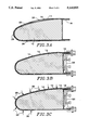
- FIG. 1 is an exploded perspective view of a forming retort for a leading edge of an airplane wing;
- FIG. 2 is a perspective view of the assembled retort of FIG. 1;
- FIGS. 3A-3E are cross sectional views of the forming retort of FIG. 2 for various phases of preparation for heat treatment and thereafter;
- FIGS. 4A and B are cross sectional views of a retort with a female form tool, before and after vacuum is applied;
- FIG. 5 is a cross sectional view of an alternate method of envelope forming using an integrally heated forming tool
- FIG. 6 is a perspective view of the present invention applied to sheet metal flattening
- FIG. 7 is a cross sectional view of an assembled retort showing the clamp of FIG. 3 in greater detail;
- FIG. 8 is a cut-away perspective view of a portion of the clamp of FIG. 7;
- FIG. 9 is a perspective view of an assembled retort with a plurality of clamps attached thereto.
- FIG. 10 is a perspective view of a clamping device for holding the envelope tight against a flattening plate during sealing.
- the part 10 which may comprise a perforated sheet of titanium suitable for the leading edge of an airplane wing, is placed against form tool 12 contoured within desired tolerance to the shape which is ultimately desired for the part 10.
- Form tool 12 is suitably constructed of steel.
- envelope skin 14, end pieces 15 and 16 and back piece 18 comprised stainless steel members having a thickness of approximately 0.032 inch, while part 10 comprised titanium sheet having a thickness of 0.040 inch.
- Stainless steel was chosen as envelope material partly because it does not react with titanium and is relatively clean, i.e., normally free of surface contaminants such as oil, which could contaminate the part.
- Envelope end 16 is provided with an opening or fitting 20 connected to vacuum/argon supply line 22 for evacuating the atmosphere within the enclosed envelope and for providing an argon atmosphere at appropriate times within the envelope as subsequently discussed herein in connection with FIGS. 3C-3E.
- Placement of the vacuum supply opening is not critical; it is simply necessary to choose a location that will not result in the vacuum hole becoming plugged during evacuation and heating.
- Tool support beams 24 are placed below the entire assembly and raise the retort to allow heat circulation underneath.
- FIG. 2 is a perspective view of the retort after the envelope has been sealed.
- the retort should be constructed to be nearly form fitting to the shape of the form tool since if the retort is not reasonably form fitting, the welded seams can crack after vacuum is applied and allow vacuum leakage.
- the envelope skin 14 is quite collapsible to adhere closely to the part and the tool.
- the entire assembly is then placed within a furnace (while maintaining the vacuum) for heat treatment to relieve residual stresses and insure the part takes on the desired shape. Performing the stress relief under a vacuum is desirable to minimize contamination of the part.
- FIG. 3 comprises cross sectional views of the envelope and part forming tool during various stages of the forming operation.
- FIG. 3A illustrates the envelope before forming pressure has been applied, but after the envelope has been sealed, and it is seen hollow areas 26 may exist at locations where the part 10 is not snug against form tool 12.
- FIG. 3B forming pressure has been applied wherein clamp assembly 28 is attached to the rear of the envelope 18 and used to force the form tool forwardly within the retort pulling envelope skin 14 more closely against the form tool. The operation of clamp assembly 28 will be discussed subsequently in connection with FIGS. 7-9. Once the clamp force has pulled the envelope skin fairly taut, vacuum pressure is provided via vacuum line 22, not illustrated in FIG.
- clamp assembly 28 can be removed (FIG. 3D) and the envelope part and tool are ready for heat treatment.
- FIG. 7 is a cross sectional view showing clamp 28 of FIG. 3 in greater detail, while FIG. 8 is a cut-away perspective view of a portion of the clamp.
- Clamp assembly 28 fits behind the retort back channel member 18 of FIGS. 1 and 3, opposite form tool 12, and includes clamp base plate 70 having threaded holes 72 for receiving pusher bolts 74.
- the clamp base is provided with four threaded holes 72 evenly spaced in the plane of the base plate so as to distribute pressure from the bolts.
- the bolts 74 threadably engage the holes, and when tightened, push against pressure plate 75 engaging channel member 18.
- Clamp base flanges 76 having their front faces attached to the base plate 70 near its perimeter at opposing edges thereof, are provided with openings 78 near the rear of each flange for receiving bolts 80.
- Clamp top members 82 joined to flanges 76 by outwardly extending spacers 84 to complete a U-shaped cross-section, are arranged to be approximately coextensive with the clamp base flanges and have holes 85 through which bolts 80 extend for receiving nuts 81.
- Each clamp top member 82 is provided with a gripper seam 86 while clamp base flanges 76 each carry a pair of spaced gripper seams 88 disposed on either side of seam 86.
- FIG. 9 is a perspective view of an assembled retort having a plurality of clamps 28 attached thereto.
- the retort is placed in a furnace for heat treatment.
- the pressure holding the part against the form tool should be released to prevent wrinkling of the part as may be caused by the differing rates of thermal expansion of the part and the form tool.
- the invention allows relatively inexpensive materials to be used as form tools, for example, carbon steel, when forming part metals such as titanium which may not have like thermal expansion rates, ASTM A-36 steel plate being used as form tool material in a particular embodiment.
- An inert gas is used because it inhibits contamination of the part; in a preferred embodiment, the retort was pressurized to approximately 10 inches H 2 O positive pressure with argon gas. Part contamination may be further reduced in the initial portion of the process by purging the retort with the inert gas for a period of time (e.g. 8 hours) before applying the vacuum and heat stress relief.
- stress relief treatment may suitably comprise heating the retort to 1,000 degrees Fahrenheit for one hour.
- FIG. 4A part 10 is placed against form tool 12 and surrounded by envelope 14, sealed as by welding at various points indicated by reference numerals 32.
- Vacuum supply line 22 is provided via orifice 20 to maintain a vacuum within the envelope whereby hollow spaces 26 are removed by external atmospheric pressure against the envelope 14 resulting in the configuration illustrated in FIG. 4B.
- FIG. 5 illustrates a cross sectional view of an alternative method of forming parts at elevated temperature.
- Part 10 is placed around form tool 12, the latter including a heater element 40, empowered by means not shown, contained within the hollow center thereof whereby the necessary heat can be supplied for the stress relief for insuring the part will take on the desired shape.
- Envelope 14 surrounds the part and tool while insulation 42 is suitably disposed in surrounding relation to the envelope. Insulation may also be included at the base of the form tool where the latter is attached to riser platform 44 by means of bolts 46.
- Platform 44 is mounted upon an envelope tightener 48 suitably comprising a hydraulically operated rod extending upwardly from a hydraulic cylinder (not shown).
- Envelope 14 is sealed against the atmosphere by means of underlying base plate 50 upon which platform 44 initially rests, an 0-ring seal 52, and a heavy "picture frame" 54 for pressing the periphery of envelope 14 tightly against base plate 50.
- Envelope 14 extends continuously from one edge of base plate 50, around the part and form tool, to the opposite edge of the base plate, and is further sealed at either end by means not shown.
- Vacuum supply 22 is connected through a passage in the base plate for evacuating the envelope during heat forming, and for supplying an inert atmosphere during the cool down period once the vacuum is released.
- the maximum range of upward motion of hydraulic tightener 48 is determined by means of shoulder bolts 56 threadably attached to base plate 50 and passing through openings in platform 44 whereby platform 44 may translate only along the length of bolts 56.
- a seal 58 is provided at the location where rod 48 passes through base plate 50, to insure maintenance of a vacuum in the part forming chamber during the foregoing procedure.
- a flattening plate 60 is provided having a vacuum hole 62 on the upper face thereof, such vacuum hole 62 being connected via an inner passage in plate 60 to vacuum line 22 through fitting 64.
- the sheet metal part 10, of smaller planar dimension than plate 60, is placed on top of the flattening plate and top sheet 14 typically of the same planar dimension as flattening plate 60 is placed over the part forming a sandwich.
- the sandwich is sealed to the atmosphere, for example by welding the top sheet to the flattening plate along the perimeter thereof.
- the envelope and sheet are suitably held against the flattening plate during welding, for example by placing weights on top of the envelope.
- a clamping device was constructed to hold the top sheet and part against the plate during welding.
- such clamping device comprises a channel member 92 extending substantially across the width of envelope sheet 14 and attached by welding at opposite ends thereof to right angle flanges 94 and 96 adapted to extend along a portion of the perimeter of the envelope in perpendicular relation to channel member 92.
- Ordinary C-clamps 98 are employed to hold the clamping device firmly against the flattening plate. Once the envelope edges are sealed, the C-clamps and clamping device can be removed.
- top sheet 14 comprised 0.032 inch thick stainless steel
- part 10 comprised 0.040 inch thick titanium
- flattening plate 60 comprised a flat steel plate one inch in thickness.
Abstract
Description
Claims (15)
Priority Applications (1)
| Application Number | Priority Date | Filing Date | Title |
|---|---|---|---|
| US07/589,058 US5144825A (en) | 1990-09-27 | 1990-09-27 | Elevated temperature envelope forming |
Applications Claiming Priority (1)
| Application Number | Priority Date | Filing Date | Title |
|---|---|---|---|
| US07/589,058 US5144825A (en) | 1990-09-27 | 1990-09-27 | Elevated temperature envelope forming |
Publications (1)
| Publication Number | Publication Date |
|---|---|
| US5144825A true US5144825A (en) | 1992-09-08 |
Family
ID=24356434
Family Applications (1)
| Application Number | Title | Priority Date | Filing Date |
|---|---|---|---|
| US07/589,058 Expired - Fee Related US5144825A (en) | 1990-09-27 | 1990-09-27 | Elevated temperature envelope forming |
Country Status (1)
| Country | Link |
|---|---|
| US (1) | US5144825A (en) |
Cited By (15)
| Publication number | Priority date | Publication date | Assignee | Title |
|---|---|---|---|---|
| US5210946A (en) * | 1992-06-26 | 1993-05-18 | Hudson Products Corporation | Leading edge protection for fan blade |
| FR2696957A1 (en) * | 1992-10-21 | 1994-04-22 | Snecma | Moulding procedure for flat titanium alloy components - placing between die and matrices and holding under pressure at ambient temperature before heating in a furnace |
| WO1994023890A1 (en) * | 1993-04-20 | 1994-10-27 | Chromalloy Gas Turbine Corporation | Hot forming process |
| EP0726106A1 (en) * | 1995-02-03 | 1996-08-14 | Daimler-Benz Aerospace Aktiengesellschaft | Method for reshaping plate-like elements |
| WO1999020431A1 (en) * | 1997-10-21 | 1999-04-29 | Allison Advanced Development Company | Airfoil for a gas turbine engine and method of manufacture |
| WO2000016925A1 (en) * | 1998-09-18 | 2000-03-30 | Rolls-Laval Heat Exchangers Limited | A method of manufacturing an article by hot forming |
| US6420051B1 (en) * | 1997-10-25 | 2002-07-16 | Gkss-Forschungszentrum Gaesthacht Gmbh | Device for encapsulating blanks of high temperature metallic alloys |
| US6598866B2 (en) * | 1999-10-29 | 2003-07-29 | Bae Systems Plc | Workpiece support |
| EP1375344A1 (en) * | 2002-06-26 | 2004-01-02 | Gamesa Desarrollos Aeronauticos, S.A. (Sociedad Unipersonal) | Winglet leading edge and its manufacturing method |
| US20070226977A1 (en) * | 2006-03-28 | 2007-10-04 | Stern Eric J | Machining technique with selective and localized placement of tooling material |
| US20100054945A1 (en) * | 2008-08-28 | 2010-03-04 | Rolls-Royce Plc. | Aerofoil |
| US9222362B2 (en) | 2010-11-05 | 2015-12-29 | Barnes Group Inc. | Hybrid metal leading edge part and method for making the same |
| US20160057812A1 (en) * | 2013-06-11 | 2016-02-25 | Canon Anelva Corporation | Vacuum processing device |
| US9757788B2 (en) | 2015-05-07 | 2017-09-12 | The Boeing Company | Method and apparatus for hot forming metal parts |
| EP3452626A4 (en) * | 2016-06-15 | 2019-11-13 | Ducommun Aerostructures, Inc. | Vacuum forming method |
Citations (16)
| Publication number | Priority date | Publication date | Assignee | Title |
|---|---|---|---|---|
| US2728317A (en) * | 1951-10-23 | 1955-12-27 | Walton S Clevenger | Apparatus for hydraulic die forming |
| US2825794A (en) * | 1955-02-23 | 1958-03-04 | Edward A Stalker | Process and apparatus for fabricating hollow blades for compressors, turbines, and the like |
| US3263319A (en) * | 1964-02-28 | 1966-08-02 | Varian Associates | Method of cold deep drawing metal foil |
| US3340101A (en) * | 1965-04-02 | 1967-09-05 | Ibm | Thermoforming of metals |
| US3566661A (en) * | 1968-07-29 | 1971-03-02 | Budd Co | Metal forming |
| US3584368A (en) * | 1968-07-10 | 1971-06-15 | Aluminum Co Of America | Titanium fabrication |
| DE2117950A1 (en) * | 1971-04-14 | 1972-10-19 | Hetsch H | Shaping metal blanks - in one operation by deep-drawing without intermediate annealing or the need for lubricant |
| US3722068A (en) * | 1971-02-22 | 1973-03-27 | Northrop Corp | Method for forming titanium sheets |
| US3974673A (en) * | 1975-04-07 | 1976-08-17 | Rockwell International Corporation | Titanium parts manufacturing |
| US3979815A (en) * | 1974-07-22 | 1976-09-14 | Nissan Motor Co., Ltd. | Method of shaping sheet metal of inferior formability |
| SU590163A1 (en) * | 1976-04-05 | 1978-01-30 | Предприятие П/Я В-8620 | Method of making sculptures from metal |
| US4081892A (en) * | 1976-11-01 | 1978-04-04 | Flow Industries, Inc. | Method of making composite structure |
| US4706361A (en) * | 1985-02-21 | 1987-11-17 | Bbc Brown, Boveri & Company, Ltd. | Process for the hot-forming of at least one sheet made of a material that is difficult to work |
| US4748837A (en) * | 1985-12-11 | 1988-06-07 | Hitachi, Ltd. | Method of forming spherical shells |
| SU1488099A1 (en) * | 1987-02-11 | 1989-06-23 | Производственное Объединение Турбостроения "Ленинградский Металлический Завод" | Method of hydraulic machine blades |
| US4984348A (en) * | 1989-01-17 | 1991-01-15 | Rohr Industries, Inc. | Superplastic drape forming |
-
1990
- 1990-09-27 US US07/589,058 patent/US5144825A/en not_active Expired - Fee Related
Patent Citations (16)
| Publication number | Priority date | Publication date | Assignee | Title |
|---|---|---|---|---|
| US2728317A (en) * | 1951-10-23 | 1955-12-27 | Walton S Clevenger | Apparatus for hydraulic die forming |
| US2825794A (en) * | 1955-02-23 | 1958-03-04 | Edward A Stalker | Process and apparatus for fabricating hollow blades for compressors, turbines, and the like |
| US3263319A (en) * | 1964-02-28 | 1966-08-02 | Varian Associates | Method of cold deep drawing metal foil |
| US3340101A (en) * | 1965-04-02 | 1967-09-05 | Ibm | Thermoforming of metals |
| US3584368A (en) * | 1968-07-10 | 1971-06-15 | Aluminum Co Of America | Titanium fabrication |
| US3566661A (en) * | 1968-07-29 | 1971-03-02 | Budd Co | Metal forming |
| US3722068A (en) * | 1971-02-22 | 1973-03-27 | Northrop Corp | Method for forming titanium sheets |
| DE2117950A1 (en) * | 1971-04-14 | 1972-10-19 | Hetsch H | Shaping metal blanks - in one operation by deep-drawing without intermediate annealing or the need for lubricant |
| US3979815A (en) * | 1974-07-22 | 1976-09-14 | Nissan Motor Co., Ltd. | Method of shaping sheet metal of inferior formability |
| US3974673A (en) * | 1975-04-07 | 1976-08-17 | Rockwell International Corporation | Titanium parts manufacturing |
| SU590163A1 (en) * | 1976-04-05 | 1978-01-30 | Предприятие П/Я В-8620 | Method of making sculptures from metal |
| US4081892A (en) * | 1976-11-01 | 1978-04-04 | Flow Industries, Inc. | Method of making composite structure |
| US4706361A (en) * | 1985-02-21 | 1987-11-17 | Bbc Brown, Boveri & Company, Ltd. | Process for the hot-forming of at least one sheet made of a material that is difficult to work |
| US4748837A (en) * | 1985-12-11 | 1988-06-07 | Hitachi, Ltd. | Method of forming spherical shells |
| SU1488099A1 (en) * | 1987-02-11 | 1989-06-23 | Производственное Объединение Турбостроения "Ленинградский Металлический Завод" | Method of hydraulic machine blades |
| US4984348A (en) * | 1989-01-17 | 1991-01-15 | Rohr Industries, Inc. | Superplastic drape forming |
Cited By (24)
| Publication number | Priority date | Publication date | Assignee | Title |
|---|---|---|---|---|
| US5210946A (en) * | 1992-06-26 | 1993-05-18 | Hudson Products Corporation | Leading edge protection for fan blade |
| FR2696957A1 (en) * | 1992-10-21 | 1994-04-22 | Snecma | Moulding procedure for flat titanium alloy components - placing between die and matrices and holding under pressure at ambient temperature before heating in a furnace |
| WO1994023890A1 (en) * | 1993-04-20 | 1994-10-27 | Chromalloy Gas Turbine Corporation | Hot forming process |
| US5694683A (en) * | 1993-04-20 | 1997-12-09 | Chromalloy Gas Turbine Corporation | Hot forming process |
| EP0726106A1 (en) * | 1995-02-03 | 1996-08-14 | Daimler-Benz Aerospace Aktiengesellschaft | Method for reshaping plate-like elements |
| US6264771B1 (en) * | 1995-02-03 | 2001-07-24 | Daimler-Benz Aerospace Ag | Process for forming a plate-like component |
| WO1999020431A1 (en) * | 1997-10-21 | 1999-04-29 | Allison Advanced Development Company | Airfoil for a gas turbine engine and method of manufacture |
| US6003754A (en) * | 1997-10-21 | 1999-12-21 | Allison Advanced Development Co. | Airfoil for a gas turbine engine and method of manufacture |
| US6003756A (en) * | 1997-10-21 | 1999-12-21 | Allison Advanced Development Company | Airfoil for gas a turbine engine and method of manufacture |
| US6420051B1 (en) * | 1997-10-25 | 2002-07-16 | Gkss-Forschungszentrum Gaesthacht Gmbh | Device for encapsulating blanks of high temperature metallic alloys |
| WO2000016925A1 (en) * | 1998-09-18 | 2000-03-30 | Rolls-Laval Heat Exchangers Limited | A method of manufacturing an article by hot forming |
| US6598866B2 (en) * | 1999-10-29 | 2003-07-29 | Bae Systems Plc | Workpiece support |
| EP1375344A1 (en) * | 2002-06-26 | 2004-01-02 | Gamesa Desarrollos Aeronauticos, S.A. (Sociedad Unipersonal) | Winglet leading edge and its manufacturing method |
| ES2242461A1 (en) * | 2002-06-26 | 2005-11-01 | Gamesa Desarrollos Aeronauticos, S.A. | Winglet leading edge and its manufacturing method |
| US20070226977A1 (en) * | 2006-03-28 | 2007-10-04 | Stern Eric J | Machining technique with selective and localized placement of tooling material |
| US7380321B2 (en) * | 2006-03-28 | 2008-06-03 | The Boeing Company | Machining technique with selective and localized placement of tooling material |
| US20100054945A1 (en) * | 2008-08-28 | 2010-03-04 | Rolls-Royce Plc. | Aerofoil |
| US8459955B2 (en) * | 2008-08-28 | 2013-06-11 | Rolls-Royce Plc | Aerofoil |
| US9222362B2 (en) | 2010-11-05 | 2015-12-29 | Barnes Group Inc. | Hybrid metal leading edge part and method for making the same |
| US20160057812A1 (en) * | 2013-06-11 | 2016-02-25 | Canon Anelva Corporation | Vacuum processing device |
| US9757788B2 (en) | 2015-05-07 | 2017-09-12 | The Boeing Company | Method and apparatus for hot forming metal parts |
| EP3452626A4 (en) * | 2016-06-15 | 2019-11-13 | Ducommun Aerostructures, Inc. | Vacuum forming method |
| EP3964596A1 (en) * | 2016-06-15 | 2022-03-09 | Ducommun Aerostructures, Inc. | Vacuum forming method |
| US11359863B2 (en) | 2016-06-15 | 2022-06-14 | Ducommun Aerostructures, Inc. | Vacuum forming method |
Similar Documents
| Publication | Publication Date | Title |
|---|---|---|
| US5144825A (en) | Elevated temperature envelope forming | |
| JP4952056B2 (en) | Preform manufacturing method and preform manufacturing apparatus | |
| US4429824A (en) | Delta-alpha bond/superplastic forming method of fabricating titanium structures and the structures resulting therefrom | |
| US4691857A (en) | Method of shaping a workpiece | |
| US5692881A (en) | Hollow metallic structure and method of manufacture | |
| JP4190034B2 (en) | Metal diffusion bonding | |
| US5226578A (en) | Method of manufacturing an article, a method of diffusion bonding and a vacuum chamber | |
| JP4422839B2 (en) | Method for producing open-type polyimide molded product | |
| JPH02139209A (en) | Device and method of laminating composite material | |
| KR100417081B1 (en) | Vacuum laminating equipment and hot lamination • | |
| JPH0615531A (en) | Method for producing article by superplastic molding and diffusion joint | |
| US6418619B1 (en) | Method of manufacturing an article by superplastic forming and diffusion bonding | |
| US5599472A (en) | Resealable retort for induction processing of organic matrix composites or metals | |
| US3011254A (en) | Double differential pressure honeycomb sandwich panel brazing | |
| KR20140069207A (en) | Methods and apparati for handling, heating and cooling a substrate upon which a pattern is made by a tool in heat flowable material coating, including substrate transport, tool laydown, tool tensioning, and tool retraction | |
| EP0367642A1 (en) | Method and device for shaping sheet metal, particularly for realizing a shadow mask for cathode ray tubes obtained according to the method | |
| GB2269556A (en) | A method of manufacturing an article by diffusion bonding | |
| US3170428A (en) | Fixture for making honeycomb panel | |
| US5484977A (en) | Method of manufacturing an article by superplastic forming and diffusion bonding and vacuum chamber for use in processing workpieces for superplastic forming and diffusion bonding | |
| US3091846A (en) | Method of brazing | |
| US5749254A (en) | Air bearing assist in pneumatic forming of thin foil materials | |
| US4197977A (en) | Method of making an actively-cooled titanium structure | |
| JP4776866B2 (en) | Method for forming structure made of aluminum alloy | |
| US20060027308A1 (en) | Method and apparatus for curing patches on composite structures having complex substrates | |
| FR2501544A1 (en) | ASSEMBLY OF MATRICES FOR THE REFACTION OF AN ARTICLE WITH AN IRREGULAR SHAPE |
Legal Events
| Date | Code | Title | Description |
|---|---|---|---|
| AS | Assignment |
Owner name: BOEING COMPANY, THE, SEATTLE, WA, A CORP. OF DE Free format text: ASSIGNMENT OF ASSIGNORS INTEREST.;ASSIGNOR:BURG, BRUCE M.;REEL/FRAME:005529/0232 Effective date: 19901107 Owner name: BOEING COMPANY, THE, SEATTLE, WA, A CORP. OF DE Free format text: ASSIGNMENT OF ASSIGNORS INTEREST.;ASSIGNOR:GANE, DAVID H.;REEL/FRAME:005529/0230 Effective date: 19901107 Owner name: BOEING COMPANY, THE, SEATTLE, WA, A CORP. OF DE Free format text: ASSIGNMENT OF ASSIGNORS INTEREST.;ASSIGNOR:STAROWSKI, ROBERT M.;REEL/FRAME:005529/0228 Effective date: 19901115 |
|
| FEPP | Fee payment procedure |
Free format text: PAYOR NUMBER ASSIGNED (ORIGINAL EVENT CODE: ASPN); ENTITY STATUS OF PATENT OWNER: LARGE ENTITY |
|
| FPAY | Fee payment |
Year of fee payment: 4 |
|
| SULP | Surcharge for late payment | ||
| FEPP | Fee payment procedure |
Free format text: PAYER NUMBER DE-ASSIGNED (ORIGINAL EVENT CODE: RMPN); ENTITY STATUS OF PATENT OWNER: LARGE ENTITY Free format text: PAYOR NUMBER ASSIGNED (ORIGINAL EVENT CODE: ASPN); ENTITY STATUS OF PATENT OWNER: LARGE ENTITY |
|
| REMI | Maintenance fee reminder mailed | ||
| LAPS | Lapse for failure to pay maintenance fees | ||
| FP | Lapsed due to failure to pay maintenance fee |
Effective date: 20000908 |
|
| STCH | Information on status: patent discontinuation |
Free format text: PATENT EXPIRED DUE TO NONPAYMENT OF MAINTENANCE FEES UNDER 37 CFR 1.362 |