US5146991A - Method for well production - Google Patents
Method for well production Download PDFInfo
- Publication number
- US5146991A US5146991A US07/684,162 US68416291A US5146991A US 5146991 A US5146991 A US 5146991A US 68416291 A US68416291 A US 68416291A US 5146991 A US5146991 A US 5146991A
- Authority
- US
- United States
- Prior art keywords
- cycle
- plunger
- state
- time
- interval
- Prior art date
- Legal status (The legal status is an assumption and is not a legal conclusion. Google has not performed a legal analysis and makes no representation as to the accuracy of the status listed.)
- Expired - Lifetime
Links
- 238000000034 method Methods 0.000 title claims abstract description 72
- 238000004519 manufacturing process Methods 0.000 title abstract description 24
- 230000004044 response Effects 0.000 claims abstract description 22
- 239000012530 fluid Substances 0.000 claims description 18
- 238000009434 installation Methods 0.000 claims description 17
- 230000001105 regulatory effect Effects 0.000 claims description 15
- 230000007704 transition Effects 0.000 claims description 15
- 229930195733 hydrocarbon Natural products 0.000 claims description 12
- 150000002430 hydrocarbons Chemical class 0.000 claims description 12
- 230000001965 increasing effect Effects 0.000 claims description 12
- 239000004215 Carbon black (E152) Substances 0.000 claims description 10
- 238000004891 communication Methods 0.000 claims description 7
- 230000003247 decreasing effect Effects 0.000 claims description 7
- 238000001514 detection method Methods 0.000 claims description 3
- 238000011156 evaluation Methods 0.000 abstract description 3
- 239000007789 gas Substances 0.000 description 25
- 239000007788 liquid Substances 0.000 description 21
- 239000003990 capacitor Substances 0.000 description 17
- 238000003825 pressing Methods 0.000 description 16
- 230000000881 depressing effect Effects 0.000 description 15
- 230000006870 function Effects 0.000 description 15
- 230000008859 change Effects 0.000 description 6
- 230000000694 effects Effects 0.000 description 6
- 238000010586 diagram Methods 0.000 description 5
- 238000012423 maintenance Methods 0.000 description 5
- 230000002093 peripheral effect Effects 0.000 description 4
- 230000000903 blocking effect Effects 0.000 description 3
- 230000001276 controlling effect Effects 0.000 description 3
- 239000013078 crystal Substances 0.000 description 3
- 230000001976 improved effect Effects 0.000 description 3
- 239000011159 matrix material Substances 0.000 description 3
- 230000008569 process Effects 0.000 description 3
- 230000002829 reductive effect Effects 0.000 description 3
- 230000000087 stabilizing effect Effects 0.000 description 3
- 230000003068 static effect Effects 0.000 description 3
- XLYOFNOQVPJJNP-UHFFFAOYSA-N water Substances O XLYOFNOQVPJJNP-UHFFFAOYSA-N 0.000 description 3
- WHXSMMKQMYFTQS-UHFFFAOYSA-N Lithium Chemical compound [Li] WHXSMMKQMYFTQS-UHFFFAOYSA-N 0.000 description 2
- 230000002159 abnormal effect Effects 0.000 description 2
- 238000013459 approach Methods 0.000 description 2
- 230000008878 coupling Effects 0.000 description 2
- 238000010168 coupling process Methods 0.000 description 2
- 238000005859 coupling reaction Methods 0.000 description 2
- 230000000994 depressogenic effect Effects 0.000 description 2
- 230000009977 dual effect Effects 0.000 description 2
- 238000005516 engineering process Methods 0.000 description 2
- 239000004973 liquid crystal related substance Substances 0.000 description 2
- 229910052744 lithium Inorganic materials 0.000 description 2
- VNWKTOKETHGBQD-UHFFFAOYSA-N methane Chemical compound C VNWKTOKETHGBQD-UHFFFAOYSA-N 0.000 description 2
- 238000012544 monitoring process Methods 0.000 description 2
- 238000011017 operating method Methods 0.000 description 2
- 230000035515 penetration Effects 0.000 description 2
- 230000008439 repair process Effects 0.000 description 2
- 238000013022 venting Methods 0.000 description 2
- 102000020086 Ephrin-A1 Human genes 0.000 description 1
- 108010043945 Ephrin-A1 Proteins 0.000 description 1
- 230000004308 accommodation Effects 0.000 description 1
- 238000004458 analytical method Methods 0.000 description 1
- 238000003491 array Methods 0.000 description 1
- 230000008901 benefit Effects 0.000 description 1
- 230000015572 biosynthetic process Effects 0.000 description 1
- 210000004899 c-terminal region Anatomy 0.000 description 1
- 238000006243 chemical reaction Methods 0.000 description 1
- 239000013256 coordination polymer Substances 0.000 description 1
- 230000001186 cumulative effect Effects 0.000 description 1
- 230000001351 cycling effect Effects 0.000 description 1
- 230000001934 delay Effects 0.000 description 1
- 238000011161 development Methods 0.000 description 1
- 230000003292 diminished effect Effects 0.000 description 1
- 230000008030 elimination Effects 0.000 description 1
- 238000003379 elimination reaction Methods 0.000 description 1
- 230000001747 exhibiting effect Effects 0.000 description 1
- 230000002349 favourable effect Effects 0.000 description 1
- 230000005669 field effect Effects 0.000 description 1
- 238000001914 filtration Methods 0.000 description 1
- 230000003116 impacting effect Effects 0.000 description 1
- 230000001939 inductive effect Effects 0.000 description 1
- 238000007689 inspection Methods 0.000 description 1
- 230000000670 limiting effect Effects 0.000 description 1
- 230000007774 longterm Effects 0.000 description 1
- 239000000463 material Substances 0.000 description 1
- 239000003595 mist Substances 0.000 description 1
- 239000000203 mixture Substances 0.000 description 1
- 238000012806 monitoring device Methods 0.000 description 1
- 239000003345 natural gas Substances 0.000 description 1
- 239000003921 oil Substances 0.000 description 1
- 239000012188 paraffin wax Substances 0.000 description 1
- 239000003208 petroleum Substances 0.000 description 1
- 238000005086 pumping Methods 0.000 description 1
- 230000009467 reduction Effects 0.000 description 1
- 239000012260 resinous material Substances 0.000 description 1
- 230000000717 retained effect Effects 0.000 description 1
- 238000012552 review Methods 0.000 description 1
- 238000010079 rubber tapping Methods 0.000 description 1
- 150000003839 salts Chemical class 0.000 description 1
- 239000004576 sand Substances 0.000 description 1
- 238000007789 sealing Methods 0.000 description 1
- 239000004065 semiconductor Substances 0.000 description 1
- 239000007787 solid Substances 0.000 description 1
- 239000007921 spray Substances 0.000 description 1
- 229920001187 thermosetting polymer Polymers 0.000 description 1
- 230000001052 transient effect Effects 0.000 description 1
- 230000001960 triggered effect Effects 0.000 description 1
- 238000009966 trimming Methods 0.000 description 1
- 238000004804 winding Methods 0.000 description 1
Images


Classifications
-
- E—FIXED CONSTRUCTIONS
- E21—EARTH DRILLING; MINING
- E21B—EARTH DRILLING, e.g. DEEP DRILLING; OBTAINING OIL, GAS, WATER, SOLUBLE OR MELTABLE MATERIALS OR A SLURRY OF MINERALS FROM WELLS
- E21B43/00—Methods or apparatus for obtaining oil, gas, water, soluble or meltable materials or a slurry of minerals from wells
- E21B43/12—Methods or apparatus for controlling the flow of the obtained fluid to or in wells
- E21B43/121—Lifting well fluids
-
- Y—GENERAL TAGGING OF NEW TECHNOLOGICAL DEVELOPMENTS; GENERAL TAGGING OF CROSS-SECTIONAL TECHNOLOGIES SPANNING OVER SEVERAL SECTIONS OF THE IPC; TECHNICAL SUBJECTS COVERED BY FORMER USPC CROSS-REFERENCE ART COLLECTIONS [XRACs] AND DIGESTS
- Y10—TECHNICAL SUBJECTS COVERED BY FORMER USPC
- Y10T—TECHNICAL SUBJECTS COVERED BY FORMER US CLASSIFICATION
- Y10T137/00—Fluid handling
- Y10T137/8158—With indicator, register, recorder, alarm or inspection means
- Y10T137/8208—Time
-
- Y—GENERAL TAGGING OF NEW TECHNOLOGICAL DEVELOPMENTS; GENERAL TAGGING OF CROSS-SECTIONAL TECHNOLOGIES SPANNING OVER SEVERAL SECTIONS OF THE IPC; TECHNICAL SUBJECTS COVERED BY FORMER USPC CROSS-REFERENCE ART COLLECTIONS [XRACs] AND DIGESTS
- Y10—TECHNICAL SUBJECTS COVERED BY FORMER USPC
- Y10T—TECHNICAL SUBJECTS COVERED BY FORMER US CLASSIFICATION
- Y10T137/00—Fluid handling
- Y10T137/8593—Systems
- Y10T137/86389—Programmer or timer
- Y10T137/86405—Repeating cycle
- Y10T137/86421—Variable
-
- Y—GENERAL TAGGING OF NEW TECHNOLOGICAL DEVELOPMENTS; GENERAL TAGGING OF CROSS-SECTIONAL TECHNOLOGIES SPANNING OVER SEVERAL SECTIONS OF THE IPC; TECHNICAL SUBJECTS COVERED BY FORMER USPC CROSS-REFERENCE ART COLLECTIONS [XRACs] AND DIGESTS
- Y10—TECHNICAL SUBJECTS COVERED BY FORMER USPC
- Y10T—TECHNICAL SUBJECTS COVERED BY FORMER US CLASSIFICATION
- Y10T137/00—Fluid handling
- Y10T137/8593—Systems
- Y10T137/86389—Programmer or timer
- Y10T137/86445—Plural, sequential, valve actuations
- Y10T137/86461—Variable cycle
Definitions
- plunger lift is classified as a separate and distinct method of artificial lift, although in some instances, it serves as only a temporary means of keeping a well commercially feasible prior to the installation of another method of artificial lift.
- the controller is designed to respond to system parameters to override the cycle timing to accommodate conditions where such timing should be overridden and subsequently re-initiated on an automatic basis.
- Sold under the trademark "Digitrol” the controller has been seen to have had a profound impact upon well production.
- Liquilift The initial version of the Liquilift device is described in U.S. Pat. No. 4,352,376, by Norwood, entitled “Controller for Well Installations", issued Oct. 5, 1982.
- the present invention is addressed to a method for operating a well installation employing plunger lift procedures.
- a continuous monitoring and adjustment of well performance is carried out through an evaluation of plunger speed.
- the speed at which the plunger travels from the bottom of the tubing string of the well to the wellhead is evaluated by each cycle. Based upon that evaluation, changes may be made to the off-cycle time and afterflow cycle time to tune the well toward a performance which is optimized at a consistent plunger speed considered to achieve maximized production.
- the well technician To achieve plunger speed-based control, the well technician, relying on experience and judgement, selects a consistent on-cycle interval and, within that interval, windows are then set to reflect fast, good, and slow speeds for the plunger to arrive at the wellhead. These windows are developed by electing low-time and high-time settings and loading them into the controller. Instead of the technician forcing the well to perform to pre-conceived operating times and pressures, the technician only is required to change the operating windows to be more or less aggressive.
- the production method will make no change to operating times if the plunger continues to surface at a good plunger speed as evidenced by arriving within a good window. However, the production technique will decrease the off-cycle time and increase the afterflow time should the plunger surface within a fast window.
- the approach will increase the off-time interval and decrease the afterflow time should the plunger surface within a slow window.
- the technique seeks to avoid failure of the plunger to surface during an on-time. However, should such a failure occur, additional off-time is added to allow for pressure build-up.
- the production technique further is capable of performing in conjunction with two motor valves, one operating as a sales valve and the other as a tank valve or valve to a lower pressure sales line.
- the latter motor valve can be operated to allow for emergency venting should abnormal operating conditions exist.
- Override capability is made possible where sales line pressures may exceed normal operating conditions and a shut-in capability is programmable where consecutive failures of plunger arrival or slow plunger runs are encountered.
- Complete program control of time adjustments and others can be altered or manipulated in the field by the well operator both to maximize well production through consistent plunger speed performance, and for the purpose of maintenance convenience, for example, providing cycle termination but control parameter maintenance where the plunger is to be recovered for maintenance or the like.
- Another feature of the invention provides a method for operating a well installation having a control valve regulating the flow of fluid hydrocarbon from a well tubing string to a sales line is selectively actuated between an on-state and an off-state, and wherein a plunger is located within the tubing string of the well for movement between a lower region and a wellhead sensing position which comprises the steps of:
- Another feature of the invention provides a method for operating a well installation having a sales control valve regulating the flow of fluid hydrocarbon from a well tubing string to a sales line is selectively actuated to establish an on-state and an off-state, wherein a tank is provided for receiving fluid, and wherein a plunger is located within the tubing string for movement between a lower region and a wellhead sensing position, comprising the steps of:
- tank control valve coupled for regulating the flow of fluid hydrocarbon from the well tubing string to the tank, the tank control valve being actuable to establish a tank on-state and further actuable to close fluid flow communication between the tubing string and the tank;
- Another feature of the invention provides a method for operating a well installation having a control valve regulating the flow of hydrocarbon from a well tubing string to a sales line is selectively actuated between an on-cycle and an off-cycle, and wherein a plunger is located within the tubing string of the well for movement between a lower region and a wellhead sensing position, comprising the steps of:
- Another feature of the invention provides a method for operating a well installation having a sales control valve regulating the flow of hydrocarbon from a well tubing string to a sales line is selectively actuated between open and closed orientations for respectively deriving an on-cycle and an off-cycle, wherein a plunger is located within the tubing string for movement between a lower region and a wellhead sensing position, and wherein a switching gauge is operatively associated with the sales line to derive a high line signal when pressure within the sales line reaches a predetermined threshold level, comprising the steps of:
- the invention accordingly, comprises the method possessing the steps which are exemplified in the following detailed disclosure.
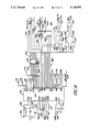
- FIG. 1 is a schematic representation of a well installation for plunger lift production according to the method of the invention
- FIG. 2 is a front view of a controller which may be employed with the method of the invention
- FIGS. 3A and 3B combine to form a flow chart describing an on-cycle control method according to the invention
- FIG. 4 is a flow chart component depicting shut-in default responses
- FIG. 5 is a flow chart showing an off-cycle component of the operating method of the invention.
- FIG. 6 is a flow chart depicting an afterflow delay cycle employed with the method of the invention.
- FIG. 7 is a flow chart showing a tank cycle employed with the well operating method of the invention.
- FIG. 8 is a flow chart showing a high line delay feature of the method of the invention.
- FIG. 9 is an enlarged view of a keypad employed with the controller of FIG. 2;
- FIG. 10 is a schematic diagram of a control circuit used with the controller employed with the invention showing microcontroller and decoder features;
- FIG. 11 is an electrical schematic diagram showing memory and calendar components of the circuit of the controller employed with the invention.
- FIG. 12 is an electrical schematic diagram of the circuit of the controller used with the invention showing power supply and reset features
- FIG. 13 is an electrical schematic diagram of a circuit employed with a controller utilized with the invention showing display components
- FIG. 14 is an electrical schematic diagram of a circuit employed with a controller used with the invention showing peripheral interface functions.
- the control technique described herein is one taking advantage of the improved microprocessor driven controller instrument being utilized by the oil industry. It combines that flexibility with plunger lift based production to achieve a maximized well output of saleable hydrocarbons and recognizes that the production signature of any given well facility will vary continuously. However, the technique further is predicated upon an essentially continuous tuning of the well to achieve plunger lifting performance at a consistent velocity or speed throughout well production. Achieving that consistency of speed is developed initially by the oil technician based upon field experience with the well at hand. For the technique to perform, efficient gas pressure and volume must be present to achieve this consistent plunger velocity. Many theories have been developed for determining the most favorable method of operation of plunger lift equipment. Through extensive field experience, operators have identified or localized limitations of such equipment. However, there are certain basic variables that always will affect overall system performance. These variables may be identified as follows:
- GLR Gas/liquid ratio
- Liquid slug pressure (water/oil ratio).
- the complexity of achieving and maintaining optimized well performance has been of such a level that the oil and gas industry has accepted substandard operation from plunger-based artificial lift systems.
- optimized performance would require a 24 hour a day visitation on the part of the technician at the well site.
- the present method utilizes the initial experience of the well operator to establish an ideal plunger rate of movement and then continuously controls, based upon variations of plunger speed to maintain that consistency of plunger operation.
- Installation 10 includes an elongate casing 12 which extends through the terrestrial surface into a gas-oil formation which serves as a pressurized reservoir for oil, gas, water and the like. Surface control over the well is maintained by a well head represented generally at 14.
- Wellhead 14 incorporates apropriate hangers and seals which serve to support a tubing string 16 which extends from the well head 14 to an open lower end 18 situate in the vicinity of the lower level or region of casing 12.
- Installed above the opening 18 is a bumper structure 20 which functions to stop and limit the travel of a piston-like plunger 22.
- Plunger 22 is seen adjacent the flange coupling 24 serving to associate the lower well components with wellhead 14.
- a master valve 26 Above flange 24 is a master valve 26 and immediately thereabove a T-connection 28.
- Wellhead 14 then includes a tube connector portion 30 which extends to another T-connection 32, the top of which is seen to be coupled with a lubricator 34.
- the lubricator component 34 is threadably engaged with T-connector 32 and is removable by unscrewing it utilizing handles as at 36.
- a catcher 38 Within tube portion 30 there is provided a catcher 38 having a handle 40 which may be manipulated by the well operator to position or arm a plunger dog within the tube portion 30 so as to catch the plunger 22 as it ascends to the lubricator 34.
- the plunger 22 then can be accessed for maintenance, for example, by removing lubricator 34.
- T-connection 28 is seen to provide fluid communication between the tubing string 16 and a conduit represented at piping 42 which extends, in turn, as represented by arrow 44 to a separator represented at 46.
- Control over the conduit 42 is by a motor valve 48 which, because of its function in the instant system is designated as a "sales valve".
- the valve 48 is controlled to open and close conduit 42 by a microprocessor driven controller 50, such control being represented by line 52.
- the controller 50 may be fashioned similar to that described in Norwood, U.S. Pat. No. 4,352,376, issued Oct. 5, 1982, entitled “Controller for Well Installations", and assigned in common herewith, which is incorporated herein by reference.
- the controller 50 will be provided as a controller marketed under the trademark "Liquilift Autocycle" wellhead controller marketed by Ferguson-Beauregard, Logic Controls, of Tyler, Tex.
- separator 46 Upon the opening of sales valve 48, an initial surge of gas followed by fluid passes through the conduit 42 to the separator 46.
- Separators as at 46 are provided in a variety of configurations, that illustrated being schematically representative of a single tube horizontal device.
- the gas and liquid mixture enters separator 46 from conduit 42, whereupon its velocity and directional flow are altered to permit fall-out of heavier liquids to the bottom of the tank as represented at 56.
- Gas and spray are collected in the upper portions of the separator 46 wherein smaller droplets coalesce to larger ones to join the fluid at 56 and, following final fluid particulate removal, as through mist extractors and the like, gas enters an outlet conduit represented by arrow 58 for entry into a gas sales outlet or sales line.
- the relatively higher pressure of the sales line as represented at 58 is monitored by a sales line gauge 60.
- Gauge 60 is of a type having a selectable sales line pressure threshold, the level of which is determined by the operator. Where the pressure in the sales gathering system is too high, and the threshold is reached or exceeded, a "high line contact" is generated as an electrical signal and conveyed as represented by line 62 to the controller 50.
- line 62 a selectable sales line pressure threshold
- a conduit 70 upon which is mounted a second motor valve 72 which functions as a tank valve or tank control valve.
- Tank valve 72 is controlled between on and off states by controller 50 as represented by line 74.
- controller 50 This control provides for the opening of tubing string 16 to the low, essentially atmospheric pressure of a tank or reservoir depicted at 76.
- the flow path for conduit 70 is represented in this regard by arrows 77 and 78. It may be observed that tank 76 retains a collection of liquids 80 which generally will be a combination of salt water and crude petroleum collected, for the most part, from the separator 56 via flow path 78 under the control of a valve as represented at 82.
- tank 76 The liquids 80 collected at tank 76 conventionally are removed by tank truck or the like by accessing the material from a lower disposed valve as at 84.
- conduit 70 may be directed to a sales gathering system of low pressure to achieve an equivalent result.
- tank or "tank valve” or “tank cycle” as used herein is intended to apply to such other arrangements.
- a plunger detector 86 located above catcher 38.
- the detector 86 provides a magnetic shut-off on arrival signal (MSO) or plunger arrival signal to the controller 50 as represented by line 88.
- MSO magnetic shut-off on arrival signal
- Additional monitoring devices for example a tubing pressure gauge casing pressure gauge, and may be provided, however, they are not required for the technique of control at hand.
- An exemplary casing pressure gauge 64 is shown having an input line 66 directed to controller 50.
- Controller 50 is contained within a highly secure water-tight housing, inasmuch as the environment within which it is called upon to perform often will be quite severe.
- This housing is, for the most part, configured as described in U.S. Pat. No. 4,532,952 by Norwood, issued Aug. 6, 1985, and assigned in common herewith.
- the housing is formed having a principal housing component 100, the forward portion of which is seen in FIG. 2 to support a circuit housing or module 102.
- Module 102 is retained in place, for example, by screws as at 104, located at the corners thereof and, in addition to carrying the circuitry of the controller, also functions to enclose an internal cavity within the principal component 100.
- a hinged front cover is shown at 106 which hingeably closes over the front or operational surface of the module 102 in water-tight secure fashion against housing component 100.
- the water-tight integrity of the arrangement is assured through the use of an O-ring seal 108 positioned within a corresponding groove within the inward surface of the front cover 106.
- Both the housing component 100 and the cover 106 preferably are formed of an impact resistant fiber-reinforced thermosetting resinous material and closure of the cover 106 may be maintained by an over-center latching device (not shown).
- the face of module 102 is shown to include a liquid crystal display (LCD) 110 which will display a variety of data including on-cycle time, off-cycle time, and various parameters employed with the instant controlling technique.
- LCD liquid crystal display
- control technique of the invention is one based upon plunger speed and seeks to operate the well such that the plunger performs consistently at an optimum value of speed which initially is determined by the well operator at the time of set-up.
- the operator will select an on-cycle time for the operation of the sales valve 48 and that value is constant, never being decremented or incremented.
- windows are established representing time element values corresponding with fast plunger rate, a slow plunger rate, and a normal plunger rate. These rates lie within the constant on-time selection of the operator.
- shut-in capability is programmable where consecutive no-arrival runs or slow runs are encountered. A complete control over the operational program can be made by operator access to the keypad 112 at the location of the well.
- Counter A This counter counts how many occurrences the plunger has run at a rate representing a good window.
- Counter B This counter will count the number of occurrences in which the plunger has run at a rate representing a fast window.
- Counter C This counter will count how many occurrences the plunger has run at a rate representing a slow window.
- Counter D This counter will count the number of occasions in which the plunger has not arrived at the well head within the on-time interval.
- Delay 1 This delay, having the typical time, for example of 5 minutes, is invoked in the event that the sales line pressure experiences an excursion causing contacts of switch gauge 60 to close to develop a high line contact signal.
- Delay 2 This delay is selected as one component of afterflow time which represents an extension of on-time occasioned with improving well performance.
- the control program also adjusts the operating parameters of the well through the use of factors which, in effect, are multiplying coefficients.
- the factors described are as follows:
- Factor 1 This factor is utilized in establishing a decrement value for adjusting afterflow interval.
- Factor 2 This factor is utilized in developing an interval of time for increasing the off-time provided by the sales valve 48.
- Factor 3 This factor is utilized in increasing the off-cycle time in conjuction with operation of the system during a tank cycle employing tank valve 72.
- Factor 4 This factor is utilized during the tank cycle for the purpose of decreasing afterflow time.
- Step 1 This step is a time increment employed to carry out a gradual decrease of the off-cycle time interval.
- Step 2 This step is a time increment employed for the purpose of increasing the interval of afterflow.
- FIGS. 3A and 3B combine to illustrate the on-cycle or on-state of the instant process, the two figures being associated by a node 7.
- the on-cycle program is seen to commence with node 1 and line 120 leading to decision block 122.
- the program determines whether an MSO contact or plunger arrival signal has been received as developed by plunger detector 86.
- plunger 22 will be at the well head and the program continues as represented at line 124 and node 5A.
- Node 5A reappears in FIG. 4.
- program continuance as represented at line 126 and block 128. Block 128 indicates that the well is shut-in and that a plunger error 1 (EPL1) is present.
- EPL1 plunger error 1
- Block 128 also indicates that present conditions are maintained. In this regard, the parameters as then exist for controlling the well are maintained for a subsequent visit to the well location by the operator, correcting the plunger condition and restarting the well essentially where it left off.
- the timer of the software is set to the on-time and the sales valve (SV) 48 is opened. This on-time is determined by the operator during on-location analysis and remains constant during the controlling cycles.
- the program then continues as represented at line 134 and block 136 to determine whether the timer has decremented to zero. In the event that it has not and the on-cycle is continuing, then as represented at line 138 and block 140, a determination is made as to whether a plunger arrival (MSO) signal has been received.
- MSO plunger arrival
- the program commences to determine the rate of travel or speed of the plunger approaching well head 14.
- the "low-time" will be determined by the operator in conjunction with selection of on-cycle or state time. For example, if an on-cycle time were selected as 20 minutes, then, the value for low time might be 7 minutes and a fast arrival of the plunger would be within a window or interval ranging in values from 0 to 7 minutes.
- counters C and D are reset to their initial values, it being recalled that counter C is a count limit for the number of times the plunger arrives in a slow window and counter D counting non-arrivals.
- the slow window may be selected with respect to a high time of 14 minutes to provide a window of values ranging from 14 minutes to 20 minutes.
- counters C and D are reset to their maximum values.
- the off-time or off-cycle interval is decremented or reduced in extent by one step 1. As noted above, step 1 will be an increment of time selected by the operator, for example 5 minutes.
- the program continues then as represented at line 184 and block 186 to determine whether the timer has decremented to a zero value, where it has not, then as represented at line 188, and block 190, the timing is carried out with a decrementing of the off-counter. Additionally, the display 110 is updated with remaining off-cycle time each minute.
- the loop then continues as represented at line 192 and decision block 194, wherein a determination is made as to whether a DELAY1 flag has been set.
- This DELAY1 is provided as a predetermined interval, for example 5 minutes, and is utilized to accommodate for high pressure transients which may occur in the sales line gathering system and which will be detected by instrument 60.
- Instrument 60 will experience a contact make in the presence of such a high sales line or gathering system pressure and will experience a contact break at such time as that pressure diminishes to acceptable values.
- the DELAY1 flag is not set, then as represented at line 196, the timing loop continues as at line 184.
- the inquiry at block 186 determines that the off-cycle timing has decremented to zero, then as represented at line 198 and node 1, the control program returns to corresponding node 1 of FIG. 3A and line 120.
- step 2 will be a time increment selected by the operator and the instructions thus serve to increment the afterflow time by that interval.
- the program then continues as represented at line 214 to the instructions at block 216 wherein the timer is then set to the DELAY2 interval and DELAY2 is commenced.
- the normal on-cycle time for sales valve 48 is extended for this revised interval of afterflow delay or DELAY2.
- Timing is represented in the chart as commencing with line 218 and block 220, providing for the decrementing of the timer and, as represented at line 222 and block 224, a determination is made as to whether the timer has decremented to zero. In the event that it has not, then looping continues as represented at line at line 226. Line 226 extends to branch block 228 wherein a determination is made as to whether the earlier-discussed DELAY1 flag has been set. This DELAY1 will be seen to represent an increment of time selected to accommodate for excessively high pressure gathering system or sales line conditions. Where this DELAY1 has not been set, then as represented at line 230, timer looping continues to line 218.
- the control program proceeds to the off-cycle sequence of events as described in conjunction with FIG. 5. For this sequence, the valve closed in connection with block 182 will be sales valve 48.
- the plunger rate of movement will correspond with a good window of time.
- the present control conditions are maintained for this good window and counters C and D are reset to their initial values in view of the appropriate arrival of the plunger.
- counter A representing the number of occurrences of the arrival of plunger 22 at the wellhead 14 within this good window of time is decremented by 1.
- the program then continues as represented at line 250 and block 252 wherein a determination is made as to whether, following the decrementation instruction at block 248, the counter A is now at zero. In the event it is not at that zero value, then as represented by line 254 and node 2, the off-cycle is commenced as described in conjunction with FIG.
- counter B representing the fast window counter
- the program diverts to the delay to or afterflow cycle.
- node 4A reappears in conjunction with line 262 leading to line 214.
- the plunger 22 arrives at wellhead 14 within the slow window of time, for example, between 14 and 20 minutes for the exemplary times given above, then the plunger time will not be less than the operator selected high time but will have arrived within the on time and, as represented at line 264 and block 266, a slow arrival will have been determined.
- the program then continues as represented at line 268 and block 270, where the DELAY2 or afterflow interval of time is reduced or decremented by a factor 1 times step 2. That factor and step are selected by the operator as part of the overall program. However, the amount of afterflow is decreased in view of this slow arrival.
- the program then continues as represented by line 272 and block 274 providing instructions for increasing the off-cycle time by a factor 2 times step 1.
- a timing loop associated with inquiry blocks 136 and 140 is shown to include line 278 representing a negative determination as to plunger arrival at block 140, as well as the decrementing to zero of timer 136. Accordingly, where the timer has not decremented to zero and the plunger has not arrived, the path represented by line 278 is seen to extend to the instructions at block 280 providing for the decrementing of the timer.
- the timing loop then continues as represented at line 282 to the inquiry at block 284 where, as before, a determination is made as to whether the DELAY1 flag has been set. This delay, as before, is predicated upon the presence of a high line signal as developed at instrument 60. Where the delay flag is not set, then as represented at line 286, the timing loop continues.
- node 3 is seen to commence a tank cycle under a well facility structuring wherein tank valve 72 generally is present.
- corrective procedures also are undertaken where the installation does not include that valve.
- line 300 is seen extending from node 3 to the inquiry presented at block 302. That inquiry determines whether or not tank valve 72 is present by a determination as to whether the tank flag or "tank on" is zero. Where that is the case, then as represented by line 304 and block 306, the DELAY2 or afterflow interval is decremented by an operator selected factor 1 multiplied by a time increment such as step 2. For example, step 2 may have a value of 5 minutes and factor 1 may have a value of 2.
- an afterflow for example, of one hour would be reduced by 10 minutes.
- the program then progresses as represented at line 308 and block 310 wherein the off-cycle time is increased by another factor 3 multiplied by a step 1.
- the off-time would be expanded by 60 minutes.
- counter D representing a predetermined count for no arrival condition is decremented by 1 and as represented at line 312 and node 2, the control program proceeds to an off-cycle routine as described earlier in conjunction with FIG. 5. Looking momentarily to that figure, it may be seen that the inquiry at block 178 determines whether or not counter C has decremented to zero or counter D has decremented to zero.
- the tank cycle proceeds as represented by line 320 and block 322 wherein the tank operator selected tank on-time is loaded. Then, as represented at line 324 and block 326, the timer is set to equal the tank-on-timer and the tank valve 72 is opened. The program then proceeds as represented at line 328 and block 330 wherein an inquiry is made as to whether the tank timer is at zero. If it is not, then as represented by line 332 and block 334, a determination is made as to whether the plunger 22 has reached wellhead 14, albeit following the time-out of the on-cycle.
- the control proceeds to an off-cycle as described in conjunction with FIG. 5.
- the DELAY2 is not equal to zero, then some afterflow interval has remained in effect, and as represented at line 364 and block 366, the DELAY2 is decremented by a factor 4 multiplied by a step 2 which reduces it to an extent desired by the operator during the programming of the controller 50.
- the afterflow or DELAY2 interval is set equal to zero and the off-time is incremented by a factor 3 multiplied by a step 1 which may be of significant total value in terms of time.
- the program then proceeds as represented at line 372 and block 374 to increment counter D representing a no arrival and, as represented at lines 376, 326, and node 2, the tank cycle exits to undertake an off-cycle as described in conjunction with FIG. 5.
- Instructions provided at block 90 look to the loading of the DELAY1 time which, for example, may be five minutes.
- a DELAY1 counter then may be incremented and the DELAY1 timer may be started. In general, this DELAY1 time value will be selected to accommodate a higher pressure surge which may occur with the opening of sales valve 48. The additional increment of time maintaining an open condition will permit a transient pressure condition to bleed down or diminish below the threshold, for example of instrument 60.
- the routine then progresses as represented at line 392 and block 394 to determine whether the DELAY1 timer has decremented to zero. In the event that it has not, then the program proceeds as represented at line 396 and block 398 to determine whether a contact break has been witnessed at instrument 60. This will mean that the pressure within the line has diminished. In the event of a negative determination at block 398, then as represented at line 400 and block 402, the DELAY1 timer is decremented and the timing procedure loops as represented by line 404.
- the keypad 112 is revealed at an enhanced level of detail.
- This keypad has the same general structuring and number of keys as the earlier-described Liquilift controller products.
- the keypad 112 has been customized to the control program described above.
- the on and off buttons which, respectively, are labeled E and F carry out the conventional function of providing a manual override to the operator at the location of the well. For example, by pressing the on button, the well will immediately undertake and on-cycle or state and, conversely, pressing the off button will cause the well to immediately assume an off-cycle or state.
- the controller 50 generally the nominal on-time for the well will be set by the operator, for example, at 30 minutes.
- the plunger arrival windows then are set by the operator based upon judgment of well performance. For example, if a fast arrival would be within the first 12 minutes of the on-time, then the operator presses the D button, followed by depressing the load time or zero button; the loading of 12 minutes, and the pressing of the D button to enter that amount. Next, a high time is selected by the operator, for example such as 20 minutes, within a 30 minute on-time. To enter the high-time, the D button is pressed, followed by the pressing of button number 1 and the loading of a 20-minute value with the numbered buttons. That value then is entered by depressing the C or D buttons or keys.
- the initial value off-time elected by the operator is selected by depressing button or key D following which button or key number 7 is depressed to display the then-present off-time.
- a value then may be entered by the operator using the numbered keys and entry is provided by depressing key or button C or D. Should the plunger 22 run within the noted good window of time, then the off-time in general will not change.
- the minimum off-time is accessed by depressing key D then key number 8 to display the current value.
- the minimum off-time is based upon knowledge of the time required for the plunger 22 to fall back to the bottom or lower region of the well. Accordingly, the program will not diminish off-time below that minimum value. The decrementing of off-time in the presence of fast arrivals will discontinue when the minimum off-time is reached.
- buttons 2 and 3 The decrementing and incrementing of time components as described in conjunction with FIGS. 3A, 3B, 6, and 7 is carried out in conjunction with buttons 2 and 3.
- values can then be loaded using the numerical key designations. Entry is by depressing either key C or D.
- steps in general operate with factors which are pre-programmed but can be changed or accessed by the operator.
- Factors 1-4 are accessed by the respective second row buttons 4-7. Should the operator desire to change or review those factors, button C is depressed followed by the depression of button D and an appropriate one of keys 4-7. Thus, a factor is multiplied by a step to develop an incrementing time.
- step 1 be assigned a 5 minute increment, and factor 3 a value of 24, then two hours, would be added to the off-time for a plunger no arrival condition in the tank cycle block 310 at FIG. 7.
- the program maintains a cumulative total of the number of cycles carried out, the number of tank cycles, the number of plunger arrivals, the total tank on-time, the total on-time, the total off-time, the number of high sales line occurrences or counts, and the time elapsed since the last clearing of the system.
- This latter clearing is carried out with respect to button number 4.
- button C By pressing button C then button number 4, the totals can be cleared.
- button C By pressing button C then button 0, the number of cycles since the last clearing are displayed.
- buttons C and C By pressing button C then button 1, the number of tank cycles occurring since the last clearing are displayed. By pressing button C, then button 2, the total elapsed time since the last clearing is displayed. By pressing button C, then button 3, the length of time required for the last plunger run is displayed. By pressing button C followed by the depressing of button 5, the total tank time is displayed. Note that there is no tank off-time, inasmuch as it is not part of the control scheme. The total on-time is accessed by pressing button C followed by the depression of button 6 and the total off-time, similarly, is accessed by pressing button C followed by the depression of button 7.
- buttons C and B By depressing button C followed by the depression of button A, the number of high line counts or pressure excursions witnessed by instrument 60 since the last clearance is displayed and by depressing button C followed by the depression of button B, the corresponding number of plunger arrivals or counts since the last general clearance are displayed. Because the software control may be altered, the version existing at a particular controller is displayed by depressing button C followed by the depression of button number 8.
- DELAY1 and DELAY2 value s may be inserted by the operator by depressing button D, then respective buttons A or D.
- the controller will display the current delay values which may be altered by pressing the numerical keys. Following the loading of any altered values, the new delay values are entered by depressing button C.
- a catch mode is provided for the convenience of operators in field. Often, the operator will wish to examine or maintenance the plunger and must time an arrival at the well location so as to be there at the appropriate point in time during an on cycle. This can be a highly inconvenient situation. Additionally, should the catcher entrap the plunger and for some reason the operator is unable then to reattend the well, considerable difficulties might ensue without an accommodation.
- the catch mode is entered by depressing button D, then button 9 and the program will respond to the next plunger arrival as occurring under catch conditions and will protect the well.
- FIG. 10 the microcontroller-based components of the newer circuit are represented.
- an 8-bit microcontroller unit (MCU) is represented at 460.
- Device 460 may be provided, for example, as a type MC68HC11 marketed by Motorola, Inc.
- the device is a high density CMOS microcontroller containing on-chip peripheral capabilities including an 8-channel, 8-bit A/D converter, static random access memory (RAM), interfacing features, and real time interrupt logic.
- the device performs in conjunction with a crystal-driven oscillator circuit 462 applying a 4 MHz crystal in conjunction with two stabilizing capacitors C1 and C2 and an impedance matching resistor R1.
- the resultant input to the corresponding EXTAL and XTAL terminals of device 460 are provided at lines 464 and 466.
- a non-maskable reset input to MCU 460 is provided to its RESET terminal from line 464 which, additionally, includes a pull-up resistor R3 coupled to voltage source VDD.
- the pull-up resistor is included inasmuch as the corresponding terminal of MCU 460 is of an open drain variety.
- the reset signal can emanate from a number of locations, including a power-up reset as described in conjunction with FIG. 13, external switches and the like.
- a maskable interrupt or interrupt request line (IRQ) 466 is coupled with pull-up resistor R5 coupled to VDD for the noted open drain input requirements of device 460.
- a similar pull-up resistor as at R4 is provided at the unused XIRQ terminal, while pull-up resistor R6, and R7 are directed to respective terminals, MODA and MODB of MCU 460 to set it to rn in an expanded mode.
- a +5 v power supply (VDD) is directed to one analog-to-digital converter terminal VRH of MCU 460 via line 468. This source is provided in conjunction with a low pass filter comprised of resistor R8 and capacitor C3.
- Line 470 connected with capacitor C3 also is directed to the reference input VRL for this A/D function.
- Resistors R9-R12 additionally are pull-up resistors coupled with unused address or capture ports within the PA0-PA7 grouping of device 460 and are required in view of the open drain configuration of those inputs.
- DATA0-DATA7 a multiplexed addressed data bus
- ports A3, R/W and E of MCU 460 are coupled, respectively, with lines 474-476 providing, in turn, respective address strobe (AS) and read/write (R/W) and enable (E) outputs.
- Bus leads DATA0-DATA7 of bus 472 additionally are directed to the 1D-8D inputs of an 8-bit latch 478.
- the clock input to latch 478 is asserted from lines 480 and 474 and the enable port thereof is coupled to ground.
- the 1Q-8Q outputs of the latch are presented at lead array 482 of a 16-bit address bus 484.
- Array 482 includes the lower address lines ADD0-ADD7, the upper address lines ADD8-ADD15 being represented by lead array 486 and coupled to the corresponding A8-A15 ports of MCU 460.
- the address data are first written to the lower address line following which an address strobe is asserted.
- the non-multiplexed address leads ADD8-ADD15 are represented at array 486 extending to bus 484.
- a three line grouping of this array 486 is directed to the A,B, and C terminals of a 3-to-8 decoder 488 via three-line lead array 490.
- Device 488 which may be provided, for example as a type 74HC138, functions as part of a decoding network represented generally at 492.
- the G1 input to decoder 488 receives the enable (E) signal from MCU 460 via line 494, while the G2A and G2B terminals simultaneously receive an input via line 496 which, in turn, extends to line 498 which is the output of an AND gate 500, the inputs to which are provided from dual leads 502 of address bus 484.
- Selected outputs from decoder 488 are a RAM enable (RAM EN) at line 504 and enable output (EN2) at line 506 and another enable output (EN4) at line 508.
- RAM EN RAM enable
- EN2 enable output
- EN4 another enable output
- line 498 extends to one input of a NAND gate 510, the opposite input to which is developed from lines 512 and 514, the latter extending to enable (E) line 475.
- the low true or active output of gate 510 at line 516 provides a read only memory enable low true signal (ROM EN).
- Gates 500 and 510 as so connected, function to isolate decoder 488 by virtue of the signal asserted from line 498 and 496 during such time as an enable signal is presented at line 516.
- an AND gate 518 which is coupled to two leads 520 from bus 484 and NAND gate 522, the inputs to which are coupled to one lead 524 of bus 484.
- the respective outputs of gates 518 and 522 at lines 526 and 528 are directed to two inputs of three input AND gate 530.
- a third input to gate 530 is from line 514 carrying the enable (E) signal.
- the output of gate 530 which is active high, is utilized to provide an enable signal (EN3) directed, in turn, to the display 110.
- an enable signal (EN3) directed, in turn, to the display 110.
- the address bus 484 is seen to reappear having leads ADD0-ADD13 at lead array 536 directed to the corresponding A0-A13 address input ports of a 16K ⁇ 8 UV erasable and electrically reprogrammable CMOS read only memory (EPROM) 538.
- EPROM CMOS read only memory
- the output of EPROM 538 at its DQ0-DQ7 ports is directed to 8-lead databus 472 through lead array 540.
- VDD power supply is provided to EPROM 538 from line 542, while an enable signal (ROM EN) is utilized to select the component via line 516 as described earlier in conjunction with FIG. 10.
- Device 538 may be provided, for example, as a type NMC27C128B marketed by National Semiconductor, Inc.
- Leads ADD0-ADD12 of 16 lead address bus 484 are directed via lead array 544 to the corresponding A0-A12 input ports of an 8K ⁇ 8 LSI static random access memory (RAM) 546, the input/output ports I/01-I/08 ports of which are coupled via lead array 548 to data bus 472.
- the chip select (CS1) port of device 546 is enabled from the enable signal developed at line 504 as described in conjunction with FIG. 10, while the WE port thereof receives an R/W signal from earlier-described line 576.
- VDD power is supplied to the CS2 terminal thereof via line 550.
- a resistor R21 coupled to ground additionally is seen coupled to line 550 for the purpose of maintaining port CS2 at a lower level in the event of battery loss or the like.
- Device 546 may be provided as a type CDN6264 LSI static RAM marketed by RCA.
- Databus 472 also is seen directed via lead array 552 to the AD0-AD7 input address ports of a real-time clock 554.
- a real-time clock 554 Provided, for example, as a type 6818 A real time clock (RTC) marketed by Motorola Corporation, device 554 derives its time base from an oscillator network 556 including a 32 KHz crystal performing in conjunction with stabilizing capacitors C4 and C5. Resistors R22 and R23 of the network provide for impedance matching and the network is seen to be coupled with RTC 554 via lines 558 and 560.
- RTC real time clock
- the address strobe (AS) input thereto is seen coupled to line 474; the R/W input thereto is seen coupled with line 476; the enable (E) input thereto is seen coupled with line 475 and the chip select (CS) is seen coupled to enable line 506, those input lines being derived from MCU 460 as described in conjunction with FIG. 10. Additionally, a reset input is provided via line 562.
- Device 554 provides an interrupt request as earlier-described in connection with FIG. 10 via line 466 and its power supply input including voltage back-up from a lithium battery is seen developed from line 564 which is directed to the MOT terminal thereof.
- Line 564 also is seen coupled to the CSFS terminal of device 554 via line 566 and to an RC network 568, the delay output of which extends via line 570 to the power sense (PSN) terminal of the RTC device 554.
- PSN power sense
- the controller 50 may be utilized in conjunction with a small solar panel as well as with conventional batteries. Where a solar panel is installed, the batteries may be of a solar rechargeable variety.
- Solar input to the voltage regulator circuit is applied at line 580 to be directed through blocking diode D1 to line 582.
- voltage from the battery is supplied at line 582.
- a filter capacitor C7 is coupled to line 582 to filter any noise transients occasioned from battery or panel couplings.
- Tapping line 582 also is a voltage divider circuit 584 comprised of resistors R25 and R26 which are tapped to earlier-described line 534 to provide a low battery signal to MCU 460.
- the battery voltage drops to about 5.4 volts
- This relatively higher voltage threshold level is necessitated, inasmuch as the battery voltage is utilized for the purpose of driving the coils of a small shuttle valve within controller 50. That valve, in turn, controls the motor valves as at 48 or 72.
- Battery voltage is asserted to one input of a voltage regulator 586 which may be provided, for example, as a type LN10.
- the desired 5 v regulated output from precision regulator 586 is established by resistors R27 and R28 which are coupled to output line 588.
- the input from the network of resistors R27 and R28 is tapped at line 590 for assertion to the regulator 586.
- Line 588 is seen to be coupled to line 592 which, in turn, extends to VDD output line 594.
- Noise filtering capacitors C8-C10 are coupled between line 592 and ground.
- the VDD output at line 594 is coupled to integrated circuit power source inputs throughout the control circuit.
- Line 594, now carrying a regulated 5 v power supply is directed through forwardly biased steering diode D3 to line 598 and earlier-described voltage back-up (VBKP) line 564.
- Line 594 also is coupled to a 3.6 v lithium back-up battery 600 which is connectable with line 598 through steering diode D2.
- diode D2 will be reversed-biased.
- diode D2 upon loss of power at line 594, diode D2 will be forwardly biased to apply back-up power lines 598 and 564.
- Capacitor C11 functions to retain energy and smooth the transition to powering from back-up battery 600.
- Line 588 carrying regulated +5 v also is seen to be directed to an input of a low voltage indicator 602.
- Device 602 trips to a low reset output which is presented at line 604 where, for example, the regulated power supply voltage drops to 4.6 v. This develops one of the earlier-described reset inputs, for example, to MCU 460 as discussed in connection with line 464.
- Device 602 may be provided, for example, as a type MC33064 marketed by Motorola, Inc.
- a reset function also can be developed from an external terminal block coupled with line 604.
- Line 604 is seen directed to an RC delay network 606 incorporating resistor R29 and capacitor C12, in turn, connected within line 596 carrying regulated VDD voltage.
- Line 604 extends to one input of a NAND gate 608, the opposite input to which is coupled to VDD through line 610.
- a pulse is developed at output line 612 which is directed through gate resistor R30 to the gate of FET transistor Q1.
- the drain of transistor Q1 is coupled via line 614 to reset line 604, while the source thereof is coupled via line 616 to ground. Accordingly, upon the application of a reset pulse, line 604 is drawn to a reset signal created logic low level.
- Circuit 110 employes, as its principal component, a liquid crystal display (LCD) dot matrix module providing for two rows of 16 characters in a 5 ⁇ 7 character format.
- Device 620 may be provided, for example, as a type TLCM1621 marketed by Three-Five Systems, Inc.
- Character data are supplied to device 620 from databus 472 which is directed by lead array 622 to the D0-D7 inputs thereto. Enablement to the device is from earlier-described line 532 and read/write commands (R/W) are provided from earlier-described line 476.
- a register select input is provided from one lead 624 of 16-bit address bus 484. The signals at this lead provide for election of communication with a character generator function or the display data RAM function.
- +5 v VDD supply is provided from line 626 to the corresponding input terminal and a -5 v input is generated for the driver voltage (DR V) input terminal from a network 628.
- Network 628 includes a voltage inverter or charge pump 630, the CP+ and CP- terminals of which are coupled with a capacitor C13 and the output of which at line 632 is coupled with a capacitor C14.
- Capacitors C13 and C14 operate in conjunction with the diode network and switching of device 630 to generate the noted -5 v requirement of device 620. This voltage can be trimmed at trimming potentiometer R31.
- PIA 640 may be provided, for example, as a type MC146823CP CMOS parallel interface marketed by Motorola, Inc. and provides the earlier-described interrupt request (IRQ) at line 466 which is directed to MCU 460.
- IRQ interrupt request
- EN4 to the CE terminal of device 640 is derived from earlier-described line 508 and a reset input thereto is derived from earlier-described line 604 and is shown at line 642.
- Data bus 472 is coupled with the AD0-AD7 terminals via lead array 644.
- An address strobe (AS) is provided to the device 460 from earlier-described line 474; enablement is provided thereto from earlier-described line 475; and read and write instructions (R/W) are provided from earlier-described line 476.
- AS address strobe
- R/W read and write instructions
- Inputs ultimately submitted to PIA 640 are represented to the right of the drawing.
- the plunger arrival signal earlier described at 88 again reappears along with a high line (H-LN) signal as earlier described from line 62.
- an external on representing, for example, a high casing pressure and being the equivalent of the depression of on button, E (FIG. 9) may be supplied as represented at line 66.
- An equivalent external off signal can be submitted as represented at line 646 and the earlier-described reset input of line 604 is directed into the circuit at hand as represented by that same line identification.
- the plunger signal at line 88 the closure of contacts from gauge 60 will be of very short interval.
- the signal is submitted through input resistor R34 to the trigger input of a one-shot multivibrator 648.
- Device 648 may be provided, for example, as a type IC4538 and functions on the falling edge of the input to stretch the signal for presentation at line 650 at its Q output. The extent of pulse stretching is selected by the values of capacitor C17 and resistor R35 coupled, respectively, to the ground and RC inputs thereof.
- a pull-up resistor R36 is coupled to line 88 and is seen to extend to VDD supply at line 650, which, in turn, is coupled to line 652. Line 652 is ultimately connected with earlier-described line 594.
- the reset (RST) terminal of device 648 is coupled with reset input line 604 via lines 654 and 656.
- Output line 650 now carrying the stretch pulse is directed to two inputs, one extending via line 658 to the PA0 input port of PIA 640, and the other extending to one input of a four input NOR gate 660, the output of which at line 662 is directed to the trigger input of another one-shot multivibrator 664.
- the reset input to device 664 is from line 656, while the pulse definition generated thereby is developed by the combination of capacitor C18 and resistor R37. The latter components provide for a pulse timing shorter than that developed by device 648 which is submitted at the Q output and line 666 to the capture port CA1 of PIA 640.
- the input to device 640 at its PAO output from line 658 is, in effect, latched upon the short pulsing input to terminal CA1.
- This same form of signal input will be seen to occur with other peripherally developed signals.
- the high line input at line 62 is seen to be directed through input resistor R38 to the trigger input of one-shot multivibrator 668.
- the pulse output developed thereby at its Q terminal and line 670 is directed to the second input of NOR gate 660 via line 672 and, additionally, to the PA1 terminal of PIA 640.
- That signal received at gate 660 is again employed to trigger device 664 and submit a capture signal to port CA1 of device 640.
- a pull-up resistor R40 is seen coupled between line 62 and VDD supply line 652.
- the reset terminal of device 668 is seen to be coupled with line 604.
- the on signal at line 66 is seen to be coupled to pull-up resistor R42 and extends through input resistor R41 to the trigger input of one-shot multi-vibrator 674.
- Device 674 is configured similarly to devices 668 and 648 through selection of values for resistor R43 and capacitor C19. These components are seen to be coupled within line 676 extending from VDD source line 652.
- the reset input to device 674 is from line 678, coupled, in turn, to line 654.
- the pulse stretch output at the Q terminal of device 674 is directed via line 680 to the third input of gate 660 and via line 682 to the PA2 terminal of PIA 640.
- the signal presented at line 66 is treated in the same manner as discussed in conjunction with devices 648 and 668.
- an external off signal is provided from line 646, it, in similar fashion is directed through input resistor R4 to the trigger input of one-shot multivibrator 684.
- Line 646 is coupled to pull-up resistor R45 which, in turn, is coupled to line 686 carrying VDD source from line 652.
- Device 684 is configured for pulse stretching by capacitor C20 operating in conjunction with resistor R46 within line 686.
- the pulse stretched output at the Q terminal of device 684 is directed via line 688 to the fourth input of NOR gate 660 and via line 690 to the PA3 terminal of PIA 640.
- the device 684 thus is employed in the same manner as devices 648, 668, and 674.
- the reset input to device 684 is seen to be coupled via line 692 to reset line 604.
- the signals developed at lines 88, 62, 66, and 646, following their submission through respective input resistors R34, R38, R46, and R44, are directed via lines 694-697 to the PA4-PA7 terminals of
- Accessing of the row-column matrix of keypad 112 is provided through a connector J1 and lead array 699 by the B port components PB0-PB7 of PIA 640.
- certain of these ports are configured internally to be input lines while others are output lines.
- device 640 provides a short signal via line 700 on the trigger input of one-shot multi-vibrator 702.
- Device 702 may be structured identically with, for example, device 648 and is configured for the purpose of stretching the signal input at line 700 through selection of the values for capacitor C21 and resistor R47 which are coupled to VDD source from line 704.
- Line 704 will be seen to be coupled through pull-up resistors R48-R51 to the corresponding PB0-PB3 terminals of device 640.
- the resultant stretched pulse from device 702 is directed via line 706 to the capture input terminal CB1 of device 640.
- the reset input to device 702, as well as to device 674 is from lines 708, 654, and 604. Additional pull-up resistors R52 and R53 are coupled between line 704 carrying source VDD and catch terminals CA2 and CB2.
- Control over sales valve 48 and tank valve 72 initially is by a small coil driven valve which provides for pneumatic driving of the diaphragms of the motor valves themselves.
- the sales valve 48 is actuated by a pneumatic valve, the coils of which are driven alternately from lines 708 to 710 in conjunction with the full battery voltage (VDAT) developed from line 582, an extension thereof being identified by the same numeration in this figure. These lines are activated by drawing them to a true or active low state.
- the tank valve 72 is actuated by a small pneumatic valve having two alternative coil actuations which are carried out by drawing lines 712 and 714 to an active low condition.
- field effect transistors (FETs) Q2-Q5 are employed for the switching involved.
- the drain terminals of transistors Q2-Q5 are commonly connected with battery voltage through lines 582, 716, and 718.
- Blocking diodes D4-D7 also are coupled to this source input for the purpose of blocking inductive spikes occasioned with the de-energization of the coils.
- Each of the source terminals of transistors Q2-Q5 are coupled to ground and lines 708, 710, 712, and 714 are seen to be connected to the drain terminals of each.
- the gate terminals thereof are coupled through respective gate resistors R54-R57 to terminals PC0-PC3 of PIA 640.
- the coupled line so elected as at 708, 710, 712, or 714 is drawn active low to turn on the coil associated therewith and, in turn, actuate an associated motor valve 48 or 72. Alternately, the coils are turned off.
Abstract
Description
Claims (22)
Priority Applications (1)
| Application Number | Priority Date | Filing Date | Title |
|---|---|---|---|
| US07/684,162 US5146991A (en) | 1991-04-11 | 1991-04-11 | Method for well production |
Applications Claiming Priority (1)
| Application Number | Priority Date | Filing Date | Title |
|---|---|---|---|
| US07/684,162 US5146991A (en) | 1991-04-11 | 1991-04-11 | Method for well production |
Publications (1)
| Publication Number | Publication Date |
|---|---|
| US5146991A true US5146991A (en) | 1992-09-15 |
Family
ID=24746931
Family Applications (1)
| Application Number | Title | Priority Date | Filing Date |
|---|---|---|---|
| US07/684,162 Expired - Lifetime US5146991A (en) | 1991-04-11 | 1991-04-11 | Method for well production |
Country Status (1)
| Country | Link |
|---|---|
| US (1) | US5146991A (en) |
Cited By (44)
| Publication number | Priority date | Publication date | Assignee | Title |
|---|---|---|---|---|
| US5335730A (en) * | 1991-09-03 | 1994-08-09 | Cotham Iii Heman C | Method for wellhead control |
| US5373897A (en) * | 1993-04-29 | 1994-12-20 | Skarvan; Richard | Underground fluid recovery device |
| US5458200A (en) * | 1994-06-22 | 1995-10-17 | Atlantic Richfield Company | System for monitoring gas lift wells |
| US5785123A (en) * | 1996-06-20 | 1998-07-28 | Amoco Corp. | Apparatus and method for controlling a well plunger system |
| US5823262A (en) * | 1996-04-10 | 1998-10-20 | Micro Motion, Inc. | Coriolis pump-off controller |
| US5829530A (en) * | 1995-12-13 | 1998-11-03 | Nolen; Kenneth B. | Pump off control using fluid levels |
| US5878817A (en) * | 1996-06-20 | 1999-03-09 | Amoco Corporation | Apparatus and process for closed loop control of well plunger systems |
| US5957200A (en) * | 1997-11-18 | 1999-09-28 | Texas Electronics Resources, Inc. | Plunger lift controller |
| US5984013A (en) * | 1997-05-23 | 1999-11-16 | Giacomino; Jeff L. | Plunger arrival target time adjustment method using both A and B valve open times |
| US6148923A (en) * | 1998-12-23 | 2000-11-21 | Casey; Dan | Auto-cycling plunger and method for auto-cycling plunger lift |
| US6196324B1 (en) * | 1998-04-10 | 2001-03-06 | Jeff L. Giacomino | Casing differential pressure based control method for gas-producing wells |
| US6213201B1 (en) * | 1998-04-13 | 2001-04-10 | Alan I. Renkis | Tight sands gas well production enhancement system |
| US6241014B1 (en) * | 1997-08-14 | 2001-06-05 | Texas Electronic Resources, Inc. | Plunger lift controller and method |
| WO2002029197A2 (en) | 2000-10-06 | 2002-04-11 | Weatherford/Lamb, Inc. | Auto adjusting well control system |
| US6516879B1 (en) | 1995-11-02 | 2003-02-11 | Michael D. Hershberger | Liquid level detection for artificial lift system control |
| US6585041B2 (en) * | 2001-07-23 | 2003-07-01 | Baker Hughes Incorporated | Virtual sensors to provide expanded downhole instrumentation for electrical submersible pumps (ESPs) |
| US6634426B2 (en) | 2000-10-31 | 2003-10-21 | James N. McCoy | Determination of plunger location and well performance parameters in a borehole plunger lift system |
| US20030196790A1 (en) * | 2002-04-17 | 2003-10-23 | Powell Steven Robert | Control of hydrocarbon wells |
| WO2004099563A1 (en) * | 2003-05-01 | 2004-11-18 | Delaware Capital Formation, Inc. | Plunger enhanced chamber lift for well installations |
| US20040244989A1 (en) * | 2001-10-01 | 2004-12-09 | Eken Adriaan Nicolaas | Method and system for producing an oil and gas mixture through a well |
| US6883606B2 (en) | 2002-02-01 | 2005-04-26 | Scientific Microsystems, Inc. | Differential pressure controller |
| EP1585885A2 (en) * | 2003-01-10 | 2005-10-19 | Woodward Governor Company | Actuator for well-head valve or other similar applications and system incorporating same |
| US20060090893A1 (en) * | 2004-11-04 | 2006-05-04 | Schlumberger Technology Corporation | Plunger Lift Apparatus That Includes One or More Sensors |
| US20060102346A1 (en) * | 2004-11-18 | 2006-05-18 | Casey Danny M | Well production optimizing system |
| US20060144597A1 (en) * | 2004-12-31 | 2006-07-06 | Casey Danny M | Well production optimizing system |
| US20070012442A1 (en) * | 2005-07-13 | 2007-01-18 | Weatherford/Lamb, Inc. | Methods and apparatus for optimizing well production |
| US20070158061A1 (en) * | 2006-01-12 | 2007-07-12 | Casey Danny M | Interference-seal plunger for an artificial lift system |
| US20070175640A1 (en) * | 2006-01-31 | 2007-08-02 | Atencio Michael E | Multi-Well Controller |
| US20070261845A1 (en) * | 2006-04-03 | 2007-11-15 | Time Products, Inc. | Methods and apparatus for enhanced production of plunger lift wells |
| US20080202746A1 (en) * | 2007-02-28 | 2008-08-28 | Vinson Process Controls Company, L.P. | Plunger Lift Controller and Method |
| US20080308270A1 (en) * | 2007-06-18 | 2008-12-18 | Conocophillips Company | Devices and Methods for Utilizing Pressure Variations as an Energy Source |
| US20100288506A1 (en) * | 2009-02-13 | 2010-11-18 | Pierre Lemetayer | Method for Controlling a Hydrocarbons Production Installation |
| US20110060472A1 (en) * | 2009-09-08 | 2011-03-10 | Ch2M Hill, Inc. | Methods and Apparatuses for Optimizing Wells |
| US20120024521A1 (en) * | 2010-07-27 | 2012-02-02 | High Tech Tools, Llc | Hydraulic lubricator for use at a wellhead |
| US20150099448A1 (en) * | 2013-10-08 | 2015-04-09 | Ge Oil & Gas Esp, Inc. | Vent box |
| US9068443B2 (en) | 2012-10-31 | 2015-06-30 | Epic Lift Systems Llc | Plunger lift apparatus |
| US9109424B2 (en) | 2013-06-28 | 2015-08-18 | Epic Lift Systems Llc | Gas lift plunger |
| US9297238B2 (en) | 2012-12-11 | 2016-03-29 | Extreme Telematics Corp. | Method and apparatus for control of a plunger lift system |
| USD767737S1 (en) * | 2015-02-27 | 2016-09-27 | Epic Lift Systems Llc | Gas lift plunger with curved, undercut grooves |
| US9587479B2 (en) | 2013-02-15 | 2017-03-07 | Extreme Telematics Corp | Velocity sensor for a plunger lift system |
| US9689242B2 (en) | 2012-10-31 | 2017-06-27 | Epic Lift Systems Llc | Dart plunger |
| US11319785B1 (en) | 2021-01-17 | 2022-05-03 | Well Master Corporation | Downhole tool movement control system and method of use |
| US11448048B2 (en) * | 2015-12-04 | 2022-09-20 | Epic Lift Systems Llc | Recycle loop for a gas lift plunger |
| US11746628B2 (en) | 2021-01-17 | 2023-09-05 | Well Master Corporation | Multi-stage downhole tool movement control system and method of use |
Citations (9)
| Publication number | Priority date | Publication date | Assignee | Title |
|---|---|---|---|---|
| US3219107A (en) * | 1960-09-14 | 1965-11-23 | Socony Mobil Oil Co Inc | Remote and automatic control of petroleum production |
| US4304989A (en) * | 1979-09-05 | 1981-12-08 | Vos H Johannes | Digital control system |
| US4352376A (en) * | 1980-12-15 | 1982-10-05 | Logic Controls Corp. | Controller for well installations |
| US4526228A (en) * | 1983-01-18 | 1985-07-02 | Wynn Samuel R | Apparatus for operating a gas and oil producing well |
| US4664602A (en) * | 1984-10-01 | 1987-05-12 | Artificial Lift Systems, Inc. | Controller for plunger lift system for oil and gas wells |
| US4685522A (en) * | 1983-12-05 | 1987-08-11 | Otis Engineering Corporation | Well production controller system |
| US4854164A (en) * | 1988-05-09 | 1989-08-08 | N/Cor Inc. | Rod pump optimization system |
| US4921048A (en) * | 1988-09-22 | 1990-05-01 | Otis Engineering Corporation | Well production optimizing system |
| US4989671A (en) * | 1985-07-24 | 1991-02-05 | Multi Products Company | Gas and oil well controller |
-
1991
- 1991-04-11 US US07/684,162 patent/US5146991A/en not_active Expired - Lifetime
Patent Citations (9)
| Publication number | Priority date | Publication date | Assignee | Title |
|---|---|---|---|---|
| US3219107A (en) * | 1960-09-14 | 1965-11-23 | Socony Mobil Oil Co Inc | Remote and automatic control of petroleum production |
| US4304989A (en) * | 1979-09-05 | 1981-12-08 | Vos H Johannes | Digital control system |
| US4352376A (en) * | 1980-12-15 | 1982-10-05 | Logic Controls Corp. | Controller for well installations |
| US4526228A (en) * | 1983-01-18 | 1985-07-02 | Wynn Samuel R | Apparatus for operating a gas and oil producing well |
| US4685522A (en) * | 1983-12-05 | 1987-08-11 | Otis Engineering Corporation | Well production controller system |
| US4664602A (en) * | 1984-10-01 | 1987-05-12 | Artificial Lift Systems, Inc. | Controller for plunger lift system for oil and gas wells |
| US4989671A (en) * | 1985-07-24 | 1991-02-05 | Multi Products Company | Gas and oil well controller |
| US4854164A (en) * | 1988-05-09 | 1989-08-08 | N/Cor Inc. | Rod pump optimization system |
| US4921048A (en) * | 1988-09-22 | 1990-05-01 | Otis Engineering Corporation | Well production optimizing system |
Cited By (70)
| Publication number | Priority date | Publication date | Assignee | Title |
|---|---|---|---|---|
| US5335730A (en) * | 1991-09-03 | 1994-08-09 | Cotham Iii Heman C | Method for wellhead control |
| US5373897A (en) * | 1993-04-29 | 1994-12-20 | Skarvan; Richard | Underground fluid recovery device |
| US5458200A (en) * | 1994-06-22 | 1995-10-17 | Atlantic Richfield Company | System for monitoring gas lift wells |
| US6516879B1 (en) | 1995-11-02 | 2003-02-11 | Michael D. Hershberger | Liquid level detection for artificial lift system control |
| US20030121656A1 (en) * | 1995-11-02 | 2003-07-03 | Hershberger Michael D. | Liquid level detection for artificial lift system control |
| US6705397B2 (en) | 1995-11-02 | 2004-03-16 | Michael D. Hershberger | Liquid level detection for artificial lift system control |
| US5829530A (en) * | 1995-12-13 | 1998-11-03 | Nolen; Kenneth B. | Pump off control using fluid levels |
| US5823262A (en) * | 1996-04-10 | 1998-10-20 | Micro Motion, Inc. | Coriolis pump-off controller |
| US5785123A (en) * | 1996-06-20 | 1998-07-28 | Amoco Corp. | Apparatus and method for controlling a well plunger system |
| US5878817A (en) * | 1996-06-20 | 1999-03-09 | Amoco Corporation | Apparatus and process for closed loop control of well plunger systems |
| US5984013A (en) * | 1997-05-23 | 1999-11-16 | Giacomino; Jeff L. | Plunger arrival target time adjustment method using both A and B valve open times |
| US6241014B1 (en) * | 1997-08-14 | 2001-06-05 | Texas Electronic Resources, Inc. | Plunger lift controller and method |
| US5957200A (en) * | 1997-11-18 | 1999-09-28 | Texas Electronics Resources, Inc. | Plunger lift controller |
| US6196324B1 (en) * | 1998-04-10 | 2001-03-06 | Jeff L. Giacomino | Casing differential pressure based control method for gas-producing wells |
| US6213201B1 (en) * | 1998-04-13 | 2001-04-10 | Alan I. Renkis | Tight sands gas well production enhancement system |
| US6148923A (en) * | 1998-12-23 | 2000-11-21 | Casey; Dan | Auto-cycling plunger and method for auto-cycling plunger lift |
| US6595287B2 (en) | 2000-10-06 | 2003-07-22 | Weatherford/Lamb, Inc. | Auto adjusting well control system and method |
| WO2002029197A2 (en) | 2000-10-06 | 2002-04-11 | Weatherford/Lamb, Inc. | Auto adjusting well control system |
| US6634426B2 (en) | 2000-10-31 | 2003-10-21 | James N. McCoy | Determination of plunger location and well performance parameters in a borehole plunger lift system |
| US6585041B2 (en) * | 2001-07-23 | 2003-07-01 | Baker Hughes Incorporated | Virtual sensors to provide expanded downhole instrumentation for electrical submersible pumps (ESPs) |
| US20040244989A1 (en) * | 2001-10-01 | 2004-12-09 | Eken Adriaan Nicolaas | Method and system for producing an oil and gas mixture through a well |
| US7278481B2 (en) * | 2001-10-01 | 2007-10-09 | Shell Oil Company | Method and system for producing an oil and gas mixture through a well |
| US6883606B2 (en) | 2002-02-01 | 2005-04-26 | Scientific Microsystems, Inc. | Differential pressure controller |
| US7000693B2 (en) * | 2002-04-17 | 2006-02-21 | Vetco Gray Controls Limited | Control of hydrocarbon wells |
| US20030196790A1 (en) * | 2002-04-17 | 2003-10-23 | Powell Steven Robert | Control of hydrocarbon wells |
| EP1585885A2 (en) * | 2003-01-10 | 2005-10-19 | Woodward Governor Company | Actuator for well-head valve or other similar applications and system incorporating same |
| EP1585885A4 (en) * | 2003-01-10 | 2006-08-02 | Woodward Governor Co | Actuator for well-head valve or other similar applications and system incorporating same |
| WO2004099563A1 (en) * | 2003-05-01 | 2004-11-18 | Delaware Capital Formation, Inc. | Plunger enhanced chamber lift for well installations |
| US6830108B2 (en) | 2003-05-01 | 2004-12-14 | Delaware Capital Formation, Inc. | Plunger enhanced chamber lift for well installations |
| US7445048B2 (en) | 2004-11-04 | 2008-11-04 | Schlumberger Technology Corporation | Plunger lift apparatus that includes one or more sensors |
| US20060090893A1 (en) * | 2004-11-04 | 2006-05-04 | Schlumberger Technology Corporation | Plunger Lift Apparatus That Includes One or More Sensors |
| US20060102346A1 (en) * | 2004-11-18 | 2006-05-18 | Casey Danny M | Well production optimizing system |
| US7373976B2 (en) | 2004-11-18 | 2008-05-20 | Casey Danny M | Well production optimizing system |
| US7686077B2 (en) | 2004-11-18 | 2010-03-30 | Casey Danny M | Methods and apparatus for determining wellbore parameters |
| US20080217006A1 (en) * | 2004-11-18 | 2008-09-11 | Casey Danny Mcshane | Methods and Apparatus for Determining Wellbore Parameters |
| US7243730B2 (en) | 2004-12-31 | 2007-07-17 | Casey Danny M | Well production optimizing system |
| US20060144597A1 (en) * | 2004-12-31 | 2006-07-06 | Casey Danny M | Well production optimizing system |
| GB2428265A (en) * | 2005-07-13 | 2007-01-24 | Weatherford Lamb | Methods for optimizing well production |
| US20070012442A1 (en) * | 2005-07-13 | 2007-01-18 | Weatherford/Lamb, Inc. | Methods and apparatus for optimizing well production |
| US7806188B2 (en) | 2005-07-13 | 2010-10-05 | Weatherford/Lamb, Inc. | Methods and apparatus for optimizing well production |
| GB2428265B (en) * | 2005-07-13 | 2010-06-09 | Weatherford Lamb | Methods and apparatus for optimizing well production |
| US7490675B2 (en) | 2005-07-13 | 2009-02-17 | Weatherford/Lamb, Inc. | Methods and apparatus for optimizing well production |
| US20090200020A1 (en) * | 2005-07-13 | 2009-08-13 | William Hearn | Methods and apparatus for optimizing well production |
| US20070158061A1 (en) * | 2006-01-12 | 2007-07-12 | Casey Danny M | Interference-seal plunger for an artificial lift system |
| US20070175640A1 (en) * | 2006-01-31 | 2007-08-02 | Atencio Michael E | Multi-Well Controller |
| US7950464B2 (en) | 2006-01-31 | 2011-05-31 | Production Control Services, Inc. | Multi-well controller |
| US7464753B2 (en) | 2006-04-03 | 2008-12-16 | Time Products, Inc. | Methods and apparatus for enhanced production of plunger lift wells |
| US20070261845A1 (en) * | 2006-04-03 | 2007-11-15 | Time Products, Inc. | Methods and apparatus for enhanced production of plunger lift wells |
| US7681641B2 (en) | 2007-02-28 | 2010-03-23 | Vinson Process Controls Company, Lp | Plunger lift controller and method |
| US20080202746A1 (en) * | 2007-02-28 | 2008-08-28 | Vinson Process Controls Company, L.P. | Plunger Lift Controller and Method |
| US7870899B2 (en) | 2007-06-18 | 2011-01-18 | Conocophillips Company | Method for utilizing pressure variations as an energy source |
| US20080308270A1 (en) * | 2007-06-18 | 2008-12-18 | Conocophillips Company | Devices and Methods for Utilizing Pressure Variations as an Energy Source |
| US9234410B2 (en) * | 2009-02-13 | 2016-01-12 | Total S.A. | Method for controlling a hydrocarbons production installation |
| US20100288506A1 (en) * | 2009-02-13 | 2010-11-18 | Pierre Lemetayer | Method for Controlling a Hydrocarbons Production Installation |
| US20110060472A1 (en) * | 2009-09-08 | 2011-03-10 | Ch2M Hill, Inc. | Methods and Apparatuses for Optimizing Wells |
| US8700220B2 (en) | 2009-09-08 | 2014-04-15 | Wixxi Technologies, Llc | Methods and apparatuses for optimizing wells |
| US20120024521A1 (en) * | 2010-07-27 | 2012-02-02 | High Tech Tools, Llc | Hydraulic lubricator for use at a wellhead |
| US9068443B2 (en) | 2012-10-31 | 2015-06-30 | Epic Lift Systems Llc | Plunger lift apparatus |
| US9790772B2 (en) | 2012-10-31 | 2017-10-17 | Epic Lift Systems Llc | Plunger lift apparatus |
| US9689242B2 (en) | 2012-10-31 | 2017-06-27 | Epic Lift Systems Llc | Dart plunger |
| US10151183B2 (en) | 2012-12-11 | 2018-12-11 | Extreme Telematics, Corp. | Method and apparatus for control of a plunger lift system |
| US9297238B2 (en) | 2012-12-11 | 2016-03-29 | Extreme Telematics Corp. | Method and apparatus for control of a plunger lift system |
| US9587479B2 (en) | 2013-02-15 | 2017-03-07 | Extreme Telematics Corp | Velocity sensor for a plunger lift system |
| US9109424B2 (en) | 2013-06-28 | 2015-08-18 | Epic Lift Systems Llc | Gas lift plunger |
| US20150099448A1 (en) * | 2013-10-08 | 2015-04-09 | Ge Oil & Gas Esp, Inc. | Vent box |
| USD767737S1 (en) * | 2015-02-27 | 2016-09-27 | Epic Lift Systems Llc | Gas lift plunger with curved, undercut grooves |
| US11448048B2 (en) * | 2015-12-04 | 2022-09-20 | Epic Lift Systems Llc | Recycle loop for a gas lift plunger |
| US11319785B1 (en) | 2021-01-17 | 2022-05-03 | Well Master Corporation | Downhole tool movement control system and method of use |
| US11555387B2 (en) | 2021-01-17 | 2023-01-17 | Well Master Corporation | Downhole tool movement control system and method of use |
| US11746628B2 (en) | 2021-01-17 | 2023-09-05 | Well Master Corporation | Multi-stage downhole tool movement control system and method of use |
Similar Documents
| Publication | Publication Date | Title |
|---|---|---|
| US5146991A (en) | Method for well production | |
| US5132904A (en) | Remote well head controller with secure communications port | |
| US4352376A (en) | Controller for well installations | |
| US5654504A (en) | Downhole pump monitoring system | |
| CA1338022C (en) | Well production optimizing system | |
| CA1184996A (en) | Combined mode supervisory program-panel controller method and apparatus for an industrial process control system | |
| US5957200A (en) | Plunger lift controller | |
| CN203051069U (en) | Water pump controller | |
| CN105904703A (en) | Air ring cooling system controller and control method based on field programmable gate array (FPGA) | |
| CN107632763B (en) | Digital management system and method for hydraulic wrench | |
| US4532952A (en) | Controller for well installations | |
| EP0512166A1 (en) | Method and apparatus for removal of floating immiscible liquids | |
| JPH05346807A (en) | Pump plant operation control device | |
| CN207989072U (en) | Coal mine main drainage system monitoring system based on PLC and VXI | |
| US11846278B2 (en) | Systems and methods for centralized optimization of reservoir production | |
| EP4170113A1 (en) | Equipment for the automatic, integrated management of swimming pools | |
| CN209784352U (en) | Online upgrade system of wind power generation lubricating oil scrap sensor | |
| Rosli et al. | Industrial lab-bench liquid level process control system paper–phase I | |
| CN105938374A (en) | Reservoir control circuit system | |
| CN1022065C (en) | Monitoring system for water quality in contaminated source | |
| RU220335U1 (en) | CONTROL DEVICE FOR ROTOR-TYPE MILKING INSTALLATION | |
| CN112524008B (en) | Undisturbed switching control system and control method for electric feed pump | |
| CN207440583U (en) | Intelligent filtering separation control system | |
| CN205121301U (en) | Sampling of water inlet sewage detects intelligence control system | |
| CN205787927U (en) | A kind of reservoir control circuit system |
Legal Events
| Date | Code | Title | Description |
|---|---|---|---|
| AS | Assignment |
Owner name: DELAWARE CAPITAL FORMATION, INC., 100 NORTH MARKET Free format text: ASSIGNMENT OF ASSIGNORS INTEREST.;ASSIGNOR:ROGERS, JACK R. JR.;REEL/FRAME:005675/0805 Effective date: 19910410 |
|
| STCF | Information on status: patent grant |
Free format text: PATENTED CASE |
|
| FEPP | Fee payment procedure |
Free format text: PAYOR NUMBER ASSIGNED (ORIGINAL EVENT CODE: ASPN); ENTITY STATUS OF PATENT OWNER: LARGE ENTITY |
|
| FPAY | Fee payment |
Year of fee payment: 4 |
|
| FPAY | Fee payment |
Year of fee payment: 8 |
|
| RR | Request for reexamination filed |
Effective date: 20001103 |
|
| FPAY | Fee payment |
Year of fee payment: 12 |
|
| B1 | Reexamination certificate first reexamination |
Free format text: THE PATENTABILITY OF CLAIMS 1-22 IS CONFIRMED. |
|
| AS | Assignment |
Owner name: DOVER ENERGY, INC., ILLINOIS Free format text: ASSIGNMENT OF ASSIGNORS INTEREST;ASSIGNOR:DELAWARE CAPITAL HOLDINGS, INC.;REEL/FRAME:034865/0785 Effective date: 20141231 Owner name: PCS FERGUSON, INC., COLORADO Free format text: ASSIGNMENT OF ASSIGNORS INTEREST;ASSIGNOR:DOVER PCS HOLDING LLC;REEL/FRAME:034865/0964 Effective date: 20141231 Owner name: DELAWARE CAPITAL HOLDINGS, INC., DELAWARE Free format text: ASSIGNMENT OF ASSIGNORS INTEREST;ASSIGNOR:DELAWARE CAPITAL FORMATION, INC.;REEL/FRAME:034865/0658 Effective date: 20141231 Owner name: DOVER PCS HOLDING LLC, COLORADO Free format text: ASSIGNMENT OF ASSIGNORS INTEREST;ASSIGNOR:DOVER ENERGY, INC.;REEL/FRAME:034865/0886 Effective date: 20141231 |