US5165577A - Disposable plastic liquid pump - Google Patents
Disposable plastic liquid pump Download PDFInfo
- Publication number
- US5165577A US5165577A US07/702,937 US70293791A US5165577A US 5165577 A US5165577 A US 5165577A US 70293791 A US70293791 A US 70293791A US 5165577 A US5165577 A US 5165577A
- Authority
- US
- United States
- Prior art keywords
- chamber
- piston
- pump
- forming element
- reservoir
- Prior art date
- Legal status (The legal status is an assumption and is not a legal conclusion. Google has not performed a legal analysis and makes no representation as to the accuracy of the status listed.)
- Expired - Lifetime
Links
Images


Classifications
-
- G—PHYSICS
- G01—MEASURING; TESTING
- G01F—MEASURING VOLUME, VOLUME FLOW, MASS FLOW OR LIQUID LEVEL; METERING BY VOLUME
- G01F11/00—Apparatus requiring external operation adapted at each repeated and identical operation to measure and separate a predetermined volume of fluid or fluent solid material from a supply or container, without regard to weight, and to deliver it
- G01F11/02—Apparatus requiring external operation adapted at each repeated and identical operation to measure and separate a predetermined volume of fluid or fluent solid material from a supply or container, without regard to weight, and to deliver it with measuring chambers which expand or contract during measurement
- G01F11/021—Apparatus requiring external operation adapted at each repeated and identical operation to measure and separate a predetermined volume of fluid or fluent solid material from a supply or container, without regard to weight, and to deliver it with measuring chambers which expand or contract during measurement of the piston type
- G01F11/025—Apparatus requiring external operation adapted at each repeated and identical operation to measure and separate a predetermined volume of fluid or fluent solid material from a supply or container, without regard to weight, and to deliver it with measuring chambers which expand or contract during measurement of the piston type with manually operated pistons
-
- A—HUMAN NECESSITIES
- A47—FURNITURE; DOMESTIC ARTICLES OR APPLIANCES; COFFEE MILLS; SPICE MILLS; SUCTION CLEANERS IN GENERAL
- A47K—SANITARY EQUIPMENT NOT OTHERWISE PROVIDED FOR; TOILET ACCESSORIES
- A47K5/00—Holders or dispensers for soap, toothpaste, or the like
- A47K5/06—Dispensers for soap
- A47K5/12—Dispensers for soap for liquid or pasty soap
- A47K5/1202—Dispensers for soap for liquid or pasty soap dispensing dosed volume
- A47K5/1204—Dispensers for soap for liquid or pasty soap dispensing dosed volume by means of a rigid dispensing chamber and pistons
- A47K5/1205—Dispensing from the top of the dispenser with a vertical piston
-
- A—HUMAN NECESSITIES
- A47—FURNITURE; DOMESTIC ARTICLES OR APPLIANCES; COFFEE MILLS; SPICE MILLS; SUCTION CLEANERS IN GENERAL
- A47K—SANITARY EQUIPMENT NOT OTHERWISE PROVIDED FOR; TOILET ACCESSORIES
- A47K5/00—Holders or dispensers for soap, toothpaste, or the like
- A47K5/06—Dispensers for soap
- A47K5/12—Dispensers for soap for liquid or pasty soap
- A47K5/1202—Dispensers for soap for liquid or pasty soap dispensing dosed volume
- A47K5/1204—Dispensers for soap for liquid or pasty soap dispensing dosed volume by means of a rigid dispensing chamber and pistons
- A47K5/1207—Dispensing from the bottom of the dispenser with a vertical piston
-
- B—PERFORMING OPERATIONS; TRANSPORTING
- B05—SPRAYING OR ATOMISING IN GENERAL; APPLYING FLUENT MATERIALS TO SURFACES, IN GENERAL
- B05B—SPRAYING APPARATUS; ATOMISING APPARATUS; NOZZLES
- B05B11/00—Single-unit hand-held apparatus in which flow of contents is produced by the muscular force of the operator at the moment of use
- B05B11/0005—Components or details
- B05B11/0037—Containers
- B05B11/0039—Containers associated with means for compensating the pressure difference between the ambient pressure and the pressure inside the container, e.g. pressure relief means
- B05B11/0044—Containers associated with means for compensating the pressure difference between the ambient pressure and the pressure inside the container, e.g. pressure relief means compensating underpressure by ingress of atmospheric air into the container, i.e. with venting means
- B05B11/00442—Containers associated with means for compensating the pressure difference between the ambient pressure and the pressure inside the container, e.g. pressure relief means compensating underpressure by ingress of atmospheric air into the container, i.e. with venting means the means being actuated by the difference between the atmospheric pressure and the pressure inside the container
-
- B—PERFORMING OPERATIONS; TRANSPORTING
- B05—SPRAYING OR ATOMISING IN GENERAL; APPLYING FLUENT MATERIALS TO SURFACES, IN GENERAL
- B05B—SPRAYING APPARATUS; ATOMISING APPARATUS; NOZZLES
- B05B11/00—Single-unit hand-held apparatus in which flow of contents is produced by the muscular force of the operator at the moment of use
- B05B11/01—Single-unit hand-held apparatus in which flow of contents is produced by the muscular force of the operator at the moment of use characterised by the means producing the flow
- B05B11/10—Pump arrangements for transferring the contents from the container to a pump chamber by a sucking effect and forcing the contents out through the dispensing nozzle
- B05B11/1001—Piston pumps
-
- F—MECHANICAL ENGINEERING; LIGHTING; HEATING; WEAPONS; BLASTING
- F04—POSITIVE - DISPLACEMENT MACHINES FOR LIQUIDS; PUMPS FOR LIQUIDS OR ELASTIC FLUIDS
- F04B—POSITIVE-DISPLACEMENT MACHINES FOR LIQUIDS; PUMPS
- F04B53/00—Component parts, details or accessories not provided for in, or of interest apart from, groups F04B1/00 - F04B23/00 or F04B39/00 - F04B47/00
- F04B53/10—Valves; Arrangement of valves
- F04B53/12—Valves; Arrangement of valves arranged in or on pistons
- F04B53/123—Flexible valves
-
- B—PERFORMING OPERATIONS; TRANSPORTING
- B05—SPRAYING OR ATOMISING IN GENERAL; APPLYING FLUENT MATERIALS TO SURFACES, IN GENERAL
- B05B—SPRAYING APPARATUS; ATOMISING APPARATUS; NOZZLES
- B05B11/00—Single-unit hand-held apparatus in which flow of contents is produced by the muscular force of the operator at the moment of use
- B05B11/0005—Components or details
- B05B11/0037—Containers
- B05B11/0039—Containers associated with means for compensating the pressure difference between the ambient pressure and the pressure inside the container, e.g. pressure relief means
-
- B—PERFORMING OPERATIONS; TRANSPORTING
- B05—SPRAYING OR ATOMISING IN GENERAL; APPLYING FLUENT MATERIALS TO SURFACES, IN GENERAL
- B05B—SPRAYING APPARATUS; ATOMISING APPARATUS; NOZZLES
- B05B11/00—Single-unit hand-held apparatus in which flow of contents is produced by the muscular force of the operator at the moment of use
- B05B11/01—Single-unit hand-held apparatus in which flow of contents is produced by the muscular force of the operator at the moment of use characterised by the means producing the flow
- B05B11/02—Membranes or pistons acting on the contents inside the container, e.g. follower pistons
- B05B11/026—Membranes separating the content remaining in the container from the atmospheric air to compensate underpressure inside the container
-
- B—PERFORMING OPERATIONS; TRANSPORTING
- B05—SPRAYING OR ATOMISING IN GENERAL; APPLYING FLUENT MATERIALS TO SURFACES, IN GENERAL
- B05B—SPRAYING APPARATUS; ATOMISING APPARATUS; NOZZLES
- B05B11/00—Single-unit hand-held apparatus in which flow of contents is produced by the muscular force of the operator at the moment of use
- B05B11/01—Single-unit hand-held apparatus in which flow of contents is produced by the muscular force of the operator at the moment of use characterised by the means producing the flow
- B05B11/10—Pump arrangements for transferring the contents from the container to a pump chamber by a sucking effect and forcing the contents out through the dispensing nozzle
- B05B11/1001—Piston pumps
- B05B11/1009—Piston pumps actuated by a lever
- B05B11/1012—Piston pumps actuated by a lever the pump chamber being arranged substantially coaxially to the neck of the container
- B05B11/1014—Piston pumps actuated by a lever the pump chamber being arranged substantially coaxially to the neck of the container the pump chamber being arranged substantially coaxially to the container
Definitions
- This invention relates generally to a disposable plastic pump, and more particularly to an inexpensive all plastic, disposable pump assembly for dispensing hand soap.
- Known disposable pump assemblies for dispensing hand soap typically include at least some metal parts such as metal balls for one-way valves and metal springs to bias one-way valves closed.
- the inclusion of metal parts suffers the disadvantage that the pump assemblies can not merely be ground up in plastic grinders for recycling in that the metal parts are not compatible with most plastic grinding machines.
- Known hand soap dispensing systems provide replaceable receptacles for liquid soap with permanent pump assemblies to pump soap from the receptacles. This has the disadvantage that the pumps are expensive and after prolonged usage may fail or require cleaning and maintenance.
- the present invention provides a pump assembly for dispensing liquids with a novel, unitary construction for a piston so that the pump will have as few separate parts as possible, preferably fewer than four, which may be easily assembled.
- Another object is to provide a unique configuration for an inexpensive disposable piston for a disposable pump which can be injection molded, as a unitary element entirely from plastic yet incorporate a one-way valve.
- Another object is to provide a disposable plastic pump assembly formed entirely from three unitary plastic elements without any metal parts.
- Another object is to provide a system for dispensing hand soap comprising a permanent housing and pump activator and a disposable soap reservoir and pump assembly.
- Another object is to provide a disposable pump for dispensing liquids, adapted to be used with a disposable fluid container, which may be readily recycled without first requiring disassembly of the parts of the pump prior to crushing or shredding of the disposed container-pump assembly.
- the present invention provides an inexpensive, easy to assemble, disposable pump for dispensing liquids, which is readily adapted to fit in a friction fit manner into the neck of a liquid reservoir, preferably a disposable reservoir.
- the pump comprises three basic unitary elements: a chamber forming body, a one-way valve and a piston.
- the body forms a chamber having an open outer end and an inner end which is in fluid communication with the reservoir.
- a one-way valve is located at the inner end of the chamber between the reservoir and the chamber, permitting fluid flow only from the reservoir into the piston-chamber.
- the piston is formed to be slidably received in the piston-chamber and comprises a stem.
- a flexing element which serves as a one-way valve permitting fluid flow only outwardly past the flexing element is located inwardly on the stem.
- a sealing element which forms a substantially fluid impermeable seal between the sealing element and the piston-chamber is located outward on the stem from the flexing element.
- a channel is provided from an inlet on the piston between the flexing element and the sealing element to permit fluid flow to an outlet outward of the sealing means.
- Liquids are drawn from the reservoir by the outward and inward movement of the piston. Outward movement causing fluids to pass from the reservoir, through the one-way valve and into the piston-chamber. Inward movement causing the one-way valve to close and the flexing element to bend allowing liquid to pass outwardly via the channel.
- the reservoir After exhaustion of the liquids contained in the reservoir, the reservoir is replaced, preferably together with a new pump assembly attached.
- both the reservoir and the pump are formed entirely of plastic so as to permit easy recycling of the plastic parts.
- the piston is provided with a unique combination of features which permits it to be injection molded from plastic as a unitary element yet incorporate a one-way valve.
- the present invention also provides for a system for dispensing liquids having: a disposable plastic element suitable for recycling comprising a disposable liquid reservoir and a disposable pump assembly each formed entirely out of recyclable plastic, and a permanent non-disposable housing for the reservoir and pump assembly including a permanent actuating system to operate the pump assembly. Any non-recycleable or metal parts are incorporated into the permanent housing to ensure the disposable parts can be readily recycled.
- this invention provides for a pump for dispensing liquids from a reservoir comprising a piston-chamber forming element having a cylindrical chamber, said chamber having a chamber wall, an outer open end and an inner end in fluid communication with the reservoir, one-way valve means between the reservoir and the chamber permitting fluid flow through an inner end of said chamber, only from the reservoir to the chamber, a piston forming element slidably received in the chamber extending outwardly from the open end thereof, said piston forming element comprising flexing means, sealing means, and channel means, the sealing means engaging the chamber wall circumferentially thereabout to form a substantially fluid impermeable seal therewith on sliding of said piston element inwardly and outwardly, the flexing means spaced inwardly on said piston element from the sealing means, the channel means providing fluid communication through said piston element from an inlet on the piston means between the flexing means and the sealing means, to an outlet on the piston means outward of the sealing means, the flexing means having an elastically deformable edge
- this invention provides for a pump for dispensing liquids from a reservoir, comprising a piston-chamber forming element having a chamber with a chamber wall, an outer open end and an inner end in fluid communication with the reservoir, one-way valve means between the reservoir and the chamber permitting fluid flow only from the reservoir to the chamber, a piston forming element slidably received in the chamber extending outwardly from the open end thereof, said piston forming element comprising flexing means, sealing means, flange means and channel means, the sealing means engaging the chamber wall circumferentially thereabout to form a substantially fluid impermeable seal therewith on sliding of said piston element inwardly and outwardly, the flexing means spaced inwardly on said piston element from the sealing means, the flange means spaced outwardly on said piston element from the sealing means, the channel means providing fluid communication through said piston element from an inlet on the piston means between the flexing means and the sealing means, to an outlet on the piston means outward of the sealing means, the flexing
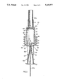
- FIG. 1 is a partially cut away side view of a preferred embodiment of a liquid dispenser with the reservoir and pump assembly in accordance with the present invention
- FIG. 2 is a partially exploded perspective view of the preferred embodiment of the pump assembly shown in FIG. 1;
- FIG. 3 is a cross sectional side view of an assembled pump assembly of FIG. 2;
- FIG. 4 is a cross sectional side view similar to FIG. 3 but with the dispensing piston in the fully inserted position;
- FIG. 5 is a cross sectional side view similar to FIG. 3 but with the dispensing piston in a partially extended position in a withdrawn stroke;
- FIG. 6 is a cross sectional side view similar to FIG. 3 but with the dispensing piston in a fully withdrawn position;
- FIG. 7 is a cross sectional side view similar to FIG. 3 but with the dispensing piston in a partially inserted position in a return stroke.
- FIGS. 2 and 3 show a pump assembly generally indicated 10.
- Pump assembly 10 is best shown in FIG. 2 as comprising three principle elements, a piston chamber forming body 12, a one-way valve 14 and a piston 16.
- body 12 has a cylindrical inner chamber 18 with the one-way valve 14 secured at an inner end 24 of the chamber 18.
- Piston 16 is axially slidably received in chamber 18 for reciprocal sliding movement inwardly and outwardly of an open end 22 of chamber 18.
- Body 12 not only carries the one-way valve 14 and piston 16 but is also adapted to be frictionally engaged into a cylindrical neck 34 of the fluid reservoir 26 shown in FIG. 1. With the pump assembly 10 coupled to reservoir 26, reciprocal movement of piston 16 will pump fluid from the reservoir 26 through piston 16.
- body 12 is generally cylindrical in cross-section and symmetrical about its central axis.
- Body 12 has an inner cylindrical portion 41 forming the chamber 18 and, disposed coaxially thereabout and spaced therefrom an outer cylindrical portion 40.
- the inner and outer cylindrical portions are joined by a disc-like rim 38 extending radially outwardly about open end 22 of chamber 18.
- Sealing and gripping flanges 36 are provided about the outer cylindrical portion 40 to assist in frictionally engaging the inner surfaces of reservoir neck 34 and form a fluid impermeable seal therewith.
- Rim 38 continues radially outwardly past flanges 36 as stop flange 39 which serve to limit insertion of body 12 into reservoir neck 34.
- Chamber 18 is disposed coaxially within inner cylindrical portion 40, with the chamber 18 terminating at its inner end 24 at a radially inwardly extending inner shoulder 30 with a central opening 25 therethrough.
- Hollow, cylindrical intake extension 32 shown as being of a lesser diameter extends axially away from shoulder 30.
- One-way valve 14 is best shown in FIG. 2 to comprise an annular ring 42 having a coaxially located flexible circular flap 44 hingely connected thereto.
- the one-way valve 14 is slidably inserted into the 18 to abut the inner shoulder 30.
- one-way valve 14 is formed entirely of plastic and is formed by injection molding.
- the abutting inner shoulder 30 disposed between the one-way valve 14 and the reservoir 26 is sized having a smaller radius than the radius of the circular flap 44, so as to prevent bending of the circular flap 44 inward towards the reservoir 26.
- the circular flap 44 is free to bend outwardly and thus permit only outward flow of fluid 28 from the reservoir 26 into chamber 18.
- the chamber 18 and one-way valve 14 are assembled such that the circumferential surface of annular ring 42 engages the chamber wall 20 in a friction fit relationship.
- piston 16 is generally cylindrical in cross section and adapted to be slidably received in chamber 18.
- Piston 16 is a unitary element formed entirely of plastic preferably by injection molding.
- Piston 16 has a central hollow stem 46 extending along the central longitudinal axis of the piston 16.
- a circular resilient flexing disc 48 is located at the inward most end of the piston 16 and extends radially therefrom. Flexing disc 48 is sized to circumferentially abut the cylindrical inner chamber wall 20 substantially preventing fluid flow therebetween.
- a circular sealing disc 50 is located on the stem 46 spaced axially outwardly from the flexing disc 48.
- the sealing disc 50 extends radially outward from the stem 46 to circumferentially engage the chamber wall 20 to form a substantially fluid impermeable seal therebetween.
- Sealing disc 50 is formed sufficiently rigid so as to resist deformation, maintaining a substantially fluid impermeable seal with the chamber wall 20 on sliding the piston 16 in and out of the chamber 18.
- Piston stem 46 has a central hollow passage 52 extending along the axis of the piston 16 from an inner end located in the stem 46 between the flexing disc 48 and the sealing disc 50, to an outlet 54 at the outer end of the piston 16.
- a channel 56 passes from inlets 58 located on either side of the stem 46 between the flexing disc 48 and the sealing disc 50, radially inward through the piston 16 to communicate with central passage 52.
- the channel 56 and central passage 52 permit fluid communication through the piston 16, past the sealing disc 50, between the inlets 58 and the outlet 54.
- an outer circular engagement flange 62 is provided on the outermost end of the stem 46 which extends radially outwardly from about the outlet 54. As discussed later flange 62 may be engaged by an actuating device in order to move the piston 16 in and out of the body 12.
- a circular stopping disc 64 is provided on the stem 46 between the flange 62 and the sealing disc 50 extending radially outward from the stem 46. Stopping disc 64 has a radius greater than the radius of the chamber 18 such that the stopping disc 64 limits inward movement of piston 16 by abutment of the stopping disc 64 with rim 38 about outer end 22 of the body 18.
- Axially extending webs 66 and circumferential ribs 67 are provided to extend radially from stem 46. These webs 66 and rib 67 engage chamber wall 20 so as to assist in maintaining the piston 16 in an axially centered and aligned position when sliding in and out of the chamber 18.
- FIG. 4 shows the pump assembly with piston 16 in a fully retracted position.
- FIG. 6 shows the pump assembly with piston 16 in a fully withdrawn position.
- FIG. 5 shows the pump assembly with piston 16 during a withdrawn stroke moving in the direction of arrow 118 from the retracted position of FIG. 4 to the withdrawn position of FIG. 6.
- FIG. 7 shows the pump assembly with piston 16 during a return stroke moving in the direction of arrow 120 from the withdrawn position of FIG. 6 to the retracted position of FIG. 4.
- Repeated pumping action results by repeatedly cycling the pump assembly through the positions in sequence of FIGS. 4, 5, 6 and 7.
- the flexing disc 48 needs on one hand to substantially prevent flow therepast in the withdrawal stroke and on the other hand deform to permit flow therepast in the return stroke.
- the disc 48 shown facilitates this by being formed as a thin resilient disc in effect having an elastically deformable edge portion near chamber wall 20.
- flexing disc 48 When not deformed flexing disc 48 abuts chamber wall 20 to form a substantially fluid impermeable seal. When deformed, as by its edge portion being bent away from wall 20, fluid may flow past the disc.
- Disc 48 is deformed when the pressure differential across it, that is the difference between the pressure on one side and the pressure on the other side, is greater than a maximum pressure differential which the disc can withstand without deflecting. When the pressure differential is greater than this maximum pressure differential, the disc deforms and fluid flows past. When the pressure differential reduces to less than this maximum pressure differential, the disc returns to its original shape substantially forming a seal with wall 20.
- the overall configuration of the pump assembly needs to be considered to achieve best results.
- the resistance of fluid flow into chamber 18 past the one-way valve 14 compared to the resistance to fluid flow back up channel 56 and passage 52 will affect the relative pressures on each side of the disc 48 and whether the disc will be deflected.
- the pump assembly is to be designed having regard to the viscosity of the fluid, the resistance to flow outwardly through one-way valve and the resistance to flow back inwardly through the piston 16 as well as the relative resiliency of the disc 48 so that in operation the flexing disc prevents fluid flow therepast in the outward stroke yet permits fluid flow therepast in the return stroke.
- Disc 48 may be designed to resist deformation in one direction compared to the other so as to assist in achieving the desired operation.
- FIG. 1 shows a liquid soap dispenser generally indicated 70 utilizing pump assembly 10 and reservoir 26 with pump assembly 10 inserted into neck 34 of reservoir 26.
- Dispenser 70 has a housing generally indicated 78 to receive and support the pump assembly 10 and reservoir 26. Housing 78 is shown with a back plate 80 for mounting the housing, for example to a building wall 82.
- a bottom support plate 84 extends forwardly from the back plate to receive and support the reservoir 26 and pump assembly 10. As shown bottom support plate 84 has a circular opening 86 therethrough.
- the reservoir 26 sits, supported on plate 79 with its neck 34 extending through opening 86 and secured in the opening as by friction fit, clamping and the like.
- a cover member 85 is hinged to an upper forward extension 87 of back plate 80, so as to permit replacement of reservoir 26 and its pump assembly 10.
- Bottom plate 84 carries at a forward portion thereof an actuating lever 88 journalled for pivoting about a horizontal axis at 90.
- An upper end of lever 88 carries a hook 94 to engage engagement flange 62 and couple lever 88 to piston 16, such that movement of the lower handle end 96 of lever 88 from the solid to the dotted line position, in the direction indicated by arrow 98 slides piston inwardly in a return, pumping stroke as indicated by arrow 100.
- spring 102 biases the upper portion of lever 88 downwardly, so that the lever 88 draws piston 16 outwardly to a fully withdrawn position as seen in solid lines in FIG. 1.
- Lever 88 and its inner hook 94 are adapted to permit manually coupling and uncoupling of the hook 94 as is necessary to remove and replace reservoir 26 and pump assembly 10.
- the dispenser 70 In use of the dispenser 70, once exhausted the empty reservoir 26 together and attached pump 10 is removed and a new reservoir 26 and attached pump 10 are inserted into the housing.
- the removed reservoir 26 and attached pump 10 is made entirely of recyclable plastic material which may easily be recycled without the need for disassembly prior to cutting and shredding.
- FIG. 3 shows two tubular extensions of the pump assembly which are not shown in the other Figures.
- an inlet extension tube 33a may be provided as a separate cylindrical plastic tube which has an outer diameter sized to frictionally engage in sealed relation in hollow, cylindrical intake extension 32.
- Such an intake extension tube 33a may be necessary if the pump assembly is used in a dispenser configuration not shown as where the fluid level is either below the pump assembly or spaced from the pump assembly.
- an outlet extension tube 52a may be provided as a separate cylindrical plastic tube which has an outer diameter sized to frictionally engage in sealed relation in a hollow cylindrical portion 53 of channel 52 in the stem 46 of the piston 16.
- Such an outlet extension tube 52a may be useful to direct more particularly the location of discharge of the pump, or if the pump pumps fluid upwardly, when the tube may be bent as a spout.
- FIG. 2 shows a plastic cylindrical piston-chamber 12 and piston 16
- piston-chambers and pistons of other symmetrical and non-symmetrical shapes and materials may also be used.
- piston-chamber 12 having a stop flange 39 and outer cylindrical portion 40 having gripping flanges 36 is preferred, the gripping flanges 36 or other gripping means could be provided elsewhere on the piston-chamber 12.
- FIG. 3 shows a channel 56 passing from an inlet 58 on the stem 46 of the piston 16 and connecting with an axially aligned central passage 52
- the channel 56 could also be provided permitting fluid communication outward past the sealing disc 50 without connecting with a central passage and without an inlet 58 disposed on the stem 46 of the piston 16.
Abstract
A disposable plastic pump for dispensing liquids is disclosed which comprises three basic unitary all plastic elements: a chamber forming body having an open outer end and an inner end in fluid communication with a liquid reservoir, a one-way valve located at the inner end of the chamber between the reservoir and the chamber permitting fluid flow only from the reservoir into the chamber, and a piston formed to slidably fit into the chamber. The piston comprises a stem on which is located an inwardly located flexing element serving as a one-way valve to permit fluid flow outwardly past the flexing element and a sealing element located outwardly of the flexing element. A channel is provided from an inlet on the piston between the flexing element and the sealing element through which the dispensed liquid flows.
Description
This invention relates generally to a disposable plastic pump, and more particularly to an inexpensive all plastic, disposable pump assembly for dispensing hand soap.
Many pump assemblies are known for dispensing hand soap. Typically even the simplest of these assemblies include at least four separate elements, a chamber forming body, two one-way valves and a piston. These pumps suffer the disadvantage that they have a number of individual parts and costs typically increase with the number of parts and the assembly required.
Known disposable pump assemblies for dispensing hand soap typically include at least some metal parts such as metal balls for one-way valves and metal springs to bias one-way valves closed. The inclusion of metal parts suffers the disadvantage that the pump assemblies can not merely be ground up in plastic grinders for recycling in that the metal parts are not compatible with most plastic grinding machines.
Known hand soap dispensing systems provide replaceable receptacles for liquid soap with permanent pump assemblies to pump soap from the receptacles. This has the disadvantage that the pumps are expensive and after prolonged usage may fail or require cleaning and maintenance.
To at least partially overcome these disadvantages of known liquid containers and pumps, the present invention provides a pump assembly for dispensing liquids with a novel, unitary construction for a piston so that the pump will have as few separate parts as possible, preferably fewer than four, which may be easily assembled.
Another object is to provide a unique configuration for an inexpensive disposable piston for a disposable pump which can be injection molded, as a unitary element entirely from plastic yet incorporate a one-way valve.
Another object is to provide a disposable plastic pump assembly formed entirely from three unitary plastic elements without any metal parts.
Another object is to provide a system for dispensing hand soap comprising a permanent housing and pump activator and a disposable soap reservoir and pump assembly.
Another object is to provide a disposable pump for dispensing liquids, adapted to be used with a disposable fluid container, which may be readily recycled without first requiring disassembly of the parts of the pump prior to crushing or shredding of the disposed container-pump assembly.
The present invention provides an inexpensive, easy to assemble, disposable pump for dispensing liquids, which is readily adapted to fit in a friction fit manner into the neck of a liquid reservoir, preferably a disposable reservoir. The pump comprises three basic unitary elements: a chamber forming body, a one-way valve and a piston. The body forms a chamber having an open outer end and an inner end which is in fluid communication with the reservoir. A one-way valve is located at the inner end of the chamber between the reservoir and the chamber, permitting fluid flow only from the reservoir into the piston-chamber.
The piston is formed to be slidably received in the piston-chamber and comprises a stem. A flexing element, which serves as a one-way valve permitting fluid flow only outwardly past the flexing element is located inwardly on the stem. A sealing element which forms a substantially fluid impermeable seal between the sealing element and the piston-chamber is located outward on the stem from the flexing element. A channel is provided from an inlet on the piston between the flexing element and the sealing element to permit fluid flow to an outlet outward of the sealing means.
Liquids are drawn from the reservoir by the outward and inward movement of the piston. Outward movement causing fluids to pass from the reservoir, through the one-way valve and into the piston-chamber. Inward movement causing the one-way valve to close and the flexing element to bend allowing liquid to pass outwardly via the channel.
After exhaustion of the liquids contained in the reservoir, the reservoir is replaced, preferably together with a new pump assembly attached.
Preferably both the reservoir and the pump are formed entirely of plastic so as to permit easy recycling of the plastic parts.
The piston is provided with a unique combination of features which permits it to be injection molded from plastic as a unitary element yet incorporate a one-way valve.
The present invention also provides for a system for dispensing liquids having: a disposable plastic element suitable for recycling comprising a disposable liquid reservoir and a disposable pump assembly each formed entirely out of recyclable plastic, and a permanent non-disposable housing for the reservoir and pump assembly including a permanent actuating system to operate the pump assembly. Any non-recycleable or metal parts are incorporated into the permanent housing to ensure the disposable parts can be readily recycled.
Accordingly, in one of its aspects, this invention provides for a pump for dispensing liquids from a reservoir comprising a piston-chamber forming element having a cylindrical chamber, said chamber having a chamber wall, an outer open end and an inner end in fluid communication with the reservoir, one-way valve means between the reservoir and the chamber permitting fluid flow through an inner end of said chamber, only from the reservoir to the chamber, a piston forming element slidably received in the chamber extending outwardly from the open end thereof, said piston forming element comprising flexing means, sealing means, and channel means, the sealing means engaging the chamber wall circumferentially thereabout to form a substantially fluid impermeable seal therewith on sliding of said piston element inwardly and outwardly, the flexing means spaced inwardly on said piston element from the sealing means, the channel means providing fluid communication through said piston element from an inlet on the piston means between the flexing means and the sealing means, to an outlet on the piston means outward of the sealing means, the flexing means having an elastically deformable edge portion proximate the chamber wall circumferentially thereabout, wherein in operation, on the piston forming element sliding outwardly in said chamber the flexing means substantially preventing fluid flow past the flexing means in an inward direction, and on the piston forming element sliding inwardly into the chamber the flexing means elastically deforms away from the chamber wall to permit fluid flow past the flexing means in an outward direction, the piston forming element consisting of a unitary element formed entirely of plastic by injection molding.
In another of its aspects, this invention provides for a pump for dispensing liquids from a reservoir, comprising a piston-chamber forming element having a chamber with a chamber wall, an outer open end and an inner end in fluid communication with the reservoir, one-way valve means between the reservoir and the chamber permitting fluid flow only from the reservoir to the chamber, a piston forming element slidably received in the chamber extending outwardly from the open end thereof, said piston forming element comprising flexing means, sealing means, flange means and channel means, the sealing means engaging the chamber wall circumferentially thereabout to form a substantially fluid impermeable seal therewith on sliding of said piston element inwardly and outwardly, the flexing means spaced inwardly on said piston element from the sealing means, the flange means spaced outwardly on said piston element from the sealing means, the channel means providing fluid communication through said piston element from an inlet on the piston means between the flexing means and the sealing means, to an outlet on the piston means outward of the sealing means, the flexing means having an elastically deformable edge portion proximate the chamber wall circumferentially thereabout, wherein in operation on the piston forming element sliding outwardly in said chamber the flexing means substantially prevents fluid flow past the flexing means in an inward direction, and on the piston forming element sliding inwardly into the chamber the flexing means elastically deforms away from the chamber wall to permit fluid flow past the flexing means in an outward direction, each of the piston-chamber forming element, the one-way valve and the piston forming element consisting of a unitary element formed by injection molding said reservoir having an open neck adapted to receive said pump in a friction fit manner, an actuating lever formed to engage the flange means to slidably move said piston within said chamber spring means adapted to return said actuating lever to a rest position, housing adapted to permanently receive and retain said actuating lever and said spring means.
Further objects and advantages of the invention will appear from the following description taken together with the accompanying drawings in which:
FIG. 1 is a partially cut away side view of a preferred embodiment of a liquid dispenser with the reservoir and pump assembly in accordance with the present invention;
FIG. 2 is a partially exploded perspective view of the preferred embodiment of the pump assembly shown in FIG. 1;
FIG. 3 is a cross sectional side view of an assembled pump assembly of FIG. 2;
FIG. 4 is a cross sectional side view similar to FIG. 3 but with the dispensing piston in the fully inserted position;
FIG. 5 is a cross sectional side view similar to FIG. 3 but with the dispensing piston in a partially extended position in a withdrawn stroke;
FIG. 6 is a cross sectional side view similar to FIG. 3 but with the dispensing piston in a fully withdrawn position; and
FIG. 7 is a cross sectional side view similar to FIG. 3 but with the dispensing piston in a partially inserted position in a return stroke.
Reference is made first to FIGS. 2 and 3 which show a pump assembly generally indicated 10. Pump assembly 10 is best shown in FIG. 2 as comprising three principle elements, a piston chamber forming body 12, a one-way valve 14 and a piston 16.
In essence body 12 has a cylindrical inner chamber 18 with the one-way valve 14 secured at an inner end 24 of the chamber 18. Piston 16 is axially slidably received in chamber 18 for reciprocal sliding movement inwardly and outwardly of an open end 22 of chamber 18. Body 12 not only carries the one-way valve 14 and piston 16 but is also adapted to be frictionally engaged into a cylindrical neck 34 of the fluid reservoir 26 shown in FIG. 1. With the pump assembly 10 coupled to reservoir 26, reciprocal movement of piston 16 will pump fluid from the reservoir 26 through piston 16.
As seen in FIG. 2 body 12 is generally cylindrical in cross-section and symmetrical about its central axis. Body 12 has an inner cylindrical portion 41 forming the chamber 18 and, disposed coaxially thereabout and spaced therefrom an outer cylindrical portion 40. The inner and outer cylindrical portions are joined by a disc-like rim 38 extending radially outwardly about open end 22 of chamber 18. Sealing and gripping flanges 36 are provided about the outer cylindrical portion 40 to assist in frictionally engaging the inner surfaces of reservoir neck 34 and form a fluid impermeable seal therewith. Rim 38 continues radially outwardly past flanges 36 as stop flange 39 which serve to limit insertion of body 12 into reservoir neck 34.
One-way valve 14 is best shown in FIG. 2 to comprise an annular ring 42 having a coaxially located flexible circular flap 44 hingely connected thereto. In assembly, as seen in FIG. 3 the one-way valve 14 is slidably inserted into the 18 to abut the inner shoulder 30. Preferably, one-way valve 14 is formed entirely of plastic and is formed by injection molding. The abutting inner shoulder 30 disposed between the one-way valve 14 and the reservoir 26 is sized having a smaller radius than the radius of the circular flap 44, so as to prevent bending of the circular flap 44 inward towards the reservoir 26. The circular flap 44 is free to bend outwardly and thus permit only outward flow of fluid 28 from the reservoir 26 into chamber 18. The chamber 18 and one-way valve 14 are assembled such that the circumferential surface of annular ring 42 engages the chamber wall 20 in a friction fit relationship.
As best seen in FIG. 2, piston 16 is generally cylindrical in cross section and adapted to be slidably received in chamber 18. Piston 16 is a unitary element formed entirely of plastic preferably by injection molding. Piston 16 has a central hollow stem 46 extending along the central longitudinal axis of the piston 16. A circular resilient flexing disc 48 is located at the inward most end of the piston 16 and extends radially therefrom. Flexing disc 48 is sized to circumferentially abut the cylindrical inner chamber wall 20 substantially preventing fluid flow therebetween.
A circular sealing disc 50 is located on the stem 46 spaced axially outwardly from the flexing disc 48. The sealing disc 50 extends radially outward from the stem 46 to circumferentially engage the chamber wall 20 to form a substantially fluid impermeable seal therebetween. Sealing disc 50 is formed sufficiently rigid so as to resist deformation, maintaining a substantially fluid impermeable seal with the chamber wall 20 on sliding the piston 16 in and out of the chamber 18.
As best shown in FIGS. 2 and 3, an outer circular engagement flange 62 is provided on the outermost end of the stem 46 which extends radially outwardly from about the outlet 54. As discussed later flange 62 may be engaged by an actuating device in order to move the piston 16 in and out of the body 12.
A circular stopping disc 64 is provided on the stem 46 between the flange 62 and the sealing disc 50 extending radially outward from the stem 46. Stopping disc 64 has a radius greater than the radius of the chamber 18 such that the stopping disc 64 limits inward movement of piston 16 by abutment of the stopping disc 64 with rim 38 about outer end 22 of the body 18.
Operation of the pump assembly 10 is now described with particular reference to FIGS. 4, 5, 6 and 7. FIG. 4 shows the pump assembly with piston 16 in a fully retracted position. FIG. 6 shows the pump assembly with piston 16 in a fully withdrawn position. FIG. 5 shows the pump assembly with piston 16 during a withdrawn stroke moving in the direction of arrow 118 from the retracted position of FIG. 4 to the withdrawn position of FIG. 6. FIG. 7 shows the pump assembly with piston 16 during a return stroke moving in the direction of arrow 120 from the withdrawn position of FIG. 6 to the retracted position of FIG. 4. Repeated pumping action results by repeatedly cycling the pump assembly through the positions in sequence of FIGS. 4, 5, 6 and 7.
During the withdrawal or out stroke of FIG. 5, the withdrawal of the piston causes one-way valve 14 to open with fluid to flow into chamber 18 past open flap 44. In the withdrawal stroke flexing disc 48 remains substantially undeflected and assists in creating suction forces in chamber 18 to open flap 44 and draw fluid into chamber 18 past flap 44.
During the return stroke of FIG. 7, the return of piston 16 pressurizes fluid in chamber 18 between the piston and one-way valve 14. This pressure urges flap 44 to a closed position abutting shoulder 30. As a result of this pressure, flexing disc 48 deflects a its periphery as indicated in FIG. 7 so as to come out of sealing engagement with chamber walls 20 and permit fluid to flow past disc 48 and out of chamber 18 via passage 52 and channel 56 and passage 52.
The flexing disc 48 needs on one hand to substantially prevent flow therepast in the withdrawal stroke and on the other hand deform to permit flow therepast in the return stroke. The disc 48 shown facilitates this by being formed as a thin resilient disc in effect having an elastically deformable edge portion near chamber wall 20.
When not deformed flexing disc 48 abuts chamber wall 20 to form a substantially fluid impermeable seal. When deformed, as by its edge portion being bent away from wall 20, fluid may flow past the disc. Disc 48 is deformed when the pressure differential across it, that is the difference between the pressure on one side and the pressure on the other side, is greater than a maximum pressure differential which the disc can withstand without deflecting. When the pressure differential is greater than this maximum pressure differential, the disc deforms and fluid flows past. When the pressure differential reduces to less than this maximum pressure differential, the disc returns to its original shape substantially forming a seal with wall 20.
With a simple disc 48 of thin plastic as shown, the overall configuration of the pump assembly needs to be considered to achieve best results. For example, in a withdrawal stroke, the resistance of fluid flow into chamber 18 past the one-way valve 14 compared to the resistance to fluid flow back up channel 56 and passage 52 will affect the relative pressures on each side of the disc 48 and whether the disc will be deflected. Preferably the pump assembly is to be designed having regard to the viscosity of the fluid, the resistance to flow outwardly through one-way valve and the resistance to flow back inwardly through the piston 16 as well as the relative resiliency of the disc 48 so that in operation the flexing disc prevents fluid flow therepast in the outward stroke yet permits fluid flow therepast in the return stroke.
Reference is now made to FIG. 1 which shows a liquid soap dispenser generally indicated 70 utilizing pump assembly 10 and reservoir 26 with pump assembly 10 inserted into neck 34 of reservoir 26. Dispenser 70 has a housing generally indicated 78 to receive and support the pump assembly 10 and reservoir 26. Housing 78 is shown with a back plate 80 for mounting the housing, for example to a building wall 82. A bottom support plate 84 extends forwardly from the back plate to receive and support the reservoir 26 and pump assembly 10. As shown bottom support plate 84 has a circular opening 86 therethrough. The reservoir 26 sits, supported on plate 79 with its neck 34 extending through opening 86 and secured in the opening as by friction fit, clamping and the like. A cover member 85 is hinged to an upper forward extension 87 of back plate 80, so as to permit replacement of reservoir 26 and its pump assembly 10.
In use of the dispenser 70, once exhausted the empty reservoir 26 together and attached pump 10 is removed and a new reservoir 26 and attached pump 10 are inserted into the housing. Preferably, the removed reservoir 26 and attached pump 10 is made entirely of recyclable plastic material which may easily be recycled without the need for disassembly prior to cutting and shredding.
FIG. 3 shows two tubular extensions of the pump assembly which are not shown in the other Figures.
Firstly an inlet extension tube 33a may be provided as a separate cylindrical plastic tube which has an outer diameter sized to frictionally engage in sealed relation in hollow, cylindrical intake extension 32. Such an intake extension tube 33a may be necessary if the pump assembly is used in a dispenser configuration not shown as where the fluid level is either below the pump assembly or spaced from the pump assembly.
Secondly an outlet extension tube 52a may be provided as a separate cylindrical plastic tube which has an outer diameter sized to frictionally engage in sealed relation in a hollow cylindrical portion 53 of channel 52 in the stem 46 of the piston 16. Such an outlet extension tube 52a may be useful to direct more particularly the location of discharge of the pump, or if the pump pumps fluid upwardly, when the tube may be bent as a spout.
While the preferred embodiment of FIG. 2 shows a plastic cylindrical piston-chamber 12 and piston 16, piston-chambers and pistons of other symmetrical and non-symmetrical shapes and materials may also be used.
Although a piston-chamber 12 having a stop flange 39 and outer cylindrical portion 40 having gripping flanges 36 is preferred, the gripping flanges 36 or other gripping means could be provided elsewhere on the piston-chamber 12.
While the preferred embodiment of FIG. 3 shows a channel 56 passing from an inlet 58 on the stem 46 of the piston 16 and connecting with an axially aligned central passage 52, the channel 56 could also be provided permitting fluid communication outward past the sealing disc 50 without connecting with a central passage and without an inlet 58 disposed on the stem 46 of the piston 16.
Although the disclosure describes and illustrates a preferred embodiment of the invention it is to be understood that the invention is not limited to these particular embodiments. Many variations and modifications will now occur to those skilled in the art.
Claims (12)
1. A pump for dispensing liquids from a reservoir, comprising:
(a) a piston-chamber forming element having a cylindrical chamber, said chamber having a chamber wall, an outer open end and an inner end in fluid communication with the reservoir;
(b) one-way valve means between the reservoir and the chamber permitting fluid flow through the inner end of said chamber, only from the reservoir to the chamber;
(c) a piston forming element slidably received in the chamber extending outwardly from the open end thereof;
said piston forming element being generally cylindrical in cross-section with a central axially extending hollow stem having a central passageway open at an outer end forming an outlet and closed at an inner end;
a circular flexing disc extending radially outwardly from the stem proximate the inner end, the flexing disc having an elastically deformable edge portion proximate the chamber wall circumferentially thereabout,
a circular sealing disc extending radially outwardly from the stem spaced axially outwardly from the flexing disc, the sealing disc engaging the chamber wall circumferentially thereabout to form a substantially fluid impermeable seal therewith on sliding of said piston forming element inwardly and outwardly,
an inlet located on the stem between the flexing disc and sealing disc in communication with the passageway via a short channel extending radially inward from the inlet to the passageway,
engagement means on said stem outward of the chamber forming element for engagement to move the piston forming element inwardly and outwardly,
locating means on said stem extending radially outwardly from the stem to engage said chamber wall and guide the piston forming element in sliding axially centered and aligned within the chamber,
the locating means comprising a plurality of axially extending webs,
wherein in operation,
(i) on the piston forming element sliding outwardly in said chamber, the flexing disc substantially preventing fluid flow past the flexing disc in an inward direction, and
(ii) on the piston forming element sliding inwardly into the chamber the flexing disc elastically deforms away from the chamber wall to permit fluid flow past the flexing disc in an outward direction.
2. A pump as claimed in claim 1 including a hollow cylindrical dispensing extension tube,
said passageway sized to receive an inner end of the dispensing extension tube in sliding force-fit relation.
3. A pump as claimed in claim 1 wherein the engagement means comprises a circular flange extending radially outwardly from about the outermost end of said stem.
4. A pump as claimed in claim 3 including means provided on said stem to stop inward movement of the piston forming element by abutment with the piston-chamber forming element,
the stop means comprising a circular disc extending radially outwardly form the stem spaced outwardly of the sealing disc and having a radius greater than that of the chamber.
5. A pump as claimed in claim 4 wherein the piston forming element consists of a unitary element formed entirely of plastic by injection molding.
6. A pump as claimed in claim 1 wherein the piston-chamber forming element is generally cylindrical in cross-section,
the chamber ending at an inner shoulder with a coaxial smaller diameter inwardly extending hollow cylindrical intake extension formed integrally therewith,
the one-way valve means slidably received in friction fit relation in the chamber proximate the inner shoulder.
7. A pump as claimed in claim 6 wherein the one-way valve means comprises an annular ring with a flexible circular flap formed entirely of plastic by injection molding.
8. A pump as claimed in 7 wherein the piston-chamber forming element having an inner cylindrical portion forming said chamber and cylindrical intake extension,
stop flange means extending radially outwardly from about the outer end of the chamber,
an outer cylindrical portion extending from the stop flange inwardly coaxially about the inner cylindrical portion spaced coaxially thereabout
a radially outer surface of the outer cylindrical portion adapted to frictionally engage in fluid sealing relationship an opening in said reservoir.
9. A pump as claimed in 8 wherein said piston-chamber forming element is formed entirely of plastic by injection molding.
10. A pump as claimed in claim 6 including a hollow outer extension tube, the cylindrical extension having a section sized to receive an outer end of the outlet tube in sliding force-fit relation.
11. A pump as claimed in claim 1 wherein the piston forming element consists of a unitary element formed entirely of plastic by injection molding.
12. A unit for dispensing liquids comprising in combination:
(i) a pump as claimed in claim 1;
(ii) a reservoir for the liquids;
(iii) housing means;
said pump and reservoir formed entirely from plastic material which may be recycled by shredding or cutting without disassembly,
the reservoir having an open neck adopted to receive said pump in a friction fit manner,
the housing means removably supporting said reservoir and pump and including an actuation lever to engage the engagement means of said piston forming element to slidably move said piston forming element within the chamber,
spring means adapted to return said actuating lever to a rest position,
said housing means adapted to permanently receive and retain said actuating lever and said spring means.
Priority Applications (6)
| Application Number | Priority Date | Filing Date | Title |
|---|---|---|---|
| US07/702,937 US5165577A (en) | 1991-05-20 | 1991-05-20 | Disposable plastic liquid pump |
| CA002045313A CA2045313C (en) | 1991-05-20 | 1991-06-24 | Disposable plastic liquid pump |
| US07/980,208 US5282552A (en) | 1991-05-20 | 1992-11-23 | Disposable plastic liquid pump |
| US08/355,920 US5489044A (en) | 1991-05-20 | 1994-12-14 | Method of preparing replaceable liquid soap reservoir |
| US08/541,370 US5676277A (en) | 1991-05-20 | 1995-10-10 | Disposable plastic liquid pump |
| US08/874,688 US5975360A (en) | 1991-05-20 | 1997-06-13 | Capped piston pump |
Applications Claiming Priority (1)
| Application Number | Priority Date | Filing Date | Title |
|---|---|---|---|
| US07/702,937 US5165577A (en) | 1991-05-20 | 1991-05-20 | Disposable plastic liquid pump |
Related Child Applications (1)
| Application Number | Title | Priority Date | Filing Date |
|---|---|---|---|
| US07/980,208 Continuation-In-Part US5282552A (en) | 1991-05-20 | 1992-11-23 | Disposable plastic liquid pump |
Publications (1)
| Publication Number | Publication Date |
|---|---|
| US5165577A true US5165577A (en) | 1992-11-24 |
Family
ID=24823229
Family Applications (1)
| Application Number | Title | Priority Date | Filing Date |
|---|---|---|---|
| US07/702,937 Expired - Lifetime US5165577A (en) | 1991-05-20 | 1991-05-20 | Disposable plastic liquid pump |
Country Status (2)
| Country | Link |
|---|---|
| US (1) | US5165577A (en) |
| CA (1) | CA2045313C (en) |
Cited By (100)
| Publication number | Priority date | Publication date | Assignee | Title |
|---|---|---|---|---|
| US5282552A (en) * | 1991-05-20 | 1994-02-01 | Hygiene-Technik Inc. | Disposable plastic liquid pump |
| US5373970A (en) * | 1993-10-29 | 1994-12-20 | Hygiene-Technik Inc. | Liquid soap dispenser for simplified replacement of soap reservoir |
| WO1995003246A1 (en) * | 1993-07-26 | 1995-02-02 | Merck & Co., Inc. | Liquid dispenser having a dosage counter |
| US5445288A (en) * | 1994-04-05 | 1995-08-29 | Sprintvest Corporation Nv | Liquid dispenser for dispensing foam |
| US5489044A (en) * | 1991-05-20 | 1996-02-06 | Hygiene-Technik Inc. | Method of preparing replaceable liquid soap reservoir |
| GB2302087A (en) * | 1995-06-09 | 1997-01-08 | Body Shop Int Plc | Dispensing apparatus |
| US5615801A (en) * | 1990-06-06 | 1997-04-01 | The Coca-Cola Company | Juice concentrate package for postmix dispenser |
| WO1997013439A1 (en) * | 1995-10-10 | 1997-04-17 | Heiner Ophardt | Rear entry stepped pump |
| WO1997015223A1 (en) * | 1995-10-23 | 1997-05-01 | Unilever N.V. | Liquid dispenser |
| US5803312A (en) * | 1994-06-08 | 1998-09-08 | The Coca-Cola Company | Manually operable postmix juice dispenser and disposable concentrate package therefor |
| US5826755A (en) * | 1995-12-18 | 1998-10-27 | Koller Enterprises, Inc. | Liquid dispenser with selectably attachable actuator |
| US5842603A (en) * | 1990-06-06 | 1998-12-01 | The Coca-Cola Company | Postmix juice dispenser |
| US5855302A (en) * | 1996-12-18 | 1999-01-05 | Georgia-Pacific Corporation | Liquid dispensing cap valve assembly with pedestal mounted resilient valve seal element |
| US5975360A (en) * | 1991-05-20 | 1999-11-02 | Ophardt; Heiner | Capped piston pump |
| US5992698A (en) * | 1995-08-07 | 1999-11-30 | Ecolab Inc. | Liquid soap dispenser |
| WO2000004812A1 (en) * | 1998-07-22 | 2000-02-03 | Vendor B.V. | Dosing device for dispensing a viscous substance, for instance an antiseptic fluid, and container for such dosing device |
| US6068162A (en) * | 1999-02-18 | 2000-05-30 | Avmor Ltd. | Adjustable soap dispenser |
| US6082586A (en) * | 1998-03-30 | 2000-07-04 | Deb Ip Limited | Liquid dispenser for dispensing foam |
| US6247621B1 (en) | 1998-09-30 | 2001-06-19 | Kimberly-Clark Worldwide, Inc. | Dual use dispensing system |
| US6343724B1 (en) | 2000-07-10 | 2002-02-05 | Hygiene Technik Inc. | Unitary one-way valve for fluid dispenser |
| US6409050B1 (en) | 2001-03-20 | 2002-06-25 | Hygiene-Technik Inc. | Liquid dispenser for dispensing foam |
| US6516976B2 (en) | 2000-12-19 | 2003-02-11 | Kimberly-Clark Worldwide, Inc. | Dosing pump for liquid dispensers |
| US6533145B2 (en) | 2000-12-19 | 2003-03-18 | Kimberly-Clark Worldwide, Inc. | Self-contained viscous liquid dispenser |
| US6540157B2 (en) | 2001-04-12 | 2003-04-01 | Heiner Ophardt | Nozzle for fluid dispenser |
| US6540117B2 (en) | 2001-03-30 | 2003-04-01 | Kimberly-Clark Worldwide, Inc. | Dosing pump for liquid dispensers |
| US6557736B1 (en) | 2002-01-18 | 2003-05-06 | Heiner Ophardt | Pivoting piston head for pump |
| US20040056049A1 (en) * | 2000-09-07 | 2004-03-25 | Guiseppe Stradella | Multiple-dose device for dispensing a fluid product |
| US20040217137A1 (en) * | 2002-04-26 | 2004-11-04 | Heiner Ophardt | Manual or pump assist fluid dispenser |
| US20050051579A1 (en) * | 2003-09-10 | 2005-03-10 | Kasting Thomas P. | Inverted dispensing pump |
| US20050061832A1 (en) * | 2002-04-16 | 2005-03-24 | Heiner Ophardt | Vacuum relief device |
| US20050109798A1 (en) * | 2003-09-10 | 2005-05-26 | Kasting Thomas P. | Inverted dispensing pump with vent baffle |
| US20050161476A1 (en) * | 2002-04-26 | 2005-07-28 | Heiner Ophardt | One-way valve and vacuum relief device |
| US20050205600A1 (en) * | 2004-03-19 | 2005-09-22 | Heiner Ophardt | Dual component dispenser |
| US20050224519A1 (en) * | 2002-04-17 | 2005-10-13 | Law Brian R | Pump dispensers |
| US20060011655A1 (en) * | 2004-07-14 | 2006-01-19 | Heiner Ophardt | Sink side touchless foam dispenser |
| US20060175354A1 (en) * | 2002-04-26 | 2006-08-10 | Heiner Ophardt | Vacuum released valve |
| US20060175353A1 (en) * | 2005-02-09 | 2006-08-10 | Heiner Ophardt | Dispenser with side mounted activation levers |
| US20060237483A1 (en) * | 2005-04-22 | 2006-10-26 | Heiner Ophardt | Bellows dispenser |
| US20060249538A1 (en) * | 2005-04-22 | 2006-11-09 | Heiner Ophardt | Foam pump with spring |
| US20060261092A1 (en) * | 2005-05-19 | 2006-11-23 | Heiner Ophardt | Severable piston pump |
| US20060273114A1 (en) * | 2005-04-22 | 2006-12-07 | Heiner Ophardt | Stepped pump foam dispenser |
| US20070040296A1 (en) * | 2005-08-16 | 2007-02-22 | Moore Singleton C | Soap saver |
| US20070158363A1 (en) * | 2006-01-12 | 2007-07-12 | Heiner Ophardt | Fluid dispenser with sanitary nozzle |
| US20070194053A1 (en) * | 2002-04-26 | 2007-08-23 | Heiner Ophardt | Fire resistant container system |
| US20070257064A1 (en) * | 2006-05-05 | 2007-11-08 | Heiner Ophardt | Stepped cylinder piston pump |
| US20070284394A1 (en) * | 2006-06-13 | 2007-12-13 | Heiner Ophardt | Piston carrying guide tube |
| US20080135578A1 (en) * | 2006-11-09 | 2008-06-12 | Heiner Ophardt | Vacuum switch multi reservoir dispenser |
| EP2005871A2 (en) | 2007-06-22 | 2008-12-24 | Gotohti.com Inc. | Split engagement flange for soap dispenser pump piston |
| US20090101671A1 (en) * | 2007-10-22 | 2009-04-23 | Georgia-Pacific Consumer Products Lp | Pumping dispenser |
| US20090114679A1 (en) * | 2007-11-07 | 2009-05-07 | Heiner Ophardt | Collapsible bottle and cover |
| EP2067426A2 (en) | 2007-12-07 | 2009-06-10 | Gotohti.com Inc. | Angled slot foam dispenser |
| US20090184137A1 (en) * | 2006-04-26 | 2009-07-23 | O'brien Michael | Dispenser with Actuating Means Unengaged with the Dispensing Means |
| US20100059550A1 (en) * | 2008-09-11 | 2010-03-11 | Ciavarella Nick E | Pump having a flexible mechanism for engagement with a dispenser |
| US20100102091A1 (en) * | 2008-10-24 | 2010-04-29 | Andersen Daniel A | Barrier piston with seal |
| US20100140879A1 (en) * | 2008-12-05 | 2010-06-10 | Heiner Ophardt | Piston with guide rings |
| US20100140297A1 (en) * | 2008-12-08 | 2010-06-10 | Heiner Ophardt | Engagement flange for fluid dispenser pump piston |
| US20100206909A1 (en) * | 2007-09-21 | 2010-08-19 | O'brien Michael | Dispenser mechanism |
| US20100232997A1 (en) * | 2009-03-10 | 2010-09-16 | Heiner Ophardt | Doubled seal disk for piston pump |
| US20100301070A1 (en) * | 2008-02-18 | 2010-12-02 | Evonik Stockhausen Gmbh | Suction pump for a dispenser unit and dispenser unit |
| US20110014076A1 (en) * | 2009-07-14 | 2011-01-20 | Shi Zhenchun Tony | Draw back push pump |
| US20110147416A1 (en) * | 2005-02-14 | 2011-06-23 | Stockhausen Gmbh | Dispenser |
| US20110168740A1 (en) * | 2010-01-11 | 2011-07-14 | David John Pritchett | Inverted dispenser pump with liquid inlet cup valve |
| US8020734B1 (en) * | 2008-03-21 | 2011-09-20 | Vandendries Robert H | Hand washing timing system |
| US8113388B2 (en) | 2008-12-08 | 2012-02-14 | Heiner Ophardt | Engagement flange for removable dispenser cartridge |
| EP2446971A1 (en) | 2010-11-01 | 2012-05-02 | Gotohti.com Inc. | Telescopic piston for pump |
| CN1865123B (en) * | 2005-05-19 | 2012-07-11 | 哥特赫提.Com有限公司 | Frangible piston pump |
| EP2511889A2 (en) | 2011-04-08 | 2012-10-17 | Gotohti.Com Inc. | Dispenser with sound generators |
| US8336740B1 (en) | 2005-11-02 | 2012-12-25 | Daansen Warren S | Fluid dispenser and pump adapter system therefor |
| US8413852B2 (en) | 2008-12-08 | 2013-04-09 | Gotohti.Com Inc. | Ramped actuator for engagement flange on removable dispenser cartridge |
| EP2606793A2 (en) | 2011-12-22 | 2013-06-26 | Gotohti.Com Inc. | Ramp actuator for engagement flange on removable dispenser cartridge |
| US8528795B2 (en) | 2008-09-01 | 2013-09-10 | Rieke Corporation | Liquid dosing devices |
| US8556130B2 (en) | 2010-01-14 | 2013-10-15 | Rieke Corporation | Pump dispensers |
| EP2676737A1 (en) | 2012-06-19 | 2013-12-25 | Gotohti.com Inc. | Drawback check valve |
| EP2676736A1 (en) | 2012-06-19 | 2013-12-25 | Gotohti.Com Inc. | Telescopic bell piston for pump |
| US8651328B2 (en) | 2011-07-14 | 2014-02-18 | Georgia-Pacific Consumer Products Lp | Pumping dispenser shield |
| EP2700343A2 (en) | 2012-08-22 | 2014-02-26 | Gotohti.Com Inc. | Rotating keyed dispensing cartridge system |
| US8807398B2 (en) | 2010-04-22 | 2014-08-19 | Sca Hygiene Products Ab | Dispenser and liquid container |
| US8814005B2 (en) | 2012-04-27 | 2014-08-26 | Pibed Limited | Foam dispenser |
| US8827116B1 (en) | 2013-09-25 | 2014-09-09 | George Wesley Hamilton | Disposable fluid dispenser |
| US20140261799A1 (en) * | 2013-03-14 | 2014-09-18 | Gojo Industries, Inc. | Simplified liquid outlet valves, pumps and refill units |
| US8939323B2 (en) | 2010-07-01 | 2015-01-27 | Rieke Corporation | Dispensers |
| US8944294B2 (en) | 2010-04-01 | 2015-02-03 | Gotohti.Com Inc. | Stationary stem pump |
| US20150135964A1 (en) * | 2004-10-19 | 2015-05-21 | Koninklijke Douwe Egberts B.V. | System and method for preparing a beverage suitable for consumption |
| EP2910311A1 (en) | 2014-01-29 | 2015-08-26 | OP-Hygiene IP GmbH | Multiple air chamber foam pump |
| US9175674B2 (en) | 2012-06-19 | 2015-11-03 | Gotohti.Com Inc. | Drawback check valve |
| US9211559B2 (en) | 2010-07-01 | 2015-12-15 | Rieke Corporation | Dispensers |
| US9433960B2 (en) | 2008-09-01 | 2016-09-06 | Rieke Corporation | Liquid dosing devices |
| US9565977B2 (en) | 2014-01-27 | 2017-02-14 | Gojo Industries, Inc. | Dispensers and refill units having collapsible outlet tubes |
| US9718069B2 (en) | 2014-05-12 | 2017-08-01 | Deb Ip Limited | Foam pump |
| US9718070B2 (en) | 2012-08-31 | 2017-08-01 | Arminak & Associates, Llc | Inverted squeeze foamer |
| EP3366920A1 (en) | 2017-02-28 | 2018-08-29 | OP-Hygiene IP GmbH | Piston pump arrangement automatically disabling in absence of inlet liquid |
| US10105018B2 (en) | 2013-12-20 | 2018-10-23 | Op-Hygiene Ip Gmbh | Two-piece foam piston pump |
| US10150128B2 (en) | 2015-09-01 | 2018-12-11 | Op-Hygiene Ip Gmbh | Air assisted severance of fluid stream |
| US10174754B2 (en) | 2014-10-03 | 2019-01-08 | Op-Hygiene Ip Gmbh | Displacement pump |
| EP3424383A1 (en) | 2008-12-08 | 2019-01-09 | OP-Hygiene IP GmbH | Engagement flange for removable dispenser cartridge |
| US10238241B2 (en) | 2015-09-01 | 2019-03-26 | Op-Hygiene Ip Gmbh | Liquid hand cleaner foam dispensing as spray and liquid stream |
| US10335816B1 (en) | 2018-08-29 | 2019-07-02 | Armin Arminak | All plastic water resistant pump |
| EP3659713A1 (en) | 2018-11-29 | 2020-06-03 | OP-Hygiene IP GmbH | Valve retention under pressure |
| CN111287956A (en) * | 2020-02-26 | 2020-06-16 | 盐城市崇达石化机械有限公司 | Novel high-pressure plunger pump plunger |
| US11092472B2 (en) | 2019-03-15 | 2021-08-17 | Op-Hygiene Ip Gmbh | Touch-free dosage adjustment |
Citations (17)
| Publication number | Priority date | Publication date | Assignee | Title |
|---|---|---|---|---|
| CA506705A (en) * | 1954-10-26 | S. Schofield Cecil | Apparatus for dispensing pastes, liquids and other substances | |
| US3124080A (en) * | 1964-03-10 | Plastic pump construction | ||
| US3193159A (en) * | 1964-02-24 | 1965-07-06 | Vernon E Swindler | Dispenser for comminuted material and the like |
| DE1528603A1 (en) * | 1964-02-10 | 1969-07-31 | Vilbiss Co | Nebulizer pump |
| DE2513766A1 (en) * | 1974-03-28 | 1975-10-09 | Bespak Industries Ltd | PUMP FOR AN ATOMIZER |
| US4118152A (en) * | 1976-06-02 | 1978-10-03 | Dan Bron | Pump for variable dosing |
| DE2727679A1 (en) * | 1977-04-27 | 1978-11-09 | Kaiser Fa Otto | Liq. soap dispenser - is operated by one hand by push button, and consists of pump, bottle, valve and nozzle |
| US4360130A (en) * | 1979-10-16 | 1982-11-23 | Duskin Franchise Kabushiki Kaisha | Dispenser, particularly for liquid soap |
| US4364718A (en) * | 1981-02-24 | 1982-12-21 | Internationale Octrooi Maatschappij "Octropa" Bv | Disposable pump for dispensing small metered amounts of liquid from a container and a control unit for operating said pump |
| US4548340A (en) * | 1984-04-09 | 1985-10-22 | Messer Charles L | Flush-mounted liquid dispenser |
| US4589573A (en) * | 1982-06-29 | 1986-05-20 | Canyon Corporation | Head depression type dispenser |
| US4615476A (en) * | 1982-07-26 | 1986-10-07 | Huntington Laboratories, Inc. | Fluid-dispensing apparatus |
| US4615361A (en) * | 1985-01-11 | 1986-10-07 | Bartle Sr David C | Evacuating pump |
| US4621749A (en) * | 1984-02-21 | 1986-11-11 | Go-Jo Industries | Dispensing apparatus |
| US4651902A (en) * | 1984-06-04 | 1987-03-24 | Huntington Laboratories, Inc. | Fluid-dispensing apparatus |
| US4673109A (en) * | 1985-10-18 | 1987-06-16 | Steiner Company, Inc. | Liquid soap dispensing system |
| US5051073A (en) * | 1989-05-31 | 1991-09-24 | Dixon Newbold | Bicycle pump |
-
1991
- 1991-05-20 US US07/702,937 patent/US5165577A/en not_active Expired - Lifetime
- 1991-06-24 CA CA002045313A patent/CA2045313C/en not_active Expired - Lifetime
Patent Citations (17)
| Publication number | Priority date | Publication date | Assignee | Title |
|---|---|---|---|---|
| CA506705A (en) * | 1954-10-26 | S. Schofield Cecil | Apparatus for dispensing pastes, liquids and other substances | |
| US3124080A (en) * | 1964-03-10 | Plastic pump construction | ||
| DE1528603A1 (en) * | 1964-02-10 | 1969-07-31 | Vilbiss Co | Nebulizer pump |
| US3193159A (en) * | 1964-02-24 | 1965-07-06 | Vernon E Swindler | Dispenser for comminuted material and the like |
| DE2513766A1 (en) * | 1974-03-28 | 1975-10-09 | Bespak Industries Ltd | PUMP FOR AN ATOMIZER |
| US4118152A (en) * | 1976-06-02 | 1978-10-03 | Dan Bron | Pump for variable dosing |
| DE2727679A1 (en) * | 1977-04-27 | 1978-11-09 | Kaiser Fa Otto | Liq. soap dispenser - is operated by one hand by push button, and consists of pump, bottle, valve and nozzle |
| US4360130A (en) * | 1979-10-16 | 1982-11-23 | Duskin Franchise Kabushiki Kaisha | Dispenser, particularly for liquid soap |
| US4364718A (en) * | 1981-02-24 | 1982-12-21 | Internationale Octrooi Maatschappij "Octropa" Bv | Disposable pump for dispensing small metered amounts of liquid from a container and a control unit for operating said pump |
| US4589573A (en) * | 1982-06-29 | 1986-05-20 | Canyon Corporation | Head depression type dispenser |
| US4615476A (en) * | 1982-07-26 | 1986-10-07 | Huntington Laboratories, Inc. | Fluid-dispensing apparatus |
| US4621749A (en) * | 1984-02-21 | 1986-11-11 | Go-Jo Industries | Dispensing apparatus |
| US4548340A (en) * | 1984-04-09 | 1985-10-22 | Messer Charles L | Flush-mounted liquid dispenser |
| US4651902A (en) * | 1984-06-04 | 1987-03-24 | Huntington Laboratories, Inc. | Fluid-dispensing apparatus |
| US4615361A (en) * | 1985-01-11 | 1986-10-07 | Bartle Sr David C | Evacuating pump |
| US4673109A (en) * | 1985-10-18 | 1987-06-16 | Steiner Company, Inc. | Liquid soap dispensing system |
| US5051073A (en) * | 1989-05-31 | 1991-09-24 | Dixon Newbold | Bicycle pump |
Cited By (198)
| Publication number | Priority date | Publication date | Assignee | Title |
|---|---|---|---|---|
| US5842603A (en) * | 1990-06-06 | 1998-12-01 | The Coca-Cola Company | Postmix juice dispenser |
| US5615801A (en) * | 1990-06-06 | 1997-04-01 | The Coca-Cola Company | Juice concentrate package for postmix dispenser |
| US5735436A (en) * | 1990-06-06 | 1998-04-07 | The Coca-Cola Company | Juice concentrate package for postmix dispenser |
| US5676277A (en) * | 1991-05-20 | 1997-10-14 | Ophardt; Heiner | Disposable plastic liquid pump |
| US5975360A (en) * | 1991-05-20 | 1999-11-02 | Ophardt; Heiner | Capped piston pump |
| US5282552A (en) * | 1991-05-20 | 1994-02-01 | Hygiene-Technik Inc. | Disposable plastic liquid pump |
| US5489044A (en) * | 1991-05-20 | 1996-02-06 | Hygiene-Technik Inc. | Method of preparing replaceable liquid soap reservoir |
| WO1994012791A1 (en) * | 1992-11-23 | 1994-06-09 | Hygiene-Technik Inc. | Disposable plastic liquid pump |
| EP0836824A3 (en) * | 1992-11-23 | 1998-11-11 | Hygiene-Technik Inc. | Method of evacuation |
| EP0836824A2 (en) * | 1992-11-23 | 1998-04-22 | Hygiene-Technik Inc. | Method of evacuation |
| WO1995003246A1 (en) * | 1993-07-26 | 1995-02-02 | Merck & Co., Inc. | Liquid dispenser having a dosage counter |
| US5390822A (en) * | 1993-07-26 | 1995-02-21 | Merck & Co., Inc. | Packaging vial for a liquid product in particular medicinal or cosmetic |
| US5431309A (en) * | 1993-10-29 | 1995-07-11 | Hygiene-Technik Inc. | Liquid soap dispenser for simplified replacement of soap reservoir |
| EP0650687A1 (en) * | 1993-10-29 | 1995-05-03 | Hygiene-Technik Inc. | Liquid soap dispenser for simplified replacement of soap reservoir |
| US5373970A (en) * | 1993-10-29 | 1994-12-20 | Hygiene-Technik Inc. | Liquid soap dispenser for simplified replacement of soap reservoir |
| US5445288A (en) * | 1994-04-05 | 1995-08-29 | Sprintvest Corporation Nv | Liquid dispenser for dispensing foam |
| US5803312A (en) * | 1994-06-08 | 1998-09-08 | The Coca-Cola Company | Manually operable postmix juice dispenser and disposable concentrate package therefor |
| GB2302087A (en) * | 1995-06-09 | 1997-01-08 | Body Shop Int Plc | Dispensing apparatus |
| GB2302087B (en) * | 1995-06-09 | 1999-01-27 | Body Shop Int Plc | Dispensing apparatus |
| US5992698A (en) * | 1995-08-07 | 1999-11-30 | Ecolab Inc. | Liquid soap dispenser |
| US6209184B1 (en) | 1995-08-07 | 2001-04-03 | Ecolab Inc. | Liquid soap dispenser |
| WO1997013439A1 (en) * | 1995-10-10 | 1997-04-17 | Heiner Ophardt | Rear entry stepped pump |
| WO1997015223A1 (en) * | 1995-10-23 | 1997-05-01 | Unilever N.V. | Liquid dispenser |
| US5826755A (en) * | 1995-12-18 | 1998-10-27 | Koller Enterprises, Inc. | Liquid dispenser with selectably attachable actuator |
| US5971223A (en) * | 1996-12-18 | 1999-10-26 | Georgia-Pacific Corporation | Liquid dispenser and cap valve assembly therefor |
| US5855302A (en) * | 1996-12-18 | 1999-01-05 | Georgia-Pacific Corporation | Liquid dispensing cap valve assembly with pedestal mounted resilient valve seal element |
| US6082586A (en) * | 1998-03-30 | 2000-07-04 | Deb Ip Limited | Liquid dispenser for dispensing foam |
| WO2000004812A1 (en) * | 1998-07-22 | 2000-02-03 | Vendor B.V. | Dosing device for dispensing a viscous substance, for instance an antiseptic fluid, and container for such dosing device |
| US6247621B1 (en) | 1998-09-30 | 2001-06-19 | Kimberly-Clark Worldwide, Inc. | Dual use dispensing system |
| US6068162A (en) * | 1999-02-18 | 2000-05-30 | Avmor Ltd. | Adjustable soap dispenser |
| US6343724B1 (en) | 2000-07-10 | 2002-02-05 | Hygiene Technik Inc. | Unitary one-way valve for fluid dispenser |
| US8167176B2 (en) | 2000-09-07 | 2012-05-01 | Valois Sas | Device for distributing a fluid of the multi-dose type |
| US6860411B2 (en) * | 2000-09-07 | 2005-03-01 | Valois S.A. | Multiple-dose device for dispensing a fluid product |
| US20040056049A1 (en) * | 2000-09-07 | 2004-03-25 | Guiseppe Stradella | Multiple-dose device for dispensing a fluid product |
| US6516976B2 (en) | 2000-12-19 | 2003-02-11 | Kimberly-Clark Worldwide, Inc. | Dosing pump for liquid dispensers |
| US6533145B2 (en) | 2000-12-19 | 2003-03-18 | Kimberly-Clark Worldwide, Inc. | Self-contained viscous liquid dispenser |
| US6543651B2 (en) | 2000-12-19 | 2003-04-08 | Kimberly-Clark Worldwide, Inc. | Self-contained viscous liquid dispenser |
| US6575335B2 (en) | 2000-12-19 | 2003-06-10 | Kimberly-Clark Worldwide, Inc. | Self-contained viscous liquid dispenser |
| US6575334B2 (en) | 2000-12-19 | 2003-06-10 | Kimberly-Clark Worldwide, Inc. | Self-contained viscous liquid dispenser |
| US6648179B2 (en) | 2000-12-19 | 2003-11-18 | Kimberly-Clark Worldwide, Inc. | Self-contained viscous liquid dispenser |
| US6729502B2 (en) | 2000-12-19 | 2004-05-04 | Kimberly-Clark Worldwide, Inc. | Self-contained viscous liquid dispenser |
| US6409050B1 (en) | 2001-03-20 | 2002-06-25 | Hygiene-Technik Inc. | Liquid dispenser for dispensing foam |
| USRE40319E1 (en) | 2001-03-20 | 2008-05-20 | Hygiene-Technik Inc. | Liquid dispenser for dispensing foam |
| US6601736B2 (en) | 2001-03-20 | 2003-08-05 | Hygiene-Technik Inc. | Liquid dispenser for dispensing foam |
| US6540117B2 (en) | 2001-03-30 | 2003-04-01 | Kimberly-Clark Worldwide, Inc. | Dosing pump for liquid dispensers |
| US6540157B2 (en) | 2001-04-12 | 2003-04-01 | Heiner Ophardt | Nozzle for fluid dispenser |
| DE10300494B4 (en) * | 2002-01-18 | 2014-12-31 | Hygiene-Technik Inc. | Pump for dispensing flowable material |
| US6557736B1 (en) | 2002-01-18 | 2003-05-06 | Heiner Ophardt | Pivoting piston head for pump |
| US7377405B2 (en) | 2002-04-16 | 2008-05-27 | Gotohti.Com Inc. | Vacuum relief device |
| US20050061832A1 (en) * | 2002-04-16 | 2005-03-24 | Heiner Ophardt | Vacuum relief device |
| US6957751B2 (en) | 2002-04-16 | 2005-10-25 | Hygiene-Technik Inc. | Vacuum relief device |
| US7461762B2 (en) | 2002-04-17 | 2008-12-09 | Rieke Corporation | Pump dispensers |
| US20070215643A1 (en) * | 2002-04-17 | 2007-09-20 | Rieke Corporation | Pump dispensers |
| US20050224519A1 (en) * | 2002-04-17 | 2005-10-13 | Law Brian R | Pump dispensers |
| US7938297B2 (en) | 2002-04-17 | 2011-05-10 | Rieke Corporation | Pump dispensers |
| US7641077B2 (en) | 2002-04-17 | 2010-01-05 | Rieke Corporation | Pump dispensers |
| US20100096412A1 (en) * | 2002-04-17 | 2010-04-22 | Rieke Corporation | Pump dispensers |
| US7815076B2 (en) | 2002-04-26 | 2010-10-19 | Gotohti.Com Inc. | Vacuum released valve |
| US7556178B2 (en) | 2002-04-26 | 2009-07-07 | Hygiene-Technik Inc. | One-way valve and vacuum relief device |
| US20040217137A1 (en) * | 2002-04-26 | 2004-11-04 | Heiner Ophardt | Manual or pump assist fluid dispenser |
| US20050161476A1 (en) * | 2002-04-26 | 2005-07-28 | Heiner Ophardt | One-way valve and vacuum relief device |
| US7198175B2 (en) | 2002-04-26 | 2007-04-03 | Heiner Ophardt | Manual or pump assist fluid dispenser |
| US20060175354A1 (en) * | 2002-04-26 | 2006-08-10 | Heiner Ophardt | Vacuum released valve |
| US20070194053A1 (en) * | 2002-04-26 | 2007-08-23 | Heiner Ophardt | Fire resistant container system |
| US20050109798A1 (en) * | 2003-09-10 | 2005-05-26 | Kasting Thomas P. | Inverted dispensing pump with vent baffle |
| US7325704B2 (en) | 2003-09-10 | 2008-02-05 | Rieke Corporation | Inverted dispensing pump with vent baffle |
| US7389893B2 (en) | 2003-09-10 | 2008-06-24 | Rieke Corporation | Inverted dispensing pump |
| US20050051579A1 (en) * | 2003-09-10 | 2005-03-10 | Kasting Thomas P. | Inverted dispensing pump |
| US20050205600A1 (en) * | 2004-03-19 | 2005-09-22 | Heiner Ophardt | Dual component dispenser |
| US7661561B2 (en) | 2004-03-19 | 2010-02-16 | Hygiene-Technik Inc. | Dual component dispenser |
| US7823751B2 (en) | 2004-03-19 | 2010-11-02 | Hygiene-Technik Inc. | Dual component dispenser |
| US20060011655A1 (en) * | 2004-07-14 | 2006-01-19 | Heiner Ophardt | Sink side touchless foam dispenser |
| US20080121660A1 (en) * | 2004-07-14 | 2008-05-29 | Heiner Ophardt | Sink side touchless foam dispenser nozzle assembly |
| US7364053B2 (en) | 2004-07-14 | 2008-04-29 | Hygiene-Technik Inc. | Sink side touchless foam dispenser |
| US7455197B2 (en) | 2004-07-14 | 2008-11-25 | Gotohti.Com Inc. | Sink side touchless foam dispenser nozzle assembly |
| DE102005030574B4 (en) * | 2004-07-14 | 2013-12-19 | Gotohti.Com Inc. | Reconfigurable donor outflow |
| US20150135964A1 (en) * | 2004-10-19 | 2015-05-21 | Koninklijke Douwe Egberts B.V. | System and method for preparing a beverage suitable for consumption |
| US20060175353A1 (en) * | 2005-02-09 | 2006-08-10 | Heiner Ophardt | Dispenser with side mounted activation levers |
| US7367477B2 (en) * | 2005-02-09 | 2008-05-06 | Hygiene-Technik Inc. | Dispenser with side mounted activation levers |
| US20110147416A1 (en) * | 2005-02-14 | 2011-06-23 | Stockhausen Gmbh | Dispenser |
| US7992804B2 (en) * | 2005-02-14 | 2011-08-09 | Stockhausen Gmbh | Dispenser |
| US20060273114A1 (en) * | 2005-04-22 | 2006-12-07 | Heiner Ophardt | Stepped pump foam dispenser |
| CN101163881B (en) * | 2005-04-22 | 2010-06-23 | 哥特赫提.Com有限公司 | Stepped pump foam dispenser |
| US20060237483A1 (en) * | 2005-04-22 | 2006-10-26 | Heiner Ophardt | Bellows dispenser |
| US20060249538A1 (en) * | 2005-04-22 | 2006-11-09 | Heiner Ophardt | Foam pump with spring |
| US20100260632A1 (en) * | 2005-04-22 | 2010-10-14 | Heiner Ophardt | Foam pump with bellows spring |
| US7770874B2 (en) | 2005-04-22 | 2010-08-10 | Gotohii.com Inc. | Foam pump with spring |
| US7303099B2 (en) | 2005-04-22 | 2007-12-04 | Gotohti.Com Inc. | Stepped pump foam dispenser |
| US7708166B2 (en) | 2005-04-22 | 2010-05-04 | Gotohti.Com | Bellows dispenser |
| US8474664B2 (en) | 2005-04-22 | 2013-07-02 | Gotohti.Com Inc. | Foam pump with bellows spring |
| US7959037B2 (en) * | 2005-05-19 | 2011-06-14 | Gotohti.Com Inc. | Severable piston pump |
| US20060261092A1 (en) * | 2005-05-19 | 2006-11-23 | Heiner Ophardt | Severable piston pump |
| CN1865123B (en) * | 2005-05-19 | 2012-07-11 | 哥特赫提.Com有限公司 | Frangible piston pump |
| US20070040296A1 (en) * | 2005-08-16 | 2007-02-22 | Moore Singleton C | Soap saver |
| US8336740B1 (en) | 2005-11-02 | 2012-12-25 | Daansen Warren S | Fluid dispenser and pump adapter system therefor |
| US7882985B2 (en) | 2006-01-12 | 2011-02-08 | Gotohti.Com Inc. | Fluid dispenser with sanitary nozzle |
| US20070158363A1 (en) * | 2006-01-12 | 2007-07-12 | Heiner Ophardt | Fluid dispenser with sanitary nozzle |
| US8678240B2 (en) | 2006-04-26 | 2014-03-25 | Packaging Innovation Limited | Dispenser with actuating means unengaged with the dispensing means |
| US20090184137A1 (en) * | 2006-04-26 | 2009-07-23 | O'brien Michael | Dispenser with Actuating Means Unengaged with the Dispensing Means |
| US20070257064A1 (en) * | 2006-05-05 | 2007-11-08 | Heiner Ophardt | Stepped cylinder piston pump |
| US20070284394A1 (en) * | 2006-06-13 | 2007-12-13 | Heiner Ophardt | Piston carrying guide tube |
| US7861898B2 (en) | 2006-06-13 | 2011-01-04 | Gotohti.Com Inc. | Piston carrying guide tube |
| US7735686B2 (en) | 2006-11-09 | 2010-06-15 | Gotohti.Com Inc. | Vacuum switch multi reservoir dispenser |
| US20080135578A1 (en) * | 2006-11-09 | 2008-06-12 | Heiner Ophardt | Vacuum switch multi reservoir dispenser |
| EP2005871A2 (en) | 2007-06-22 | 2008-12-24 | Gotohti.com Inc. | Split engagement flange for soap dispenser pump piston |
| EP3037024A1 (en) | 2007-06-22 | 2016-06-29 | OP-Hygiene IP GmbH | Split engagement flange for soap dispenser pump piston |
| US8002150B2 (en) | 2007-06-22 | 2011-08-23 | Gotohti.Com Inc. | Split engagement flange for soap dispenser pump piston |
| US20090032552A1 (en) * | 2007-06-22 | 2009-02-05 | Heiner Ophardt | Split engagement flange for soap dispenser pump piston |
| US8272540B2 (en) | 2007-06-22 | 2012-09-25 | Gotohti.Con Inc | Split engagement flange for soap dispenser pump piston |
| US8464912B2 (en) | 2007-06-22 | 2013-06-18 | Gotohti.Com Inc. | Split engagement flange for soap dispenser pump piston |
| US20100206909A1 (en) * | 2007-09-21 | 2010-08-19 | O'brien Michael | Dispenser mechanism |
| US8302820B2 (en) * | 2007-09-21 | 2012-11-06 | Packaging Innovation Ltd | Dispenser mechanism |
| US8261950B2 (en) | 2007-10-22 | 2012-09-11 | Georgia-Pacific Consumer Products Lp | Pumping dispenser |
| US8746510B2 (en) | 2007-10-22 | 2014-06-10 | Georgia-Pacific Consumer Products Lp | Pumping dispenser |
| US20090101671A1 (en) * | 2007-10-22 | 2009-04-23 | Georgia-Pacific Consumer Products Lp | Pumping dispenser |
| US8672183B2 (en) | 2007-11-07 | 2014-03-18 | Gotohti.Com Inc. | Collapsible bottle and cover |
| EP2058233A2 (en) | 2007-11-07 | 2009-05-13 | Gotohti.Com Inc. | Collapsible bottle and cover |
| US20090114679A1 (en) * | 2007-11-07 | 2009-05-07 | Heiner Ophardt | Collapsible bottle and cover |
| US8365954B2 (en) | 2007-11-07 | 2013-02-05 | Gotohti.com, Inc. | Collapsible bottle and cover |
| CN101449940B (en) * | 2007-12-07 | 2013-10-16 | 哥特赫提.Com有限公司 | Angled slot foam dispenser |
| EP2067426A2 (en) | 2007-12-07 | 2009-06-10 | Gotohti.com Inc. | Angled slot foam dispenser |
| US8272539B2 (en) | 2007-12-07 | 2012-09-25 | Gotohti.Com Inc. | Angled slot foam dispenser |
| US20090145296A1 (en) * | 2007-12-07 | 2009-06-11 | Heiner Ophardt | Angled slot foam dispenser |
| US20100301070A1 (en) * | 2008-02-18 | 2010-12-02 | Evonik Stockhausen Gmbh | Suction pump for a dispenser unit and dispenser unit |
| US8020734B1 (en) * | 2008-03-21 | 2011-09-20 | Vandendries Robert H | Hand washing timing system |
| US8528795B2 (en) | 2008-09-01 | 2013-09-10 | Rieke Corporation | Liquid dosing devices |
| US20160355304A1 (en) * | 2008-09-01 | 2016-12-08 | Rieke Corporation | Liquid dosing devices |
| US9433960B2 (en) | 2008-09-01 | 2016-09-06 | Rieke Corporation | Liquid dosing devices |
| TWI483780B (en) * | 2008-09-11 | 2015-05-11 | Gojo Ind Inc | Pump having a flexible mechanism for engagement with a dispenser |
| US20100059550A1 (en) * | 2008-09-11 | 2010-03-11 | Ciavarella Nick E | Pump having a flexible mechanism for engagement with a dispenser |
| US8668116B2 (en) | 2008-09-11 | 2014-03-11 | Gojo Industries, Inc. | Pump having a flexible mechanism for engagement with a dispenser |
| EP2669016A1 (en) * | 2008-09-11 | 2013-12-04 | Gojo Industries, Inc. | Pump having a flexible mechanism for engagement with a dispenser |
| US8245888B2 (en) | 2008-10-24 | 2012-08-21 | S.C. Johnson & Son, Inc. | Barrier piston with seal |
| US20100102091A1 (en) * | 2008-10-24 | 2010-04-29 | Andersen Daniel A | Barrier piston with seal |
| US20100140879A1 (en) * | 2008-12-05 | 2010-06-10 | Heiner Ophardt | Piston with guide rings |
| US8157134B2 (en) | 2008-12-05 | 2012-04-17 | Gotohti.Com Inc. | Piston with guide rings |
| US8091739B2 (en) | 2008-12-08 | 2012-01-10 | Heiner Ophardt | Engagement flange for fluid dispenser pump piston |
| US8113388B2 (en) | 2008-12-08 | 2012-02-14 | Heiner Ophardt | Engagement flange for removable dispenser cartridge |
| EP3424383A1 (en) | 2008-12-08 | 2019-01-09 | OP-Hygiene IP GmbH | Engagement flange for removable dispenser cartridge |
| US20100140297A1 (en) * | 2008-12-08 | 2010-06-10 | Heiner Ophardt | Engagement flange for fluid dispenser pump piston |
| US8413852B2 (en) | 2008-12-08 | 2013-04-09 | Gotohti.Com Inc. | Ramped actuator for engagement flange on removable dispenser cartridge |
| US8500416B2 (en) | 2009-03-10 | 2013-08-06 | Gotohti.Com | Doubled seal disk for piston pump |
| US20100232997A1 (en) * | 2009-03-10 | 2010-09-16 | Heiner Ophardt | Doubled seal disk for piston pump |
| CN102309277B (en) * | 2009-07-14 | 2014-07-30 | 哥特赫提.Com有限公司 | Draw back push pump |
| CN102309277A (en) * | 2009-07-14 | 2012-01-11 | 哥特赫提.Com有限公司 | Draw back the formula driving pump |
| US8360286B2 (en) * | 2009-07-14 | 2013-01-29 | Gotohti.Com Inc. | Draw back push pump |
| US20110014076A1 (en) * | 2009-07-14 | 2011-01-20 | Shi Zhenchun Tony | Draw back push pump |
| JP2011021604A (en) * | 2009-07-14 | 2011-02-03 | Gotohti Com Inc | Drawback push pump |
| US8418889B2 (en) | 2010-01-11 | 2013-04-16 | Rieke Corporation | Inverted dispenser pump with liquid inlet cup valve |
| US20110168740A1 (en) * | 2010-01-11 | 2011-07-14 | David John Pritchett | Inverted dispenser pump with liquid inlet cup valve |
| US8556130B2 (en) | 2010-01-14 | 2013-10-15 | Rieke Corporation | Pump dispensers |
| US8944294B2 (en) | 2010-04-01 | 2015-02-03 | Gotohti.Com Inc. | Stationary stem pump |
| US8807398B2 (en) | 2010-04-22 | 2014-08-19 | Sca Hygiene Products Ab | Dispenser and liquid container |
| US9010584B2 (en) | 2010-07-01 | 2015-04-21 | Rieke Corporation | Dispensers |
| US9346068B2 (en) | 2010-07-01 | 2016-05-24 | Rieke Corporation | Dispensers |
| US9211559B2 (en) | 2010-07-01 | 2015-12-15 | Rieke Corporation | Dispensers |
| US8939323B2 (en) | 2010-07-01 | 2015-01-27 | Rieke Corporation | Dispensers |
| CN102536789A (en) * | 2010-11-01 | 2012-07-04 | 哥特赫提Com有限公司 | Telescopic piston for pump |
| EP2446971A1 (en) | 2010-11-01 | 2012-05-02 | Gotohti.com Inc. | Telescopic piston for pump |
| CN102536789B (en) * | 2010-11-01 | 2016-06-29 | 哥特赫提Com有限公司 | Telescopic piston for pump |
| US8528792B2 (en) | 2010-11-01 | 2013-09-10 | Gotohti.Com Inc. | Telescopic piston for pump |
| EP2511889A2 (en) | 2011-04-08 | 2012-10-17 | Gotohti.Com Inc. | Dispenser with sound generators |
| US8816860B2 (en) | 2011-04-08 | 2014-08-26 | Gotohti.Com Inc. | Dispenser with sound generators |
| US8651328B2 (en) | 2011-07-14 | 2014-02-18 | Georgia-Pacific Consumer Products Lp | Pumping dispenser shield |
| EP2606793A2 (en) | 2011-12-22 | 2013-06-26 | Gotohti.Com Inc. | Ramp actuator for engagement flange on removable dispenser cartridge |
| US8814005B2 (en) | 2012-04-27 | 2014-08-26 | Pibed Limited | Foam dispenser |
| EP2676736A1 (en) | 2012-06-19 | 2013-12-25 | Gotohti.Com Inc. | Telescopic bell piston for pump |
| US9587655B2 (en) | 2012-06-19 | 2017-03-07 | Gotohti.Com Inc. | Telescopic bell piston for pump |
| US9175674B2 (en) | 2012-06-19 | 2015-11-03 | Gotohti.Com Inc. | Drawback check valve |
| EP2676737A1 (en) | 2012-06-19 | 2013-12-25 | Gotohti.com Inc. | Drawback check valve |
| US9205438B2 (en) | 2012-08-22 | 2015-12-08 | Gotohti.Com Inc. | Rotating keyed dispensing cartridge system |
| EP2700343A2 (en) | 2012-08-22 | 2014-02-26 | Gotohti.Com Inc. | Rotating keyed dispensing cartridge system |
| US9718070B2 (en) | 2012-08-31 | 2017-08-01 | Arminak & Associates, Llc | Inverted squeeze foamer |
| US20140261799A1 (en) * | 2013-03-14 | 2014-09-18 | Gojo Industries, Inc. | Simplified liquid outlet valves, pumps and refill units |
| US8827116B1 (en) | 2013-09-25 | 2014-09-09 | George Wesley Hamilton | Disposable fluid dispenser |
| US11337563B2 (en) | 2013-12-20 | 2022-05-24 | Op-Hygiene Ip Gmbh | Two-piece foam piston pump |
| US10918246B2 (en) | 2013-12-20 | 2021-02-16 | Op-Hygiene Ip Gmbh | Two-piece foam piston pump |
| US10588466B2 (en) | 2013-12-20 | 2020-03-17 | Op-Hygiene Ip Gmbh | Two-piece foam piston pump |
| US10105018B2 (en) | 2013-12-20 | 2018-10-23 | Op-Hygiene Ip Gmbh | Two-piece foam piston pump |
| US9565977B2 (en) | 2014-01-27 | 2017-02-14 | Gojo Industries, Inc. | Dispensers and refill units having collapsible outlet tubes |
| EP2910311A1 (en) | 2014-01-29 | 2015-08-26 | OP-Hygiene IP GmbH | Multiple air chamber foam pump |
| USRE49833E1 (en) | 2014-01-29 | 2024-02-13 | Op-Hygiene Ip Gmbh | Multiple air chamber foam pump |
| US9573152B2 (en) | 2014-01-29 | 2017-02-21 | Op-Hygiene Ip Gmbh | Multiple air chamber foam pump |
| US9718069B2 (en) | 2014-05-12 | 2017-08-01 | Deb Ip Limited | Foam pump |
| US10174754B2 (en) | 2014-10-03 | 2019-01-08 | Op-Hygiene Ip Gmbh | Displacement pump |
| US10617263B2 (en) | 2015-09-01 | 2020-04-14 | Op-Hygiene Ip Gmbh | Liquid hand cleaner foam dispensing as spray and liquid stream |
| US10464090B2 (en) | 2015-09-01 | 2019-11-05 | Op-Hygiene Ip Gmbh | Air assisted severance of fluid stream |
| US10238241B2 (en) | 2015-09-01 | 2019-03-26 | Op-Hygiene Ip Gmbh | Liquid hand cleaner foam dispensing as spray and liquid stream |
| US10150128B2 (en) | 2015-09-01 | 2018-12-11 | Op-Hygiene Ip Gmbh | Air assisted severance of fluid stream |
| US10584697B2 (en) | 2017-02-28 | 2020-03-10 | Op-Hygiene Ip Gmbh | Piston pump arrangement automatically disabling in absence of inlet liquid |
| EP3366920A1 (en) | 2017-02-28 | 2018-08-29 | OP-Hygiene IP GmbH | Piston pump arrangement automatically disabling in absence of inlet liquid |
| US10267305B2 (en) | 2017-02-28 | 2019-04-23 | Op-Hygiene Ip Gmbh | Piston pump arrangement automatically disabling in absence of inlet liquid |
| US10335816B1 (en) | 2018-08-29 | 2019-07-02 | Armin Arminak | All plastic water resistant pump |
| USD1009628S1 (en) | 2018-08-29 | 2024-01-02 | Armin Arminak | Hand pump |
| EP3659713A1 (en) | 2018-11-29 | 2020-06-03 | OP-Hygiene IP GmbH | Valve retention under pressure |
| US10843214B2 (en) | 2018-11-29 | 2020-11-24 | Op-Hygiene Ip Gmbh | Valve retention under pressure |
| US11092472B2 (en) | 2019-03-15 | 2021-08-17 | Op-Hygiene Ip Gmbh | Touch-free dosage adjustment |
| CN111287956A (en) * | 2020-02-26 | 2020-06-16 | 盐城市崇达石化机械有限公司 | Novel high-pressure plunger pump plunger |
Also Published As
| Publication number | Publication date |
|---|---|
| CA2045313A1 (en) | 1992-11-21 |
| CA2045313C (en) | 1994-10-11 |
Similar Documents
| Publication | Publication Date | Title |
|---|---|---|
| US5165577A (en) | Disposable plastic liquid pump | |
| US5282552A (en) | Disposable plastic liquid pump | |
| US5489044A (en) | Method of preparing replaceable liquid soap reservoir | |
| US5676277A (en) | Disposable plastic liquid pump | |
| US5975360A (en) | Capped piston pump | |
| CA2698915C (en) | Stationary stem pump | |
| EP1920694B1 (en) | Vacuum switch multi reservoir dispenser | |
| US9062667B2 (en) | Variable volume bore piston pump | |
| EP0599459B1 (en) | Dispenser pump | |
| EP3845104B1 (en) | Stationary outlet stem pump | |
| EP4114582B1 (en) | High volume reciprocating dispenser | |
| US20240033755A1 (en) | Pump assembly with shield | |
| CA2521024C (en) | Rear entry stepped pump with sealing plug |
Legal Events
| Date | Code | Title | Description |
|---|---|---|---|
| AS | Assignment |
Owner name: HYGIENE-TECHNIK INC. A CORPORATION OF ONTARIO Free format text: ASSIGNMENT OF ASSIGNORS INTEREST.;ASSIGNOR:OPHARDT, HEINER;REEL/FRAME:005724/0926 Effective date: 19910508 |
|
| STCF | Information on status: patent grant |
Free format text: PATENTED CASE |
|
| FPAY | Fee payment |
Year of fee payment: 4 |
|
| FPAY | Fee payment |
Year of fee payment: 8 |
|
| FPAY | Fee payment |
Year of fee payment: 12 |