US5171687A - Apparatus for culturing and delivery of microbe for waste treatment in a flow system - Google Patents
Apparatus for culturing and delivery of microbe for waste treatment in a flow system Download PDFInfo
- Publication number
- US5171687A US5171687A US07/580,032 US58003290A US5171687A US 5171687 A US5171687 A US 5171687A US 58003290 A US58003290 A US 58003290A US 5171687 A US5171687 A US 5171687A
- Authority
- US
- United States
- Prior art keywords
- chamber
- outlet
- water
- flow system
- bacterial
- Prior art date
- Legal status (The legal status is an assumption and is not a legal conclusion. Google has not performed a legal analysis and makes no representation as to the accuracy of the status listed.)
- Expired - Lifetime
Links
Images


Classifications
-
- C—CHEMISTRY; METALLURGY
- C12—BIOCHEMISTRY; BEER; SPIRITS; WINE; VINEGAR; MICROBIOLOGY; ENZYMOLOGY; MUTATION OR GENETIC ENGINEERING
- C12M—APPARATUS FOR ENZYMOLOGY OR MICROBIOLOGY; APPARATUS FOR CULTURING MICROORGANISMS FOR PRODUCING BIOMASS, FOR GROWING CELLS OR FOR OBTAINING FERMENTATION OR METABOLIC PRODUCTS, i.e. BIOREACTORS OR FERMENTERS
- C12M23/00—Constructional details, e.g. recesses, hinges
- C12M23/34—Internal compartments or partitions
-
- C—CHEMISTRY; METALLURGY
- C02—TREATMENT OF WATER, WASTE WATER, SEWAGE, OR SLUDGE
- C02F—TREATMENT OF WATER, WASTE WATER, SEWAGE, OR SLUDGE
- C02F3/00—Biological treatment of water, waste water, or sewage
- C02F3/34—Biological treatment of water, waste water, or sewage characterised by the microorganisms used
- C02F3/348—Biological treatment of water, waste water, or sewage characterised by the microorganisms used characterised by the way or the form in which the microorganisms are added or dosed
-
- C—CHEMISTRY; METALLURGY
- C12—BIOCHEMISTRY; BEER; SPIRITS; WINE; VINEGAR; MICROBIOLOGY; ENZYMOLOGY; MUTATION OR GENETIC ENGINEERING
- C12M—APPARATUS FOR ENZYMOLOGY OR MICROBIOLOGY; APPARATUS FOR CULTURING MICROORGANISMS FOR PRODUCING BIOMASS, FOR GROWING CELLS OR FOR OBTAINING FERMENTATION OR METABOLIC PRODUCTS, i.e. BIOREACTORS OR FERMENTERS
- C12M29/00—Means for introduction, extraction or recirculation of materials, e.g. pumps
- C12M29/06—Nozzles; Sprayers; Spargers; Diffusers
-
- C—CHEMISTRY; METALLURGY
- C12—BIOCHEMISTRY; BEER; SPIRITS; WINE; VINEGAR; MICROBIOLOGY; ENZYMOLOGY; MUTATION OR GENETIC ENGINEERING
- C12M—APPARATUS FOR ENZYMOLOGY OR MICROBIOLOGY; APPARATUS FOR CULTURING MICROORGANISMS FOR PRODUCING BIOMASS, FOR GROWING CELLS OR FOR OBTAINING FERMENTATION OR METABOLIC PRODUCTS, i.e. BIOREACTORS OR FERMENTERS
- C12M41/00—Means for regulation, monitoring, measurement or control, e.g. flow regulation
- C12M41/02—Means for regulation, monitoring, measurement or control, e.g. flow regulation of foam
-
- C—CHEMISTRY; METALLURGY
- C12—BIOCHEMISTRY; BEER; SPIRITS; WINE; VINEGAR; MICROBIOLOGY; ENZYMOLOGY; MUTATION OR GENETIC ENGINEERING
- C12M—APPARATUS FOR ENZYMOLOGY OR MICROBIOLOGY; APPARATUS FOR CULTURING MICROORGANISMS FOR PRODUCING BIOMASS, FOR GROWING CELLS OR FOR OBTAINING FERMENTATION OR METABOLIC PRODUCTS, i.e. BIOREACTORS OR FERMENTERS
- C12M41/00—Means for regulation, monitoring, measurement or control, e.g. flow regulation
- C12M41/30—Means for regulation, monitoring, measurement or control, e.g. flow regulation of concentration
- C12M41/32—Means for regulation, monitoring, measurement or control, e.g. flow regulation of concentration of substances in solution
-
- Y—GENERAL TAGGING OF NEW TECHNOLOGICAL DEVELOPMENTS; GENERAL TAGGING OF CROSS-SECTIONAL TECHNOLOGIES SPANNING OVER SEVERAL SECTIONS OF THE IPC; TECHNICAL SUBJECTS COVERED BY FORMER USPC CROSS-REFERENCE ART COLLECTIONS [XRACs] AND DIGESTS
- Y10—TECHNICAL SUBJECTS COVERED BY FORMER USPC
- Y10S—TECHNICAL SUBJECTS COVERED BY FORMER USPC CROSS-REFERENCE ART COLLECTIONS [XRACs] AND DIGESTS
- Y10S435/00—Chemistry: molecular biology and microbiology
- Y10S435/813—Continuous fermentation
Definitions
- the present invention relates to a novel and useful mechanism for injecting solid microbial matter suspended in a liquid into a flow system.
- microbes such as bacteria are capable of consuming undesirable matter such as sludge, grease, oil, and the like.
- undesirable matter such as sludge, grease, oil, and the like.
- the bacteria generally break down the undesirable matter into more useful chemical components.
- the glycerol molecules may also be used as an energy source for growth under anaerobic conditions by aerobacter.
- aerobic bacteria will metabolize the glycerol.
- such bacteria will transform fat into carbon dioxide and cellular components.
- a delivery system which overcomes the problems found in the prior art would be a great advance in the waste management field.
- the mechanism of the present invention utilizes first and second chambers which are arranged such that the contents of the first chamber will gravity flow into the second chamber. Matter egressing from the second chamber would be injected into the flow system.
- the dual chambers may be provided by a single container having the requisite baffling or by separate containers placed adjacent or within one another.
- the solid microbial matter is placed in the first chamber of the present mechanism.
- a porous basket may be employed in this regard and be fixed to the walls of the first chamber.
- Water is then injected into the first chamber by appropriate means and at a pre-determined rate.
- oxygen is also injected into the first chamber by bubbling air therewithin.
- Nutrients for the microbial matter are also included in the first chamber.
- bacterial nutrients may be formed into a single solid or gel cake with the bacterial component and placed in the first chamber.
- a second chamber is also found in the present invention and receives the overflow contents of the first chamber via the outlet of the first chamber.
- the first chamber may be constructed with means for breaking foam o the surface of the contents of the first chamber.
- the second chamber is nutrient free in that the nutrients are not injected therein apart from the nutrients which may overflow from the first chamber. It is believed that the dual chamber arrangement of the present mechanism enhances production and activity of bacterial enzymes.
- the outlet of the second chamber is injected into the particular flow system, such as the grease trap, of a restaurant facility. Bacterium will then consume the fat and grease found in such trap reducing the need for skimming of the same.
- the second chamber may also be oxygenated.
- a valve may be employed to control the rate of water provided to the first chamber, as well as, the rate of injection of bacteria from the second chamber and into the flow system. Such pre-determined rate should coincide with the activation time of the particular bacterium.
- Yet another object of the present invention to provide a mechanism for injecting solid microbial matter into a flow system which decreases the potential amount of grease and animal fat which could pass into a municipal sewage system or municipal dumping site.
- Another object of the present invention is to provide a mechanism for injecting solid microbial matter into a flow system which is compact and relatively reliable.
- Yet another object of the present invention is to provide a mechanism for injecting solid microbial matter into a flow system which maximizes the enzyme activity of a particular bacterium.
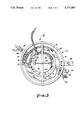
- FIG. 1 is a top perspective view of the mechanism of the present invention.
- FIG. 2 is a view taken along line 2--2 of FIG. 1.
- FIG. 3 is a sectional view taken along line 2--2 of FIG. 3.
- the mechanism 10 includes as one of its elements a container 12 having a first chamber 14 and a second chamber 16, FIG. 2.
- Container 12 includes a bottom portion 18 and an upwardly extending side portion 20, forming a generally cylindrical body.
- First chamber 14 is formed by a another container 22 having a bottom portion 24 and side wall portion 26 which extends upwardly.
- a circular spacer 28 separates bottom 18 of container 12 from bottom 24 of container 22.
- containers 12 and 24 may be integrally formed such that side wall portion 26 takes the form of a baffle within container 12.
- first chamber 14 is cylindrical while second chamber 16 is annular.
- First chamber 14 includes an outlet 28 and means 30 for dispersing or breaking any foam formed within first chamber 14. Means 30 is found at outlet 28 atop wall portion 26 of container 22.
- a cover 32 is employed to enclose container 12 and chambers 14 and 16.
- Means 34 is shown in FIG. 2 for supporting microbial matter 36 within chamber 14.
- Microbial matter may be a bacterium known as LLMO Gl in a solid or gel form, which is manufactured by General Environmental Science, of Beachwood, OH and available as LLMO Gl gel cube from Envirogenics of Carmel Valley, CA.
- the bacterial gel 36 includes a grease or fat consuming bacterium, as well as an activator and nutrient for the bacterium.
- Bacterial cake 36 has a volume of approximately 30 cubic inches and substitutes for approximately 200 gallons equivalent bacteria in a liquid medium.
- Bacterial cake or gel 36 is placed in a basket 38 which includes a plurality of openings 40.
- a bail 42 connects to the top portion of basket 38 and extends over a bar 44 which spans the inner top portion of container 12. Bail 42 is removable from basket 38 such that bacterial cake 36 is accessible.
- Means 42 provides water to first chamber 14.
- Means 42 includes a fitting 44 which connects to a municipal source of water through a hose or other conduit (not shown).
- Needle valve 46 regulates the flow of water into chamber 14 through tee fitting 48 having an antisyphon nipple 50.
- Conduit 52 extends into chamber 14 via elbow fitting 54 which passes through the wall of container 12.
- Fitting 56 serves as outlet from chamber 16 and lies below the level of outlet 28 of first chamber 14.
- Overflow draw 58 performs the function of a safety outlet from chamber 16.
- maintenance draw 60 includes a valve 62 which permits the draining of chamber 14 to a low level.
- Means 64 injects oxygen into first and second chambers 14 and 16.
- Means 64 is constructed with a diaphragm air pump 66 requiring a standard AC electrical source (not shown).
- Air conduits 66 and 68 extend to the bottom portions of chambers 14 and 16 and include spargers 70 and 72 to disperse the oxygen containing air throughout the liquids normally found in chambers 14 and 16.
- the user places bacterium cake 36 within basket 38 and supports basket 38 within chamber 14 of container 12 by the use of bail 42 and bar 44. Cover 32 is then placed atop container 44. Outlet 56 of second chamber 16 is connected to a drain leading into a grease trap or sump or into the sump directly. Needle valve 46 is then opened to control the rate of water entering first chamber 14, directional arrows 74 and 76, FIGS. 2 and 3. Air is then fed into container 12 by activating means 64 through the functioning of pump 66, FIGS. 1 and 2. Water slowly fills chamber 14 until reaching outlet 28. At this point the bacteria within chamber 14 has been activated by nutrients supplied either through bacterium cake 36 or through an external source.
- Bacteria entering chamber 16 passes or transports into a relatively nutrient-free environment and remains in chamber 16 until the water level in chamber 16 reaches outlet 56. At this point, the enzymes produced by the bacteria are particularly active. Such bacteria are then fed to a flow system such as a drain leading into a grease sump for use therein. It is believed that starving the bacteria of nutrients in chamber 16 activates enzyme production therein. It has been found that feeding the nutrient rich bacteria directly from first chamber 14 to the flow system decreases the effectiveness of the bacteria by 50%. Also, the flow rate determined by valve 46 is generally adjusted to coincide with the peak activation time associated with the bacterium found in the cake 36. In the present system it has been determined that approximately a rate of 6 gallons per day produces excellent results in the present embodiment.
- the bacterium maintains residence in first chamber 14 or approximately 12 hours and in second chamber 16 for approximately 12 hours.
- the sizes of chambers 14 and 16 as well as the rate of water and air fed into the same, may be adjusted according to the particular bacterium used in basket 38.
Abstract
Description
Claims (7)
Priority Applications (1)
| Application Number | Priority Date | Filing Date | Title |
|---|---|---|---|
| US07/580,032 US5171687A (en) | 1990-09-10 | 1990-09-10 | Apparatus for culturing and delivery of microbe for waste treatment in a flow system |
Applications Claiming Priority (1)
| Application Number | Priority Date | Filing Date | Title |
|---|---|---|---|
| US07/580,032 US5171687A (en) | 1990-09-10 | 1990-09-10 | Apparatus for culturing and delivery of microbe for waste treatment in a flow system |
Publications (1)
| Publication Number | Publication Date |
|---|---|
| US5171687A true US5171687A (en) | 1992-12-15 |
Family
ID=24319377
Family Applications (1)
| Application Number | Title | Priority Date | Filing Date |
|---|---|---|---|
| US07/580,032 Expired - Lifetime US5171687A (en) | 1990-09-10 | 1990-09-10 | Apparatus for culturing and delivery of microbe for waste treatment in a flow system |
Country Status (1)
| Country | Link |
|---|---|
| US (1) | US5171687A (en) |
Cited By (32)
| Publication number | Priority date | Publication date | Assignee | Title |
|---|---|---|---|---|
| US5516687A (en) * | 1994-04-08 | 1996-05-14 | Interbio, Inc. | Device and method for maintaining bacterial levels within an organic waste collection container |
| US5840182A (en) * | 1996-03-08 | 1998-11-24 | Brookhaven Science Associates Llc | Apparatus and method for biological purification of waste |
| US5866002A (en) * | 1992-03-24 | 1999-02-02 | Ivan William Yates | Apparatus for activation of a digesting agent and method of its use |
| US5877113A (en) * | 1997-12-12 | 1999-03-02 | Organica, Inc. | Solid form compositions for treating natural bodies of water |
| US5879932A (en) * | 1997-09-16 | 1999-03-09 | Van Erdewyk; Michael | Slow release microorganism dispenser |
| US5893975A (en) * | 1997-04-23 | 1999-04-13 | Roux Associates, Inc. | Enhanced subsurface flow constructed wetland |
| US5911877A (en) * | 1994-04-08 | 1999-06-15 | Interbio, Inc. | Device for maintaining bacterial levels within an organic waste collection container |
| US5925252A (en) * | 1997-12-03 | 1999-07-20 | Innovative Formulations | Water-dissolvable bioremediation device and method of use |
| WO2000011130A1 (en) * | 1998-08-24 | 2000-03-02 | Ophardt Product Gmbh & Co. Kg | Grease cleaning using grease solvents |
| US6087155A (en) * | 1998-01-14 | 2000-07-11 | York; Billy G. | On site microbial bioremediation system and method of using said system |
| US6210566B1 (en) | 1996-09-25 | 2001-04-03 | Joseph A. King | Nestable containers and improved water treatment materials |
| US6217892B1 (en) | 1997-10-24 | 2001-04-17 | Joseph A. King | Water treatment composition |
| US6383379B1 (en) * | 1997-10-06 | 2002-05-07 | Sk Chemicals | Method of preparing a microbial culture for wastewater treatment |
| US6395174B1 (en) * | 1997-10-07 | 2002-05-28 | Agrimond, L.L.C. | Method for lagoon remediation |
| US6402941B1 (en) | 2000-02-07 | 2002-06-11 | Wastewater Biological Solutions, Corp | Apparatus for biological treatment of environmental contaminants and waste |
| US20020164781A1 (en) * | 2001-05-02 | 2002-11-07 | Michael Alms | Compost tea system |
| US20020189997A1 (en) * | 2001-01-09 | 2002-12-19 | Jon Shaffer | Apparatus and method for biological treatment of environmental contaminants and waste |
| US20030136716A1 (en) * | 2002-01-18 | 2003-07-24 | Aquaresearch Canada Ltd./ Aquarecherche Canada Ltee | Growing and conditioning system for bioaugmentation products used for the treatment of waste water and water quality improvement |
| US20030159989A1 (en) * | 2002-02-28 | 2003-08-28 | Davis Tommy Mack | Method and apparatus for in-situ microbial seeding |
| US20040096963A1 (en) * | 2002-11-19 | 2004-05-20 | Hahn George E. | Apparatus for making a foliar liquid |
| KR100456231B1 (en) * | 2000-07-21 | 2004-11-08 | 김의수 | Machine for manufacturing of organic microorganism pharmaceutical |
| US20070175254A1 (en) * | 2006-02-01 | 2007-08-02 | Winslow Nathan E | Compost Tea Apparatus and Method |
| FR2898907A1 (en) * | 2006-03-27 | 2007-09-28 | Enrena Sarl | Bacterial culture process for obtaining culture with different bacterial strains using bioreactor consisting of receptor tubes serving as culture reservoir, where tubes are arranged vertically and connected with each other by joining tube |
| US20070272603A1 (en) * | 2003-11-04 | 2007-11-29 | Amano Enzyme Inc. | Treatment Apparatus of Waste Water Containing Oil and Fat for Grease Trap and Grease Trap |
| EP2001809A1 (en) * | 2006-03-07 | 2008-12-17 | Lemay, Denise | Integrated apparatus and system for the treatment of waste fluids and drain networks |
| US20090301964A1 (en) * | 2005-04-28 | 2009-12-10 | Takaichi Oya | Apparatus for treating oil- and fat-containing wastewater and method of treating oil- and fat-containing wastewater |
| US20100193430A1 (en) * | 1999-12-16 | 2010-08-05 | Robert Whiteman | Systems and methods for treating oil, fat and grease in collection systems |
| US9249036B2 (en) | 2012-01-11 | 2016-02-02 | In-Pipe Technology Company, Inc. | Modular smart biofeeding device |
| US20160120187A1 (en) * | 2014-10-30 | 2016-05-05 | George E. Hahn | Cartridge for foliar applications |
| US10322956B2 (en) | 1999-12-16 | 2019-06-18 | Advanced Biological Services, Inc. | Apparatus and methods for reducing nutrients in treating wastewater |
| US11155484B2 (en) | 2018-04-20 | 2021-10-26 | Advanced Biological Services, Inc. | Systems and methods for treating wastewater and providing class A sludge |
| US11685682B1 (en) * | 2020-02-28 | 2023-06-27 | Ian L. Roback | Systems and processes for removing pollutants from water, reducing greenhouse gas emissions, and reducing aquatic ecosystem destruction |
Citations (7)
| Publication number | Priority date | Publication date | Assignee | Title |
|---|---|---|---|---|
| US3145087A (en) * | 1961-05-22 | 1964-08-18 | Walker Alexander Marriott | Feeders for dissolving chemicals into intermittent flow fluid systems |
| US3864090A (en) * | 1973-10-12 | 1975-02-04 | Kenneth Richards | Pressure-type tablet hypochlorinating device |
| US4237003A (en) * | 1977-05-09 | 1980-12-02 | El Sayed Refaat M | Process for biological purification of liquid wastes |
| US4670149A (en) * | 1985-02-25 | 1987-06-02 | John Francis | Bacterial incubator and method of use |
| US4810385A (en) * | 1987-05-12 | 1989-03-07 | Sybron Chemicals, Inc. | Device for seeding bacterial cultures to systems to assist in biodegrading waste |
| US4882059A (en) * | 1987-11-25 | 1989-11-21 | General Environmental Science | Solubilization of organic materials in wastewater treatment |
| US4925564A (en) * | 1985-02-25 | 1990-05-15 | Robert B. Grubbs | Bacterial incubator and method of use |
-
1990
- 1990-09-10 US US07/580,032 patent/US5171687A/en not_active Expired - Lifetime
Patent Citations (7)
| Publication number | Priority date | Publication date | Assignee | Title |
|---|---|---|---|---|
| US3145087A (en) * | 1961-05-22 | 1964-08-18 | Walker Alexander Marriott | Feeders for dissolving chemicals into intermittent flow fluid systems |
| US3864090A (en) * | 1973-10-12 | 1975-02-04 | Kenneth Richards | Pressure-type tablet hypochlorinating device |
| US4237003A (en) * | 1977-05-09 | 1980-12-02 | El Sayed Refaat M | Process for biological purification of liquid wastes |
| US4670149A (en) * | 1985-02-25 | 1987-06-02 | John Francis | Bacterial incubator and method of use |
| US4925564A (en) * | 1985-02-25 | 1990-05-15 | Robert B. Grubbs | Bacterial incubator and method of use |
| US4810385A (en) * | 1987-05-12 | 1989-03-07 | Sybron Chemicals, Inc. | Device for seeding bacterial cultures to systems to assist in biodegrading waste |
| US4882059A (en) * | 1987-11-25 | 1989-11-21 | General Environmental Science | Solubilization of organic materials in wastewater treatment |
Non-Patent Citations (5)
| Title |
|---|
| Ecolab St. Paul, Minn. Biological Grease Digestant For Drains & Grease Traps. * |
| Ecolab-St. Paul, Minn.-Biological Grease Digestant For Drains & Grease Traps. |
| GES Brochure: Applied Biotechnology In Wastewater Treatment; The LLMO Systems. * |
| Roszak et al., Microbiol. Rev., 51, pp. 365 379, 1987. * |
| Roszak et al., Microbiol. Rev., 51, pp. 365-379, 1987. |
Cited By (54)
| Publication number | Priority date | Publication date | Assignee | Title |
|---|---|---|---|---|
| US5866002A (en) * | 1992-03-24 | 1999-02-02 | Ivan William Yates | Apparatus for activation of a digesting agent and method of its use |
| US5516687A (en) * | 1994-04-08 | 1996-05-14 | Interbio, Inc. | Device and method for maintaining bacterial levels within an organic waste collection container |
| US5911877A (en) * | 1994-04-08 | 1999-06-15 | Interbio, Inc. | Device for maintaining bacterial levels within an organic waste collection container |
| US6207056B1 (en) | 1996-03-08 | 2001-03-27 | Brookhaven Science Associates | Method for biological purification |
| US5840182A (en) * | 1996-03-08 | 1998-11-24 | Brookhaven Science Associates Llc | Apparatus and method for biological purification of waste |
| US6210566B1 (en) | 1996-09-25 | 2001-04-03 | Joseph A. King | Nestable containers and improved water treatment materials |
| US5893975A (en) * | 1997-04-23 | 1999-04-13 | Roux Associates, Inc. | Enhanced subsurface flow constructed wetland |
| US5879932A (en) * | 1997-09-16 | 1999-03-09 | Van Erdewyk; Michael | Slow release microorganism dispenser |
| US6383379B1 (en) * | 1997-10-06 | 2002-05-07 | Sk Chemicals | Method of preparing a microbial culture for wastewater treatment |
| US6554998B1 (en) * | 1997-10-07 | 2003-04-29 | Agrimond, Llc | Apparatus for lagoon remediation |
| US6599424B1 (en) * | 1997-10-07 | 2003-07-29 | Agrimond, Llc | Method for lagoon remediation |
| US6395174B1 (en) * | 1997-10-07 | 2002-05-28 | Agrimond, L.L.C. | Method for lagoon remediation |
| US6217892B1 (en) | 1997-10-24 | 2001-04-17 | Joseph A. King | Water treatment composition |
| US6248234B1 (en) * | 1997-12-03 | 2001-06-19 | Kenneth King Cline | Water-dissolvable bioremediation device and method of use |
| US5925252A (en) * | 1997-12-03 | 1999-07-20 | Innovative Formulations | Water-dissolvable bioremediation device and method of use |
| US5877113A (en) * | 1997-12-12 | 1999-03-02 | Organica, Inc. | Solid form compositions for treating natural bodies of water |
| US6087155A (en) * | 1998-01-14 | 2000-07-11 | York; Billy G. | On site microbial bioremediation system and method of using said system |
| WO2000011130A1 (en) * | 1998-08-24 | 2000-03-02 | Ophardt Product Gmbh & Co. Kg | Grease cleaning using grease solvents |
| US6706518B2 (en) | 1998-08-24 | 2004-03-16 | Ophardt Product Gmbh & Co. Kg | Clearing waste water pipes or grease traps clogged with grease with a grease solvent |
| US20100193430A1 (en) * | 1999-12-16 | 2010-08-05 | Robert Whiteman | Systems and methods for treating oil, fat and grease in collection systems |
| US9969633B2 (en) * | 1999-12-16 | 2018-05-15 | Robert Whiteman | Systems and methods for treating oil, fat and grease in collection systems |
| US10322956B2 (en) | 1999-12-16 | 2019-06-18 | Advanced Biological Services, Inc. | Apparatus and methods for reducing nutrients in treating wastewater |
| US6573085B2 (en) | 2000-02-07 | 2003-06-03 | Aqua-Norus®, Corp. | Composition for biological treatment of environmental contaminants and waste |
| US6488852B2 (en) * | 2000-02-07 | 2002-12-03 | Aqua-Novus™, Corp. | Apparatus and method for biological treatment of environmental contaminants and waste |
| US6402941B1 (en) | 2000-02-07 | 2002-06-11 | Wastewater Biological Solutions, Corp | Apparatus for biological treatment of environmental contaminants and waste |
| KR100456231B1 (en) * | 2000-07-21 | 2004-11-08 | 김의수 | Machine for manufacturing of organic microorganism pharmaceutical |
| US20030029793A1 (en) * | 2001-01-09 | 2003-02-13 | Jon Shaffer | Apparatus and method for biological treatment of environmental contaminants and waste |
| US20020189997A1 (en) * | 2001-01-09 | 2002-12-19 | Jon Shaffer | Apparatus and method for biological treatment of environmental contaminants and waste |
| US7022234B2 (en) | 2001-01-09 | 2006-04-04 | Aqua-Nova Llc | Method for biological treatment of environmental contaminants and waste |
| US20040232069A1 (en) * | 2001-01-09 | 2004-11-25 | Jon Shaffer | Apparatus and method for biological treatment of environmental contaminants and waste |
| US6649405B2 (en) * | 2001-05-02 | 2003-11-18 | Growing Solutions, Inc. | Compost tea system |
| US20020164781A1 (en) * | 2001-05-02 | 2002-11-07 | Michael Alms | Compost tea system |
| US20030136716A1 (en) * | 2002-01-18 | 2003-07-24 | Aquaresearch Canada Ltd./ Aquarecherche Canada Ltee | Growing and conditioning system for bioaugmentation products used for the treatment of waste water and water quality improvement |
| US20030159989A1 (en) * | 2002-02-28 | 2003-08-28 | Davis Tommy Mack | Method and apparatus for in-situ microbial seeding |
| US6878279B2 (en) | 2002-02-28 | 2005-04-12 | Tmd, L.L.C. | Method for in-situ microbial seeding |
| US20050211610A1 (en) * | 2002-02-28 | 2005-09-29 | Davis Tommy M | Apparatus for in-situ microbial seeding |
| US7132050B2 (en) * | 2002-02-28 | 2006-11-07 | Tmd, L.L.C. | Apparatus for in-situ microbial seeding |
| WO2004046014A3 (en) * | 2002-11-19 | 2004-12-09 | George E Hahn | Apparatus for making a foliar liquid |
| US6982167B2 (en) * | 2002-11-19 | 2006-01-03 | Hahn George E | Apparatus for making a foliar liquid |
| US20040096963A1 (en) * | 2002-11-19 | 2004-05-20 | Hahn George E. | Apparatus for making a foliar liquid |
| WO2004046014A2 (en) * | 2002-11-19 | 2004-06-03 | Hahn George E | Apparatus for making a foliar liquid |
| US20070272603A1 (en) * | 2003-11-04 | 2007-11-29 | Amano Enzyme Inc. | Treatment Apparatus of Waste Water Containing Oil and Fat for Grease Trap and Grease Trap |
| US7537690B2 (en) * | 2003-11-04 | 2009-05-26 | Amano Enzyme Inc. | Treatment apparatus of waste water containing oil and fat for grease trap and grease trap |
| US7828975B2 (en) * | 2005-04-28 | 2010-11-09 | Amano Enzyme Inc. | Apparatus for treating oil- and fat-containing wastewater and method of treating oil- and fat-containing wastewater |
| US20090301964A1 (en) * | 2005-04-28 | 2009-12-10 | Takaichi Oya | Apparatus for treating oil- and fat-containing wastewater and method of treating oil- and fat-containing wastewater |
| US9540290B2 (en) | 2006-02-01 | 2017-01-10 | Nathan E. Winslow | Compost tea apparatus |
| US20070175254A1 (en) * | 2006-02-01 | 2007-08-02 | Winslow Nathan E | Compost Tea Apparatus and Method |
| EP2001809A4 (en) * | 2006-03-07 | 2010-08-25 | Lemay Denise | Integrated apparatus and system for the treatment of waste fluids and drain networks |
| EP2001809A1 (en) * | 2006-03-07 | 2008-12-17 | Lemay, Denise | Integrated apparatus and system for the treatment of waste fluids and drain networks |
| FR2898907A1 (en) * | 2006-03-27 | 2007-09-28 | Enrena Sarl | Bacterial culture process for obtaining culture with different bacterial strains using bioreactor consisting of receptor tubes serving as culture reservoir, where tubes are arranged vertically and connected with each other by joining tube |
| US9249036B2 (en) | 2012-01-11 | 2016-02-02 | In-Pipe Technology Company, Inc. | Modular smart biofeeding device |
| US20160120187A1 (en) * | 2014-10-30 | 2016-05-05 | George E. Hahn | Cartridge for foliar applications |
| US11155484B2 (en) | 2018-04-20 | 2021-10-26 | Advanced Biological Services, Inc. | Systems and methods for treating wastewater and providing class A sludge |
| US11685682B1 (en) * | 2020-02-28 | 2023-06-27 | Ian L. Roback | Systems and processes for removing pollutants from water, reducing greenhouse gas emissions, and reducing aquatic ecosystem destruction |
Similar Documents
| Publication | Publication Date | Title |
|---|---|---|
| US5171687A (en) | Apparatus for culturing and delivery of microbe for waste treatment in a flow system | |
| US5609754A (en) | Secondary sewage treatment system | |
| US4994391A (en) | Bacteria culturing system | |
| US5549818A (en) | Sewage treatment system | |
| US7462285B2 (en) | Wastewater purification method and apparatus | |
| EP0897374A1 (en) | Apparatus and method for biological purification of wastes | |
| IL43710A (en) | Method and portable unit for converting toilet wastes to useable water | |
| WO1999018038A1 (en) | Installation for biochemichal sewage treatment | |
| US4919814A (en) | System and method for treating wastewater collected from septic tanks and similar installation | |
| US3864247A (en) | Biological decomposition of organic material by thermophilic microorganisms | |
| US20080251451A1 (en) | Method and Apparatus for the Aerobic Treatment of Waste | |
| JP3699570B2 (en) | Aerobic treatment method of sewage | |
| AU1136597A (en) | Fat and oil removal installation | |
| US6087155A (en) | On site microbial bioremediation system and method of using said system | |
| US4237003A (en) | Process for biological purification of liquid wastes | |
| US6270665B1 (en) | Aeration tank of organic waste liquor and aeration apparatus using the tank | |
| US5624563A (en) | Process and apparatus for an activated sludge treatment of wastewater | |
| EP0048148B1 (en) | Process of and digester for anaerobic treatment of waste water | |
| JPH11188376A (en) | Apparatus for treating oil and fat-containing waste water | |
| JPS6377595A (en) | Activated sludge treating device | |
| Trebler et al. | Fundamentals of the Control and Treatment of Dairy Waste | |
| JP2588151B2 (en) | Effective bacteria culture supply device | |
| CA2238729C (en) | Secondary sewage treatment system | |
| JP2007196105A (en) | Apparatus for treating wastewater such as dye wastewater | |
| CA2247871A1 (en) | Biological treatment of wastewater |
Legal Events
| Date | Code | Title | Description |
|---|---|---|---|
| FPAY | Fee payment |
Year of fee payment: 4 |
|
| REMI | Maintenance fee reminder mailed | ||
| FEPP | Fee payment procedure |
Free format text: PETITION RELATED TO MAINTENANCE FEES FILED (ORIGINAL EVENT CODE: PMFP); ENTITY STATUS OF PATENT OWNER: SMALL ENTITY |
|
| FEPP | Fee payment procedure |
Free format text: PETITION RELATED TO MAINTENANCE FEES GRANTED (ORIGINAL EVENT CODE: PMFG); ENTITY STATUS OF PATENT OWNER: SMALL ENTITY |
|
| FP | Lapsed due to failure to pay maintenance fee |
Effective date: 20001215 |
|
| FPAY | Fee payment |
Year of fee payment: 8 |
|
| SULP | Surcharge for late payment | ||
| STCF | Information on status: patent grant |
Free format text: PATENTED CASE |
|
| PRDP | Patent reinstated due to the acceptance of a late maintenance fee |
Effective date: 20010608 |
|
| REMI | Maintenance fee reminder mailed | ||
| FPAY | Fee payment |
Year of fee payment: 12 |
|
| SULP | Surcharge for late payment |
Year of fee payment: 11 |