US5172979A - Heater tube skin thermocouple - Google Patents
Heater tube skin thermocouple Download PDFInfo
- Publication number
- US5172979A US5172979A US07/800,319 US80031991A US5172979A US 5172979 A US5172979 A US 5172979A US 80031991 A US80031991 A US 80031991A US 5172979 A US5172979 A US 5172979A
- Authority
- US
- United States
- Prior art keywords
- thermocouple
- block
- skin
- assembly according
- shield
- Prior art date
- Legal status (The legal status is an assumption and is not a legal conclusion. Google has not performed a legal analysis and makes no representation as to the accuracy of the status listed.)
- Expired - Fee Related
Links
Images

Classifications
-
- G—PHYSICS
- G01—MEASURING; TESTING
- G01K—MEASURING TEMPERATURE; MEASURING QUANTITY OF HEAT; THERMALLY-SENSITIVE ELEMENTS NOT OTHERWISE PROVIDED FOR
- G01K1/00—Details of thermometers not specially adapted for particular types of thermometer
- G01K1/14—Supports; Fastening devices; Arrangements for mounting thermometers in particular locations
- G01K1/143—Supports; Fastening devices; Arrangements for mounting thermometers in particular locations for measuring surface temperatures
-
- H—ELECTRICITY
- H10—SEMICONDUCTOR DEVICES; ELECTRIC SOLID-STATE DEVICES NOT OTHERWISE PROVIDED FOR
- H10N—ELECTRIC SOLID-STATE DEVICES NOT OTHERWISE PROVIDED FOR
- H10N10/00—Thermoelectric devices comprising a junction of dissimilar materials, i.e. devices exhibiting Seebeck or Peltier effects
-
- H—ELECTRICITY
- H10—SEMICONDUCTOR DEVICES; ELECTRIC SOLID-STATE DEVICES NOT OTHERWISE PROVIDED FOR
- H10N—ELECTRIC SOLID-STATE DEVICES NOT OTHERWISE PROVIDED FOR
- H10N10/00—Thermoelectric devices comprising a junction of dissimilar materials, i.e. devices exhibiting Seebeck or Peltier effects
- H10N10/10—Thermoelectric devices comprising a junction of dissimilar materials, i.e. devices exhibiting Seebeck or Peltier effects operating with only the Peltier or Seebeck effects
- H10N10/17—Thermoelectric devices comprising a junction of dissimilar materials, i.e. devices exhibiting Seebeck or Peltier effects operating with only the Peltier or Seebeck effects characterised by the structure or configuration of the cell or thermocouple forming the device
Definitions
- the present invention relates to a skin thermocouple and in particular to a thermocouple providing improved diagnostic information on the operation of a heater.
- a skin thermocouple The basic purpose of a skin thermocouple is to protect a tube from overheating. An accurate skin thermocouple will also provide diagnostic information on the operation of the heater in which the tube is incorporated. All heaters which are susceptible to coke formation around the tubes should be provided with skin thermocouples. These types of heaters include all refinery heaters processing crude and heavier feed stocks. Also, heaters operating with tube wall temperatures near the maximum permissible temperature of the tube should be equipped with skin thermocouples.
- the skin thermocouple is preferably located at the point of highest temperature on the tube for the obvious reason that this is the point where damage is most likely to occur.
- a good skin thermocouple must not only measure the temperature of the tube metal accurately, but also have a life span which is substantially equal to the turnaround time of the units, which time is usually in excess of two years.
- the prior art is represented by U.S. Pat. No. 3,015,234 to Springfield; U.S. Pat. No. 3,263,502 to Springfield; U.S. Pat. No. 3,901,080 to Hilborn; and U.S. Pat. No. 4,625,200 to Hilborn.
- the first Springfield reference shows means for mounting a bimetallic heat sensing member in a heater chamber, such as a pressure vessel.
- the second Springfield reference concerns means for mounting multiple thermocouples into a device to be temperature measured.
- the first Hilborn reference considers the problems of mounting a skin temperature measuring device on a curved surface and includes a shield to protect the thermocouple junction.
- the second Hilborn reference relates to positioning a thermocouple cable in such a manner as to detect hot spots within an area to be measured. None of these references addresses the specific problem solved by the present invention.
- the subject skin thermocouple assembly forms a metal path along the tube wall without any gaps and/or scale resistance.
- a thermocouple mounting block is welded to the hottest location on the tube which normally is the side closest to the flame or hot gas cavity and the leads take the shortest route away from this area.
- An outer radiation shield is provided over the thermocouple junction to prevent the block from being subject to direct radiation which would adversely affect temperature measurement by the thermocouple.
- a insulation pad is placed between the outer shield and the mounting block so that outer shield does not act as a fin to radiate heat to or from the thermocouple.
- the thermocouple leads are insulated and shielded in the hottest zone of the tube.
- FIG. 1 is a partial transverse section through a tube coil with the subject invention mounted thereon;
- FIG. 2 is a perspective view of a section of tube coil with the subject invention mounted thereon with the covers removed;
- FIG. 3 is a view similar to FIG. 2 showing the present invention with the covers in place;
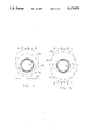
- FIG. 4 is a diagrammatic view showing distribution from single side firing.
- FIG. 5 is a diagrammatic view showing flux distribution from double side firing.
- the subject skin thermocouple assembly 10 is shown mounted on a heater tube 12.
- the skin thermocouple assembly 10 includes a known thermocouple 14 which has a pair of elongated members 16,18 encased within a sheath lead 20.
- One free end of the thermocouple 14 is mounted in a block 22, here shown with a trapezoidal section for reasons which will be described later.
- a bore 24 passes through the block 22 adjacent one surface thereof, which surface is welded to the tube 12 at 26.
- the mounting block 22 has a pair of studs 28,30 projecting from the outer surface 32 thereof.
- the heat shield 34 (FIGS. 1 and 3) is profiled to enclose the block 20 and a portion of the lead 20.
- the heatshield 34 has a top wall 36 with depending side walls 38,40 and an end wall (not shown) and encloses a layer of insulation 42.
- the thermocouple lead 20 is profiled with a first bend at 44, then is bent in an arc to follow the curvature of the tube until it reaches a point away from the hot zone where a second bend 46 directs the lead longitudinally along the tube.
- the reason for this configuration is that the thermocouple is mounted on the tube at the point of highest temperature, but it is desired that the thermocouple lead not be exposed to this temperature for its entire length. Therefore, the thermocouple lead is bent to get it out of the high temperature are to a shaded side of the tube where it will be less affected by the heat being applied to the tube.
- thermocouple 14 is passed through the bore 24 in the thermocouple block 22 such that its measuring head or free end extends within the short distance from the front edge of the block 22. It is preferably shop-welded to the block 22 and the bottom of the block is ground to match the curved surface of the tube 12. The marginal edges of the block 22 are welded along the longitudinal axis of the tube 12 at 26 to minimize gaping. Studs 28,30 are shop-fastened to the back of the block 22 to receive the heat shield 34 thereon.
- thermocouple lead 20 after an initial short straight run, is bent 30° at 44 and, at a point of inflection, a second bend 46 is made.
- the second bend is 60° to direct the sheathed lead towards the wall.
- the second bend is a reversed 30° which places the lead into a cool zone.
- the lead is held in place against the tube by welding on clips 48 at spaced intervals.
- FIG. 4 shows the theoretical flux profile around a single heater tube 12 adjacent to a wall 52 of a radiant chamber (none of these known items being shown) having an adjacent tube on each side.
- the former is a result of direct radiation from flame-hot gas cavity in the front of the tube and the latter is re-radiated from the near adiabatic refractory wall (not shown) to the backside of the tube. There is some overlapping of these flux fields.
- each flux field and their combined magnitude is proportional to the distance to the envelope edge minus the outside diameter of the tube.
- the average flux 58 is illustrated by the dashed circle in the figure.
- the vicinity of the leading edge of the flux profile is relatively flat whereas it rapidly decreases from approximately the 2 o'clock point onwards. This is due to shading by the adjacent tube.
- the hottest location is at the 12 o'clock point and fixes the location of the thermocouple junction. At the 3 or 9 o'clock point the flux is 40% of the peak flux.
- Double side firing is the condition where the tube coil is spaced from the furnace walls and burners are located on both sides of the coil.
- An analysis of FIG. 5 shows the double fired tube with incident flux 60 and 62 and average flux 64. It will be noted that at 90° the flux is 61% of the peak flux and is the coolest surface on the tube.
- An important objective of this invention is to protect the skin thermocouple leads from exposure to radiation from flame and hot gases until they reach this cool section of the tube where they are protected by adjacent tube shading.
- the heat shield 34 over block 22 used with the present invention is insulated on the inside and does not touch the subject thermal coil nor is it welded to the tube surface.
- the heat shield 50 is filled with an insulation material and is also provided to cover a portion of the thermocouple lead. Notches are cut in the shield 50 to allow it to be configured to the tube. It is fastened to the tube surface by tack-welds between the notches. The space between the notches is also provided for clearance for relative movement between the tube and the shield.
- the skin thermocouple junction is located at the highest temperature point on the circumference of the tube. There is no heat leak due to a circumferential component of conductive heat transfer through the thermal block.
- the insulated thermocouple shield completely shades the block from direct radiant heat transfer from the flame or hot gases within the hot cavity and indirectly by re-radiating from the hot inner surface of the shield.
- the shield is not welded to the tube and thus it will not act as a fin which would result in other than true temperature readings.
- the insulated lead cover protects the leads from reaching the temperature of the hot combustion gasses, which is a common cause of failure of thermocouples.
- the use of the 30° and 60° bends, rather than 90° bends, further reduces the stress created on the thermocouple leads. Such stresses promote the formation of large grain structure and also are a common cause of short thermocouple life.
Abstract
Description
Claims (10)
Priority Applications (1)
| Application Number | Priority Date | Filing Date | Title |
|---|---|---|---|
| US07/800,319 US5172979A (en) | 1991-11-29 | 1991-11-29 | Heater tube skin thermocouple |
Applications Claiming Priority (1)
| Application Number | Priority Date | Filing Date | Title |
|---|---|---|---|
| US07/800,319 US5172979A (en) | 1991-11-29 | 1991-11-29 | Heater tube skin thermocouple |
Publications (1)
| Publication Number | Publication Date |
|---|---|
| US5172979A true US5172979A (en) | 1992-12-22 |
Family
ID=25178092
Family Applications (1)
| Application Number | Title | Priority Date | Filing Date |
|---|---|---|---|
| US07/800,319 Expired - Fee Related US5172979A (en) | 1991-11-29 | 1991-11-29 | Heater tube skin thermocouple |
Country Status (1)
| Country | Link |
|---|---|
| US (1) | US5172979A (en) |
Cited By (39)
| Publication number | Priority date | Publication date | Assignee | Title |
|---|---|---|---|---|
| US5249864A (en) * | 1992-10-23 | 1993-10-05 | Gas Research Institute | System for characterizing temperature of fluids |
| US5271675A (en) * | 1992-10-22 | 1993-12-21 | Gas Research Institute | System for characterizing pressure, movement, temperature and flow pattern of fluids |
| US5454641A (en) * | 1994-01-13 | 1995-10-03 | Ranco Incorporated Of Delaware | Temperature transducer assembly |
| FR2737008A1 (en) * | 1995-07-18 | 1997-01-24 | Dieterlen Dominique | Surface temperature probe for fluid container - has body with flat surface presenting hole which houses temperature sensor connected to signal collecting conductors while hole is filled with protecting resin |
| US5707151A (en) * | 1994-01-13 | 1998-01-13 | Ranco Incorporated Of Delaware | Temperature transducer assembly |
| US5993061A (en) * | 1995-07-18 | 1999-11-30 | Elf Antar France | Device for measuring the temperature of a hot wall |
| US6113263A (en) * | 1997-05-14 | 2000-09-05 | Anritsu Meter Co., Ltd. | Contact-type thermometer |
| US6127766A (en) * | 1998-05-04 | 2000-10-03 | Siemens Westinghouse Power Corporation | Paired-tube thermoelectric couple |
| WO2000058702A1 (en) * | 1999-03-29 | 2000-10-05 | Palti Yoram Prof | Non-invasive temperature measurement method and apparatus |
| US6158886A (en) * | 1997-10-15 | 2000-12-12 | Gay Engineering & Sales Company, Inc. | Heat shield with moldable insulation |
| US6334707B1 (en) * | 2000-07-19 | 2002-01-01 | Second Source Supply Incorporated | Temperature sensing device for test cylinder |
| US6536950B1 (en) | 1999-10-13 | 2003-03-25 | Texaco Inc. | Sapphire reinforced thermocouple protection tube |
| US6541737B1 (en) * | 1998-11-11 | 2003-04-01 | Daimlerchrysler Ag | Temperature detector for an air-conditioned vehicle seat |
| US6558036B2 (en) * | 2000-11-29 | 2003-05-06 | Weatherford/Lamb, Inc. | Non-intrusive temperature sensor for measuring internal temperature of fluids within pipes |
| DE10255441B3 (en) * | 2002-11-28 | 2004-04-08 | Daimlerchrysler Ag | Heated passenger seat for automobile has temperature sensor protected from heat radiation for detecting actual temperature of seating surface |
| US6761480B2 (en) | 2002-08-26 | 2004-07-13 | Charles William Parnicza | Thermocouple holder for furnace tube |
| US20040255666A1 (en) * | 2003-06-19 | 2004-12-23 | Ametek, Inc. | Thermocouple device and method of thermocouple construction employing small grain size conductors |
| US20050217841A1 (en) * | 2002-10-16 | 2005-10-06 | Clyde Bergemann Gmbh | Heat flux measuring device for pressure pipes, method for producing a measuring device, method for monitoring an operating state of a heat exchanger, heat exchanger and method for measuring a heat flux |
| US7036983B2 (en) | 1998-06-26 | 2006-05-02 | General Electric Company | Thermocouple for use in gasification process |
| US20070153872A1 (en) * | 2005-12-30 | 2007-07-05 | Hon Hai Precision Industry Co., Ltd. | Device for measuring temperature of heat pipe |
| US20070237202A1 (en) * | 2006-04-07 | 2007-10-11 | Jaffe Limited | Method for measuring temperature of heat pipe |
| US20080008227A1 (en) * | 2006-07-10 | 2008-01-10 | Samsung Electronics Co., Ltd. | Temperature sensor fixing apparatus and air conditioner having the same |
| US20080163692A1 (en) * | 2007-01-09 | 2008-07-10 | Schlumberger Technology Corporation | System and method for using one or more thermal sensor probes for flow analysis, flow assurance and pipe condition monitoring of a pipeline for flowing hydrocarbons |
| DE102009026402A1 (en) | 2008-11-19 | 2010-05-20 | Endress + Hauser Wetzer Gmbh + Co. Kg | Device for determining and / or monitoring a process variable |
| US8226294B2 (en) | 2009-08-31 | 2012-07-24 | Arizant Healthcare Inc. | Flexible deep tissue temperature measurement devices |
| US8292502B2 (en) | 2010-04-07 | 2012-10-23 | Arizant Healthcare Inc. | Constructions for zero-heat-flux, deep tissue temperature measurement devices |
| US8292495B2 (en) | 2010-04-07 | 2012-10-23 | Arizant Healthcare Inc. | Zero-heat-flux, deep tissue temperature measurement devices with thermal sensor calibration |
| US20130070808A1 (en) * | 2011-09-15 | 2013-03-21 | Jeffrey N. Daily | Temperature sensing assembly for measuring temperature of a surface of a structure |
| KR101404609B1 (en) * | 2014-01-22 | 2014-06-09 | (주)두광엠에프지 | Thermocouples assembly for tube skin |
| CN104475912A (en) * | 2014-11-27 | 2015-04-01 | 国核(北京)科学技术研究院有限公司 | Armored thermocouple auxiliary welding device and welding method |
| US9068895B2 (en) | 2009-04-15 | 2015-06-30 | 3M Innovative Properties Company | Deep tissue temperature probe constructions |
| US9310257B2 (en) | 2009-04-15 | 2016-04-12 | 3M Innovative Properties Company | Deep tissue temperature probe constructions |
| US9354122B2 (en) | 2011-05-10 | 2016-05-31 | 3M Innovative Properties Company | Zero-heat-flux, deep tissue temperature measurement system |
| US20170023415A1 (en) * | 2015-07-23 | 2017-01-26 | Abb Schweiz Ag | Surface temperature probe |
| CN109855747A (en) * | 2017-11-30 | 2019-06-07 | 苏州长风航空电子有限公司 | It is a kind of based on be welded and fixed measurement superhigh temperature titanium alloy wall temperature sensor |
| US20190234804A1 (en) * | 2016-09-09 | 2019-08-01 | Okazaki Manufacturing Company | Pad-equipped thermocouple and method for producing sheath thermocouple used therein |
| US20200393306A1 (en) * | 2018-08-02 | 2020-12-17 | Shibaura Electronics Co., Ltd. | Temperature detection device and assembly thereof |
| US20210396594A1 (en) * | 2018-10-04 | 2021-12-23 | Endress+Hauser Wetzer Gmbh+Co. Kg | Skin-point temperature measurement assembly |
| US11408779B2 (en) | 2019-06-03 | 2022-08-09 | Daily Thermetrics Corporation | Temperature sensor and methods of use |
Citations (10)
| Publication number | Priority date | Publication date | Assignee | Title |
|---|---|---|---|---|
| US2142677A (en) * | 1935-10-30 | 1939-01-03 | Schweitzer & Conrad Inc | Temperature indicator |
| US3015234A (en) * | 1958-04-14 | 1962-01-02 | Gay Sales Co | Bimetallic mounting |
| US3143439A (en) * | 1961-10-11 | 1964-08-04 | American Radiator & Standard | Surface thermocouple assembly |
| US3263502A (en) * | 1964-01-21 | 1966-08-02 | Redwood L Springfield | Multiple thermocouple support |
| US3874239A (en) * | 1974-03-04 | 1975-04-01 | Thermo Couple Prod Co | Surface thermocouple |
| US3901080A (en) * | 1972-06-02 | 1975-08-26 | William Dwight Hilborn | Temperature measuring device |
| US3907606A (en) * | 1974-01-25 | 1975-09-23 | Sun Oil Co Pennsylvania | Heat shield for temperature sensors |
| GB2062860A (en) * | 1979-11-06 | 1981-05-28 | Iss Clorius Ltd | Temperature sensing assembly |
| SU1040351A1 (en) * | 1980-07-04 | 1983-09-07 | Специальное конструкторское бюро "Газприборавтоматика" Всесоюзного научно-производственного объединения "Союзгазавтоматика" | Device for measuring temperature primarily of pipe line underground part |
| US4625200A (en) * | 1985-01-10 | 1986-11-25 | Gay Engineering & Sales Co., Inc. | Heat detection system |
-
1991
- 1991-11-29 US US07/800,319 patent/US5172979A/en not_active Expired - Fee Related
Patent Citations (10)
| Publication number | Priority date | Publication date | Assignee | Title |
|---|---|---|---|---|
| US2142677A (en) * | 1935-10-30 | 1939-01-03 | Schweitzer & Conrad Inc | Temperature indicator |
| US3015234A (en) * | 1958-04-14 | 1962-01-02 | Gay Sales Co | Bimetallic mounting |
| US3143439A (en) * | 1961-10-11 | 1964-08-04 | American Radiator & Standard | Surface thermocouple assembly |
| US3263502A (en) * | 1964-01-21 | 1966-08-02 | Redwood L Springfield | Multiple thermocouple support |
| US3901080A (en) * | 1972-06-02 | 1975-08-26 | William Dwight Hilborn | Temperature measuring device |
| US3907606A (en) * | 1974-01-25 | 1975-09-23 | Sun Oil Co Pennsylvania | Heat shield for temperature sensors |
| US3874239A (en) * | 1974-03-04 | 1975-04-01 | Thermo Couple Prod Co | Surface thermocouple |
| GB2062860A (en) * | 1979-11-06 | 1981-05-28 | Iss Clorius Ltd | Temperature sensing assembly |
| SU1040351A1 (en) * | 1980-07-04 | 1983-09-07 | Специальное конструкторское бюро "Газприборавтоматика" Всесоюзного научно-производственного объединения "Союзгазавтоматика" | Device for measuring temperature primarily of pipe line underground part |
| US4625200A (en) * | 1985-01-10 | 1986-11-25 | Gay Engineering & Sales Co., Inc. | Heat detection system |
Cited By (56)
| Publication number | Priority date | Publication date | Assignee | Title |
|---|---|---|---|---|
| US5271675A (en) * | 1992-10-22 | 1993-12-21 | Gas Research Institute | System for characterizing pressure, movement, temperature and flow pattern of fluids |
| US5326969A (en) * | 1992-10-22 | 1994-07-05 | Gas Research Institute | System for characterizing flow pattern and pressure of a fluid |
| US5488224A (en) * | 1992-10-22 | 1996-01-30 | Gas Research Institute | System for characterizing flow pattern, pressure and movement of a fluid |
| US5249864A (en) * | 1992-10-23 | 1993-10-05 | Gas Research Institute | System for characterizing temperature of fluids |
| US5454641A (en) * | 1994-01-13 | 1995-10-03 | Ranco Incorporated Of Delaware | Temperature transducer assembly |
| US5707151A (en) * | 1994-01-13 | 1998-01-13 | Ranco Incorporated Of Delaware | Temperature transducer assembly |
| FR2737008A1 (en) * | 1995-07-18 | 1997-01-24 | Dieterlen Dominique | Surface temperature probe for fluid container - has body with flat surface presenting hole which houses temperature sensor connected to signal collecting conductors while hole is filled with protecting resin |
| US5993061A (en) * | 1995-07-18 | 1999-11-30 | Elf Antar France | Device for measuring the temperature of a hot wall |
| US6113263A (en) * | 1997-05-14 | 2000-09-05 | Anritsu Meter Co., Ltd. | Contact-type thermometer |
| US6158886A (en) * | 1997-10-15 | 2000-12-12 | Gay Engineering & Sales Company, Inc. | Heat shield with moldable insulation |
| US6127766A (en) * | 1998-05-04 | 2000-10-03 | Siemens Westinghouse Power Corporation | Paired-tube thermoelectric couple |
| US7036983B2 (en) | 1998-06-26 | 2006-05-02 | General Electric Company | Thermocouple for use in gasification process |
| US6541737B1 (en) * | 1998-11-11 | 2003-04-01 | Daimlerchrysler Ag | Temperature detector for an air-conditioned vehicle seat |
| US6220750B1 (en) * | 1999-03-29 | 2001-04-24 | Yoram Palti | Non-invasive temperature measurement method and apparatus |
| WO2000058702A1 (en) * | 1999-03-29 | 2000-10-05 | Palti Yoram Prof | Non-invasive temperature measurement method and apparatus |
| US6536950B1 (en) | 1999-10-13 | 2003-03-25 | Texaco Inc. | Sapphire reinforced thermocouple protection tube |
| US6334707B1 (en) * | 2000-07-19 | 2002-01-01 | Second Source Supply Incorporated | Temperature sensing device for test cylinder |
| US6558036B2 (en) * | 2000-11-29 | 2003-05-06 | Weatherford/Lamb, Inc. | Non-intrusive temperature sensor for measuring internal temperature of fluids within pipes |
| US6761480B2 (en) | 2002-08-26 | 2004-07-13 | Charles William Parnicza | Thermocouple holder for furnace tube |
| US20050217841A1 (en) * | 2002-10-16 | 2005-10-06 | Clyde Bergemann Gmbh | Heat flux measuring device for pressure pipes, method for producing a measuring device, method for monitoring an operating state of a heat exchanger, heat exchanger and method for measuring a heat flux |
| US7249885B2 (en) * | 2002-10-16 | 2007-07-31 | Clyde Bergemann Gmbh | Heat flux measuring device for pressure pipes, method for producing a measuring device, method for monitoring an operating state of a heat exchanger, heat exchanger and method for measuring a heat flux |
| DE10255441B3 (en) * | 2002-11-28 | 2004-04-08 | Daimlerchrysler Ag | Heated passenger seat for automobile has temperature sensor protected from heat radiation for detecting actual temperature of seating surface |
| US20040255666A1 (en) * | 2003-06-19 | 2004-12-23 | Ametek, Inc. | Thermocouple device and method of thermocouple construction employing small grain size conductors |
| US20070153872A1 (en) * | 2005-12-30 | 2007-07-05 | Hon Hai Precision Industry Co., Ltd. | Device for measuring temperature of heat pipe |
| US7543983B2 (en) * | 2005-12-30 | 2009-06-09 | Hon Hai Precision Industry Co., Ltd. | Device for measuring temperature of heat pipe |
| US20070237202A1 (en) * | 2006-04-07 | 2007-10-11 | Jaffe Limited | Method for measuring temperature of heat pipe |
| US20080008227A1 (en) * | 2006-07-10 | 2008-01-10 | Samsung Electronics Co., Ltd. | Temperature sensor fixing apparatus and air conditioner having the same |
| US8360635B2 (en) * | 2007-01-09 | 2013-01-29 | Schlumberger Technology Corporation | System and method for using one or more thermal sensor probes for flow analysis, flow assurance and pipe condition monitoring of a pipeline for flowing hydrocarbons |
| US20080163692A1 (en) * | 2007-01-09 | 2008-07-10 | Schlumberger Technology Corporation | System and method for using one or more thermal sensor probes for flow analysis, flow assurance and pipe condition monitoring of a pipeline for flowing hydrocarbons |
| DE102009026402A1 (en) | 2008-11-19 | 2010-05-20 | Endress + Hauser Wetzer Gmbh + Co. Kg | Device for determining and / or monitoring a process variable |
| DE102009026402B4 (en) | 2008-11-19 | 2023-11-02 | Endress + Hauser Wetzer Gmbh + Co. Kg | Device for determining and/or monitoring a process variable |
| US9068895B2 (en) | 2009-04-15 | 2015-06-30 | 3M Innovative Properties Company | Deep tissue temperature probe constructions |
| US9310257B2 (en) | 2009-04-15 | 2016-04-12 | 3M Innovative Properties Company | Deep tissue temperature probe constructions |
| US8226294B2 (en) | 2009-08-31 | 2012-07-24 | Arizant Healthcare Inc. | Flexible deep tissue temperature measurement devices |
| US8801282B2 (en) | 2010-04-07 | 2014-08-12 | 3M Innovative Properties Company | Constructions for zero-heat-flux, deep tissue temperature measurement devices |
| US8801272B2 (en) | 2010-04-07 | 2014-08-12 | 3M Innovative Properties Company | Zero-heat-flux, deep tissue temperature measurement devices with thermal sensor calibration |
| US8292502B2 (en) | 2010-04-07 | 2012-10-23 | Arizant Healthcare Inc. | Constructions for zero-heat-flux, deep tissue temperature measurement devices |
| US8292495B2 (en) | 2010-04-07 | 2012-10-23 | Arizant Healthcare Inc. | Zero-heat-flux, deep tissue temperature measurement devices with thermal sensor calibration |
| US10274383B2 (en) | 2011-05-10 | 2019-04-30 | 3M Innovative Properties Company | Zero-heat-flux, deep tissue temperature measurement system |
| US9354122B2 (en) | 2011-05-10 | 2016-05-31 | 3M Innovative Properties Company | Zero-heat-flux, deep tissue temperature measurement system |
| US8870455B2 (en) * | 2011-09-15 | 2014-10-28 | Jeffrey N. Daily | Temperature sensing assembly for measuring temperature of a surface of a structure |
| US20130070808A1 (en) * | 2011-09-15 | 2013-03-21 | Jeffrey N. Daily | Temperature sensing assembly for measuring temperature of a surface of a structure |
| US9752937B2 (en) | 2011-09-15 | 2017-09-05 | Jeffrey N. Daily | Temperature sensing assembly for measuring temperature of a surface of a structure |
| KR101404609B1 (en) * | 2014-01-22 | 2014-06-09 | (주)두광엠에프지 | Thermocouples assembly for tube skin |
| CN104475912A (en) * | 2014-11-27 | 2015-04-01 | 国核(北京)科学技术研究院有限公司 | Armored thermocouple auxiliary welding device and welding method |
| US20170023415A1 (en) * | 2015-07-23 | 2017-01-26 | Abb Schweiz Ag | Surface temperature probe |
| US10190917B2 (en) * | 2015-07-23 | 2019-01-29 | Abb Schweiz Ag | Surface temperature probe |
| US20190234804A1 (en) * | 2016-09-09 | 2019-08-01 | Okazaki Manufacturing Company | Pad-equipped thermocouple and method for producing sheath thermocouple used therein |
| US10481010B2 (en) * | 2016-09-09 | 2019-11-19 | Okazaki Manufacturing Company | Pad-equipped thermocouple and method for producing sheath thermocouple used therein |
| CN109855747A (en) * | 2017-11-30 | 2019-06-07 | 苏州长风航空电子有限公司 | It is a kind of based on be welded and fixed measurement superhigh temperature titanium alloy wall temperature sensor |
| US20200393306A1 (en) * | 2018-08-02 | 2020-12-17 | Shibaura Electronics Co., Ltd. | Temperature detection device and assembly thereof |
| US11892358B2 (en) * | 2018-08-02 | 2024-02-06 | Shibaura Electronics Co., Ltd. | Temperature detection device and assembly thereof |
| US20210396594A1 (en) * | 2018-10-04 | 2021-12-23 | Endress+Hauser Wetzer Gmbh+Co. Kg | Skin-point temperature measurement assembly |
| US11841277B2 (en) * | 2018-10-04 | 2023-12-12 | Endress+Hauser Wetzer Gmbh+Co. Kg | Skin-point temperature measurement assembly |
| US11408779B2 (en) | 2019-06-03 | 2022-08-09 | Daily Thermetrics Corporation | Temperature sensor and methods of use |
| US11747214B2 (en) | 2019-06-03 | 2023-09-05 | Daily Thermetrics Corporation | Temperature sensor and methods of use |
Similar Documents
| Publication | Publication Date | Title |
|---|---|---|
| US5172979A (en) | Heater tube skin thermocouple | |
| CA1104725A (en) | Tube skin thermocouples and method of making same | |
| US3907606A (en) | Heat shield for temperature sensors | |
| US8353627B2 (en) | Temperature sensor for burner, and burner | |
| EP0135250B1 (en) | Thermocouple, method of making it and mounting it on a tube | |
| US3939554A (en) | Surface thermocouple | |
| US4043200A (en) | Surface thermocouple | |
| TWI641782B (en) | Boiler | |
| US3901080A (en) | Temperature measuring device | |
| US4038105A (en) | Radiation shields for aspirating pyrometers | |
| JPH0693345A (en) | Method for heat treatment and device for controlling temperature | |
| JP2007024830A (en) | Attaching structure of surface thermometer | |
| CA1141987A (en) | Surface thermocouple assembly and method of making same | |
| US2048681A (en) | Thermocouple shield | |
| US4162175A (en) | Temperature sensors | |
| JP2786811B2 (en) | Temperature measurement method | |
| JP7439050B2 (en) | low profile surface temperature sensor | |
| JPS59204731A (en) | Thermometer for high-temperature, high-pressure air flow | |
| JPS6145462Y2 (en) | ||
| JPS6145463Y2 (en) | ||
| CN105890790B (en) | A kind of thermal protection struc ture temp measuring method of temperature formula distribution in gradient | |
| JPH0691286B2 (en) | Thermocouple assembly | |
| US4502792A (en) | Apparatus for calibrating a pyrometer | |
| JP6844305B2 (en) | Temperature measuring device | |
| KR20020052869A (en) | Shunt error free sheathed thermocouple |
Legal Events
| Date | Code | Title | Description |
|---|---|---|---|
| AS | Assignment |
Owner name: TEXAS INC. A CORPORATION OF DELAWARE Free format text: ASSIGNMENT OF ASSIGNORS INTEREST.;ASSIGNORS:BARKLEY, RICH W.;LEUNG, KEN C.;LOFTUS, JORDAN;REEL/FRAME:005932/0672 Effective date: 19911125 |
|
| FEPP | Fee payment procedure |
Free format text: PAYOR NUMBER ASSIGNED (ORIGINAL EVENT CODE: ASPN); ENTITY STATUS OF PATENT OWNER: LARGE ENTITY |
|
| FPAY | Fee payment |
Year of fee payment: 4 |
|
| FPAY | Fee payment |
Year of fee payment: 8 |
|
| REMI | Maintenance fee reminder mailed | ||
| LAPS | Lapse for failure to pay maintenance fees | ||
| STCH | Information on status: patent discontinuation |
Free format text: PATENT EXPIRED DUE TO NONPAYMENT OF MAINTENANCE FEES UNDER 37 CFR 1.362 |
|
| FP | Lapsed due to failure to pay maintenance fee |
Effective date: 20041222 |