US5181556A - System for substrate cooling in an evacuated environment - Google Patents
System for substrate cooling in an evacuated environment Download PDFInfo
- Publication number
- US5181556A US5181556A US07/763,355 US76335591A US5181556A US 5181556 A US5181556 A US 5181556A US 76335591 A US76335591 A US 76335591A US 5181556 A US5181556 A US 5181556A
- Authority
- US
- United States
- Prior art keywords
- heat sinks
- article
- substrate
- cooling
- heat
- Prior art date
- Legal status (The legal status is an assumption and is not a legal conclusion. Google has not performed a legal analysis and makes no representation as to the accuracy of the status listed.)
- Expired - Lifetime
Links
Images


Classifications
-
- B—PERFORMING OPERATIONS; TRANSPORTING
- B01—PHYSICAL OR CHEMICAL PROCESSES OR APPARATUS IN GENERAL
- B01J—CHEMICAL OR PHYSICAL PROCESSES, e.g. CATALYSIS OR COLLOID CHEMISTRY; THEIR RELEVANT APPARATUS
- B01J3/00—Processes of utilising sub-atmospheric or super-atmospheric pressure to effect chemical or physical change of matter; Apparatus therefor
- B01J3/006—Processes utilising sub-atmospheric pressure; Apparatus therefor
-
- C—CHEMISTRY; METALLURGY
- C23—COATING METALLIC MATERIAL; COATING MATERIAL WITH METALLIC MATERIAL; CHEMICAL SURFACE TREATMENT; DIFFUSION TREATMENT OF METALLIC MATERIAL; COATING BY VACUUM EVAPORATION, BY SPUTTERING, BY ION IMPLANTATION OR BY CHEMICAL VAPOUR DEPOSITION, IN GENERAL; INHIBITING CORROSION OF METALLIC MATERIAL OR INCRUSTATION IN GENERAL
- C23C—COATING METALLIC MATERIAL; COATING MATERIAL WITH METALLIC MATERIAL; SURFACE TREATMENT OF METALLIC MATERIAL BY DIFFUSION INTO THE SURFACE, BY CHEMICAL CONVERSION OR SUBSTITUTION; COATING BY VACUUM EVAPORATION, BY SPUTTERING, BY ION IMPLANTATION OR BY CHEMICAL VAPOUR DEPOSITION, IN GENERAL
- C23C14/00—Coating by vacuum evaporation, by sputtering or by ion implantation of the coating forming material
- C23C14/22—Coating by vacuum evaporation, by sputtering or by ion implantation of the coating forming material characterised by the process of coating
- C23C14/54—Controlling or regulating the coating process
- C23C14/541—Heating or cooling of the substrates
-
- G—PHYSICS
- G05—CONTROLLING; REGULATING
- G05D—SYSTEMS FOR CONTROLLING OR REGULATING NON-ELECTRIC VARIABLES
- G05D23/00—Control of temperature
- G05D23/19—Control of temperature characterised by the use of electric means
- G05D23/1919—Control of temperature characterised by the use of electric means characterised by the type of controller
-
- Y—GENERAL TAGGING OF NEW TECHNOLOGICAL DEVELOPMENTS; GENERAL TAGGING OF CROSS-SECTIONAL TECHNOLOGIES SPANNING OVER SEVERAL SECTIONS OF THE IPC; TECHNICAL SUBJECTS COVERED BY FORMER USPC CROSS-REFERENCE ART COLLECTIONS [XRACs] AND DIGESTS
- Y10—TECHNICAL SUBJECTS COVERED BY FORMER USPC
- Y10S—TECHNICAL SUBJECTS COVERED BY FORMER USPC CROSS-REFERENCE ART COLLECTIONS [XRACs] AND DIGESTS
- Y10S165/00—Heat exchange
- Y10S165/903—Convection
Definitions
- This invention relates to the art of processing thin substrates such as those for magnetic disks in high vacuum systems where control of substrate temperature is difficult to achieve. More particularly, the invention relates to a system for cooling substrates in an evacuated environment for purposes such as preparation for a subsequent coating, exit to the atmosphere, or protection against excessive temperature increases.
- Thin substrates such as those used for magnetic disks, require high vacuum processing.
- This processing generally involves heating of the substrate to a desired temperature and applying different coatings by sputtering or similar physical vapor deposition processes.
- the high vacuum processes facilitate very high polarity coating depositions and the achievement of a variety of properties that are controlled by such parameters as background pressure, coating rate, and substrate temperature.
- Illustrative is the substrate handling and processing system disclosed in co-pending application Ser. No. 763,183, filed Sep. 20, 1991.
- Control of substrate temperature in an evacuated environment is an essential, but difficult task.
- heating of a substrate is done by radiation transfer from such devices as quartz lamps.
- normal heat conduction processes work very poorly in the vacuum environment. The atmosphere is not present to supply an ambient environment around the heat sink.
- a serial coating step such as chromium, cobalt alloy or carbon layers with magnetic disks.
- a serial coating step such as chromium, cobalt alloy or carbon layers with magnetic disks.
- the properties of the high hardness, abrasion resistant carbon coatings are enhanced when deposited onto a substrate which is at a relatively low temperature.
- cooling of substrates or disks by exposure to the atmosphere while still hot severely limit the usefulness of such substrates or disks for particular applications. Additionally, uncontrolled cooling and/or cooling in atmosphere could adversely effect coating quality by virtue of the diffusion of different coatings at elevated temperature.
- the main disadvantage of such a system is that the act of touching such a relatively thin substrate may do harm to one or more surfaces that have to be maintained in pristine condition. Further, the low mass and the need to handle the substrates only at the edges make them difficult to conductively couple with a heat sink.
- the disclosed system for cooling a substrate in an evacuated environment eliminates the disadvantages and shortcomings associated with the prior art techniques.
- the disclosed system employs conduction/convection heat transfer in a specialized process chamber to cool thin substrates rapidly without any contact to either surface.
- a cooling chamber is provided with stationary heat sinks spaced a predetermined distance apart, between which the substrate is positioned.
- a high thermal conductivity gas is then introduced, filling the entire chamber to the desired operating pressure.
- the substrate is then cooled to a given temperature, depending on the heat sink temperature, original substrate temperature, gas thermal conductivity, pressure, and spacing between the substrate and heat sinks.
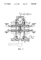
- FIG. 1 is a cross-sectional view of the substrate cooling system within the substrate processing chamber according to the invention
- FIG. 2 is a graph illustrating the thermal conductivity versus pressure for helium.
- FIGS. 3 through 8 are graphs illustrating the cool down rates of substrates under varying processing conditions according to the invention.
- a cooling chamber is provided with a pair of stationary heat sinks having substantially planar parallel facing surfaces. Once the substrate is operatively positioned between the heat sinks, with its respective outer surfaces adjacent to and substantially parallel with the facing surfaces of the heat sinks, a high thermal conductivity gas is introduced into the cooling chamber to facilitate the heat transfer from the substrate to the heat sinks.
- a highly important technical advantage of the invention is that the contiguous surfaces of the heat sinks are maintained at a predetermined close spacing with the substrate to achieve a substantial conductive/convective heat transfer and eliminating the risk of any damage to the extremely sensitive surface of the substrate or disk by heat sink contact.
- the thermal conductivity K is constant at pressures of one atmosphere and higher, with little or no dependency on the pressure. As the pressure falls below an atmosphere, the conductivity is reduced.
- the conductivity of the various gases is related to their molecular weight, with the lightest gases, such as helium and hydrogen, being the best conductors.
- FIG. 2 graphically illustrates the conductivity versus pressure for helium, as determined by recent experiments.
- the gas pressure of the processing station must be controlled to optimize conductivity at the highest practical value consistent with the vacuum system operation. This is typically done by throttling the gas flow to a high vacuum pump such that a small (total) gas flow gives a greatly elevated pressure.
- FIG. 1 is a simplified sectional view of one embodiment of the present invention.
- the substrate cooling station 1 is operatively secured to the main vacuum chamber housing 21 by conventional mounting means, such as the plurality of bolts shown in phantom, and is effectively sealed thereto by virtue of O-ring seal 22.
- the substrate cooling station 1 generally comprises two heat sink spacers 2 mounted on a pair of heat sinks 3.
- the heat sink spacers 2 are employed to conveniently set and maintain the critical spacing between the substrate 10 and the heat sinks 3.
- conduits 4 and 5 passing into and through the heat sinks 3 are provided to allow a conventional coolant to be flowed into and out of the heat sinks 3, thereby maintaining the temperature of the heat sinks 3 at the desired level.
- Temperature of the heat sinks 3 is monitored by virtue of a pair of conventional temperature sensors 6, operatively mounted on each heat sink 3, and a pair of conventional temperature sensor vacuum feedthroughs 7 operatively positioned in the processing chamber 1 housing.
- the temperature sensors 6 and feedthroughs 7 are operatively connected by leads 8, 9.
- the heat sinks 3 have a generally planar surface and are generally positioned parallel one to the other.
- the heat sink spacers 2 are tightly mounted to the heat sinks 3 to ensure that they are both at the same temperature.
- the surfaces of the heat sink spacers 2 are closely spaced to achieve a substantial convective/conductive heat transfer from the substrate 10 to the heat sinks 3, but not in contact with the substrate 10 when positioned therein, eliminating any risk of damage to the delicate substrate 10 surfaces.
- substantial convective/conductive heat transfer means a convective/conduction heat transfer in excess of 500% of the optimum heat transfer from the substrate 10 to the heat sinks 3 by radiation alone.
- An input gas conduit 21 is provided to introduce the high thermal conductivity gas, such as helium, directly into the processing chamber 20.
- the introduction of helium gas increases the rate of cooling by increasing the rate of heat transfer from the substrate 10 to the heat sinks 3.
- the heat sinks 3 comprise a high conductivity material such as copper, and are capable of cryogenic operation at approximately -130° C.
- Each of the heat sink spacers 2 are also maintained at a predetermined distance from the respective substrate 10 surface between 0.05 and 0.25 inches, preferably 0.09 inches.
- helium gas is employed as the conductive medium.
- the helium gas is introduced into the processing chamber by conduit 21 and pumped through a very small orifice or throttle plate (not shown) to a conventional high vacuum cyropump 23 mounted near the base of the processing station 1.
- the substrate 10 is moved into and out of the processing station, and loosely supported therein, on a substrate holder 11, such as that disclosed in co-pending U.S. application Ser. No. 763,183, filed Sep. 20, 1991, whereby neither of the two coated surfaces of the substrate are touched by any part of the apparatus.
- the substrate cooling station 1 may also include a pair of external handles 25 to facilitate removal and installation of the cooling station 1.
- each of the heat sinks 3 is prepositioned (i.e. spaced) between 0.05 and 0.25 inches, preferably 0.09 inches from the substrate 10.
- the heat sinks 3 are then cooled to between -50° C. and -200° C. preferably -130° C. by conventional cryogenic refrigeration.
- the substrate 10 is then positioned in the processing chamber 20 by the substrate holder 11 such that the respective outer surfaces of the substrate 10 are adjacent to and substantially parallel with the facing surfaces of the heat sink spacers 2.
- a high thermal conductivity gas such as helium or hydrogen is introduced into the processing chamber 20 while the heat sinks 3 are at their operating temperatures to increase the rate of heat transfer from the substrate 10 to the heat sinks 3.
- the gas flow is introduced and maintained at a pressure significantly above that of the processing chamber 20, yet substantially below that of the atmosphere. In the preferred embodiment the gas pressure is maintained at approximately 1 to 100 Torr, preferably 10 Torr.
- the gas flow is stopped and the throttle plate orifice (not shown) is opened.
- Another method which may be used to cool the substrate 10 is to completely close off the high vacuum pumping port (not shown) and admit enough gas for effective conduction. This involves only an initial gas flow which is then stopped when the operating pressure is reached. To stop the cooling, the high vacuum valve is then opened and the relatively small net amount of gas is pumped away, restoring high vacuum in the processing chamber 20.
- the substrate 10 After cooling the substrate 10 to a predetermined temperature, the substrate 10 is removed from the processing chamber 10 by the substrate holder 11.
- a 95 mm. dia. ⁇ 0.050" thk. un-coated (except for electroless nickel) aluminum disk was employed for the following experimental analysis.
- the disk was placed in a V-block and preheated to 300° C.
- the disk was equipped with a conventional thermocouple to closely monitor the disk temperature.
- the spacing between disk and each heat sink spacer was maintained at 0.225".
- FIG. 8 illustrates the enhanced cooling rate which was achieved using cryogenic heat sinks at -130° C.
- Table 1 The results of the above experiments are summarized in Table 1.
- the foregoing examples have set forth a substrate cooling system which effectively cools a substrate or disk during processing without any risk of damage to the delicate surfaces of the substrate or disk. This is accomplished by positioning a pair of heat sinks at a predetermined spacing such that the substrate or disk may be easily and readily positioned between the sinks, but close enough in spacing to achieve a substantial conductive/convective heat transfer from the substrate to the heat sinks with the aid of a high conductivity gas.
Landscapes
- Chemical & Material Sciences (AREA)
- Engineering & Computer Science (AREA)
- Organic Chemistry (AREA)
- Chemical Kinetics & Catalysis (AREA)
- Physics & Mathematics (AREA)
- General Physics & Mathematics (AREA)
- Automation & Control Theory (AREA)
- Materials Engineering (AREA)
- Mechanical Engineering (AREA)
- Metallurgy (AREA)
- Physical Vapour Deposition (AREA)
- Manufacturing Of Magnetic Record Carriers (AREA)
Abstract
Description
              TABLE 1
______________________________________
                        Time to Reach 150° C.
                        From 300° C. Initial
Pressure  Heat Sink Temp °C.
                        Temp.
______________________________________
High vacuum
          21° C. 625 sec.
44.4 mtorr
          21° C. 315 sec.
  84.0    21° C. 227 sec.
  125.8   21° C. 195 sec.
251       23° C. 120 sec.
242       -130° C.
                         62 sec.
______________________________________
Claims (8)
Priority Applications (5)
| Application Number | Priority Date | Filing Date | Title |
|---|---|---|---|
| US07/763,355 US5181556A (en) | 1991-09-20 | 1991-09-20 | System for substrate cooling in an evacuated environment |
| JP4262759A JP2662549B2 (en) | 1991-09-20 | 1992-09-07 | A system that cools substrates in an exhaust environment |
| DE4230807A DE4230807C2 (en) | 1991-09-20 | 1992-09-15 | Device and method for cooling substrates in an evacuated environment |
| US07/980,680 US5287914A (en) | 1991-09-20 | 1992-11-24 | System for substrate cooling in an evacuated environment |
| JP08231284A JP3083080B2 (en) | 1991-09-20 | 1996-08-14 | A system that cools substrates in an exhaust environment |
Applications Claiming Priority (1)
| Application Number | Priority Date | Filing Date | Title |
|---|---|---|---|
| US07/763,355 US5181556A (en) | 1991-09-20 | 1991-09-20 | System for substrate cooling in an evacuated environment |
Related Child Applications (1)
| Application Number | Title | Priority Date | Filing Date |
|---|---|---|---|
| US07/980,680 Continuation US5287914A (en) | 1991-09-20 | 1992-11-24 | System for substrate cooling in an evacuated environment |
Publications (1)
| Publication Number | Publication Date |
|---|---|
| US5181556A true US5181556A (en) | 1993-01-26 |
Family
ID=25067600
Family Applications (2)
| Application Number | Title | Priority Date | Filing Date |
|---|---|---|---|
| US07/763,355 Expired - Lifetime US5181556A (en) | 1991-09-20 | 1991-09-20 | System for substrate cooling in an evacuated environment |
| US07/980,680 Expired - Fee Related US5287914A (en) | 1991-09-20 | 1992-11-24 | System for substrate cooling in an evacuated environment |
Family Applications After (1)
| Application Number | Title | Priority Date | Filing Date |
|---|---|---|---|
| US07/980,680 Expired - Fee Related US5287914A (en) | 1991-09-20 | 1992-11-24 | System for substrate cooling in an evacuated environment |
Country Status (3)
| Country | Link |
|---|---|
| US (2) | US5181556A (en) |
| JP (2) | JP2662549B2 (en) |
| DE (1) | DE4230807C2 (en) |
Cited By (29)
| Publication number | Priority date | Publication date | Assignee | Title |
|---|---|---|---|---|
| US5287914A (en) * | 1991-09-20 | 1994-02-22 | Intevac, Inc. | System for substrate cooling in an evacuated environment |
| US5411076A (en) * | 1993-02-12 | 1995-05-02 | Dainippon Screen Mfg. Co., Ltd. Corp. Of Japan | Substrate cooling device and substrate heat-treating apparatus |
| US5511608A (en) * | 1995-01-04 | 1996-04-30 | Boyd; Trace L. | Clampless vacuum heat transfer station |
| US5585063A (en) * | 1994-09-12 | 1996-12-17 | Eastman Kodak Company | Apparatus and method for cooling hot disk-shaped objects |
| EP0752482A2 (en) * | 1995-07-04 | 1997-01-08 | Erich Bergmann | Method and equipment for the application of wear resistant coatings by high vacuum physical vapour deposition |
| US5883778A (en) * | 1994-02-28 | 1999-03-16 | Applied Materials, Inc. | Electrostatic chuck with fluid flow regulator |
| US6073366A (en) * | 1997-07-11 | 2000-06-13 | Asm America, Inc. | Substrate cooling system and method |
| US6083566A (en) * | 1998-05-26 | 2000-07-04 | Whitesell; Andrew B. | Substrate handling and processing system and method |
| US6108937A (en) * | 1998-09-10 | 2000-08-29 | Asm America, Inc. | Method of cooling wafers |
| US6250374B1 (en) | 1998-01-12 | 2001-06-26 | Anelva Corporation | Apparatus and method for treating substrates |
| US6259062B1 (en) | 1999-12-03 | 2001-07-10 | Asm America, Inc. | Process chamber cooling |
| WO2002005323A2 (en) * | 2000-07-06 | 2002-01-17 | Applied Materials, Inc. | Thermally processing a substrate |
| WO2002055755A1 (en) | 2001-01-11 | 2002-07-18 | D2 Systems | A method of coating insultative substrates |
| US6455101B1 (en) | 1999-07-28 | 2002-09-24 | Anelva Corporation | Method for depositing a protective carbon coating on a data recording disk |
| US6461801B1 (en) | 1999-05-27 | 2002-10-08 | Matrix Integrated Systems, Inc. | Rapid heating and cooling of workpiece chucks |
| US20030213929A1 (en) * | 2002-03-29 | 2003-11-20 | Parent Donald G. | Rotary barrel gate valve |
| US20040035847A1 (en) * | 1998-11-20 | 2004-02-26 | Arnon Gat | Fast heating and cooling apparatus for semiconductor wafers |
| US6803546B1 (en) | 1999-07-08 | 2004-10-12 | Applied Materials, Inc. | Thermally processing a substrate |
| US20040250996A1 (en) * | 2003-06-11 | 2004-12-16 | Seagate Technology Llc | Method and apparatus for cooling a planar workpiece in an evacuated environment with dynamically moveable heat sinks |
| US20040250862A1 (en) * | 2003-06-13 | 2004-12-16 | Tomonori Maruta | Ball valve |
| US6905333B2 (en) | 2002-09-10 | 2005-06-14 | Axcelis Technologies, Inc. | Method of heating a substrate in a variable temperature process using a fixed temperature chuck |
| US6957690B1 (en) | 1998-09-10 | 2005-10-25 | Asm America, Inc. | Apparatus for thermal treatment of substrates |
| US20050252227A1 (en) * | 2004-05-14 | 2005-11-17 | Intevac, Inc. | Capacitance sensing for substrate cooling |
| US20070041076A1 (en) * | 2005-08-19 | 2007-02-22 | Fan Zhong | MEMS device having support structures configured to minimize stress-related deformation and methods for fabricating same |
| US20080230721A1 (en) * | 2007-03-23 | 2008-09-25 | Asm Japan K.K. | Uv light irradiating apparatus with liquid filter |
| US20100314076A1 (en) * | 2006-09-22 | 2010-12-16 | Barth Kurt L | Apparatus and Method for Rapid Cooling of Large Area Substrates in Vacuum |
| US20110315346A1 (en) * | 2010-06-29 | 2011-12-29 | Canon Anelva Corporation | Cooling apparatus and heating apparatus |
| US8524052B1 (en) * | 2010-04-02 | 2013-09-03 | WD Media, LLC | Cooling shower plate for disk manufacture |
| US10872634B2 (en) | 2017-04-27 | 2020-12-22 | Seagate Technology Llc | Methods and devices for conditioning disks |
Families Citing this family (8)
| Publication number | Priority date | Publication date | Assignee | Title |
|---|---|---|---|---|
| US5410286A (en) * | 1994-02-25 | 1995-04-25 | General Electric Company | Quench-protected, refrigerated superconducting magnet |
| US6053982A (en) | 1995-09-01 | 2000-04-25 | Asm America, Inc. | Wafer support system |
| US6113702A (en) | 1995-09-01 | 2000-09-05 | Asm America, Inc. | Wafer support system |
| US5753092A (en) * | 1996-08-26 | 1998-05-19 | Velocidata, Inc. | Cylindrical carriage sputtering system |
| JPH11135442A (en) * | 1997-10-31 | 1999-05-21 | Canon Inc | Method and apparatus for forming deposited film |
| US20030173346A1 (en) * | 2002-03-18 | 2003-09-18 | Renken Wayne Glenn | System and method for heating and cooling wafer at accelerated rates |
| US8092606B2 (en) * | 2007-12-18 | 2012-01-10 | Asm Genitech Korea Ltd. | Deposition apparatus |
| US11397038B1 (en) * | 2017-07-18 | 2022-07-26 | Seagate Technology Llc | Coaxially pumped cooling station |
Citations (5)
| Publication number | Priority date | Publication date | Assignee | Title |
|---|---|---|---|---|
| US4457359A (en) * | 1982-05-25 | 1984-07-03 | Varian Associates, Inc. | Apparatus for gas-assisted, solid-to-solid thermal transfer with a semiconductor wafer |
| US4512391A (en) * | 1982-01-29 | 1985-04-23 | Varian Associates, Inc. | Apparatus for thermal treatment of semiconductor wafers by gas conduction incorporating peripheral gas inlet |
| US4909314A (en) * | 1979-12-21 | 1990-03-20 | Varian Associates, Inc. | Apparatus for thermal treatment of a wafer in an evacuated environment |
| US4969511A (en) * | 1989-07-03 | 1990-11-13 | Person George A | Substrate thermal interface employing helium gap |
| US5113929A (en) * | 1990-04-09 | 1992-05-19 | Anelva Corporation | Temperature control system for semiconductor wafer or substrate |
Family Cites Families (2)
| Publication number | Priority date | Publication date | Assignee | Title |
|---|---|---|---|---|
| US5198753A (en) * | 1990-06-29 | 1993-03-30 | Digital Equipment Corporation | Integrated circuit test fixture and method |
| US5181556A (en) * | 1991-09-20 | 1993-01-26 | Intevac, Inc. | System for substrate cooling in an evacuated environment |
-
1991
- 1991-09-20 US US07/763,355 patent/US5181556A/en not_active Expired - Lifetime
-
1992
- 1992-09-07 JP JP4262759A patent/JP2662549B2/en not_active Expired - Lifetime
- 1992-09-15 DE DE4230807A patent/DE4230807C2/en not_active Expired - Fee Related
- 1992-11-24 US US07/980,680 patent/US5287914A/en not_active Expired - Fee Related
-
1996
- 1996-08-14 JP JP08231284A patent/JP3083080B2/en not_active Expired - Lifetime
Patent Citations (5)
| Publication number | Priority date | Publication date | Assignee | Title |
|---|---|---|---|---|
| US4909314A (en) * | 1979-12-21 | 1990-03-20 | Varian Associates, Inc. | Apparatus for thermal treatment of a wafer in an evacuated environment |
| US4512391A (en) * | 1982-01-29 | 1985-04-23 | Varian Associates, Inc. | Apparatus for thermal treatment of semiconductor wafers by gas conduction incorporating peripheral gas inlet |
| US4457359A (en) * | 1982-05-25 | 1984-07-03 | Varian Associates, Inc. | Apparatus for gas-assisted, solid-to-solid thermal transfer with a semiconductor wafer |
| US4969511A (en) * | 1989-07-03 | 1990-11-13 | Person George A | Substrate thermal interface employing helium gap |
| US5113929A (en) * | 1990-04-09 | 1992-05-19 | Anelva Corporation | Temperature control system for semiconductor wafer or substrate |
Cited By (51)
| Publication number | Priority date | Publication date | Assignee | Title |
|---|---|---|---|---|
| US5287914A (en) * | 1991-09-20 | 1994-02-22 | Intevac, Inc. | System for substrate cooling in an evacuated environment |
| US5411076A (en) * | 1993-02-12 | 1995-05-02 | Dainippon Screen Mfg. Co., Ltd. Corp. Of Japan | Substrate cooling device and substrate heat-treating apparatus |
| US5883778A (en) * | 1994-02-28 | 1999-03-16 | Applied Materials, Inc. | Electrostatic chuck with fluid flow regulator |
| US5585063A (en) * | 1994-09-12 | 1996-12-17 | Eastman Kodak Company | Apparatus and method for cooling hot disk-shaped objects |
| US5511608A (en) * | 1995-01-04 | 1996-04-30 | Boyd; Trace L. | Clampless vacuum heat transfer station |
| EP0752482A3 (en) * | 1995-07-04 | 1998-09-09 | Erich Bergmann | Method and equipment for the application of wear resistant coatings by high vacuum physical vapour deposition |
| EP0752482A2 (en) * | 1995-07-04 | 1997-01-08 | Erich Bergmann | Method and equipment for the application of wear resistant coatings by high vacuum physical vapour deposition |
| US6578287B2 (en) | 1997-07-11 | 2003-06-17 | Asm America, Inc. | Substrate cooling system and method |
| US6073366A (en) * | 1997-07-11 | 2000-06-13 | Asm America, Inc. | Substrate cooling system and method |
| US6408537B1 (en) | 1997-07-11 | 2002-06-25 | Asm America, Inc. | Substrate cooling system |
| US6250374B1 (en) | 1998-01-12 | 2001-06-26 | Anelva Corporation | Apparatus and method for treating substrates |
| US6083566A (en) * | 1998-05-26 | 2000-07-04 | Whitesell; Andrew B. | Substrate handling and processing system and method |
| US6957690B1 (en) | 1998-09-10 | 2005-10-25 | Asm America, Inc. | Apparatus for thermal treatment of substrates |
| US6209220B1 (en) | 1998-09-10 | 2001-04-03 | Asm America, Inc. | Apparatus for cooling substrates |
| US6108937A (en) * | 1998-09-10 | 2000-08-29 | Asm America, Inc. | Method of cooling wafers |
| US20050229855A1 (en) * | 1998-09-10 | 2005-10-20 | Ivo Raaijmakers | Apparatus for thermal treatment of substrates |
| US20040035847A1 (en) * | 1998-11-20 | 2004-02-26 | Arnon Gat | Fast heating and cooling apparatus for semiconductor wafers |
| US20050183854A1 (en) * | 1998-11-20 | 2005-08-25 | Arnon Gat | Fast heating and cooling apparatus for semiconductor wafers |
| US6919271B2 (en) | 1998-11-20 | 2005-07-19 | Mattson Technology, Inc. | Method for rapidly heating and cooling semiconductor wafers |
| US7226488B2 (en) | 1998-11-20 | 2007-06-05 | Mattson Technology, Inc. | Fast heating and cooling apparatus for semiconductor wafers |
| US6461801B1 (en) | 1999-05-27 | 2002-10-08 | Matrix Integrated Systems, Inc. | Rapid heating and cooling of workpiece chucks |
| US6803546B1 (en) | 1999-07-08 | 2004-10-12 | Applied Materials, Inc. | Thermally processing a substrate |
| US6455101B1 (en) | 1999-07-28 | 2002-09-24 | Anelva Corporation | Method for depositing a protective carbon coating on a data recording disk |
| US6571729B2 (en) | 1999-07-28 | 2003-06-03 | Anelva Corporation | Apparatus for depositing a thin film on a data recording disk |
| US6259062B1 (en) | 1999-12-03 | 2001-07-10 | Asm America, Inc. | Process chamber cooling |
| US6410888B2 (en) | 1999-12-03 | 2002-06-25 | Asm America, Inc. | Process chamber cooling |
| WO2002005323A2 (en) * | 2000-07-06 | 2002-01-17 | Applied Materials, Inc. | Thermally processing a substrate |
| WO2002005323A3 (en) * | 2000-07-06 | 2002-06-20 | Applied Materials Inc | Thermally processing a substrate |
| WO2002055755A1 (en) | 2001-01-11 | 2002-07-18 | D2 Systems | A method of coating insultative substrates |
| US6983925B2 (en) | 2002-03-29 | 2006-01-10 | D2 In-Line Solutions, Llc | Rotary barrel gate valve |
| US20050058776A1 (en) * | 2002-03-29 | 2005-03-17 | Parent Donald G. | Gravity-fed in-line continuous processing system and method |
| US20060283391A1 (en) * | 2002-03-29 | 2006-12-21 | Parent Donald G | Gravity-fed in-line continuous processing system and method |
| US20030213929A1 (en) * | 2002-03-29 | 2003-11-20 | Parent Donald G. | Rotary barrel gate valve |
| US20060251814A1 (en) * | 2002-03-29 | 2006-11-09 | Parent Donald G | Gravity-fed in-line continuous processing system and method |
| US7485190B2 (en) | 2002-09-10 | 2009-02-03 | Axcelis Technologies, Inc. | Apparatus for heating a substrate in a variable temperature process using a fixed temperature chuck |
| US20050166845A1 (en) * | 2002-09-10 | 2005-08-04 | Gerald Cox | Method of heating a substrate in a variable temperature process using a fixed temperature chuck |
| US6905333B2 (en) | 2002-09-10 | 2005-06-14 | Axcelis Technologies, Inc. | Method of heating a substrate in a variable temperature process using a fixed temperature chuck |
| US20040250996A1 (en) * | 2003-06-11 | 2004-12-16 | Seagate Technology Llc | Method and apparatus for cooling a planar workpiece in an evacuated environment with dynamically moveable heat sinks |
| US8701753B2 (en) | 2003-06-11 | 2014-04-22 | Seagate Technology Llc | Method and apparatus for cooling a planar workpiece in an evacuated environment with dynamically moveable heat sinks |
| US20040250862A1 (en) * | 2003-06-13 | 2004-12-16 | Tomonori Maruta | Ball valve |
| WO2005114074A1 (en) | 2004-05-14 | 2005-12-01 | Intevac, Inc. | Capacitance sensing for substrate cooling |
| US20050252227A1 (en) * | 2004-05-14 | 2005-11-17 | Intevac, Inc. | Capacitance sensing for substrate cooling |
| US7000418B2 (en) | 2004-05-14 | 2006-02-21 | Intevac, Inc. | Capacitance sensing for substrate cooling |
| US7747109B2 (en) | 2005-08-19 | 2010-06-29 | Qualcomm Mems Technologies, Inc. | MEMS device having support structures configured to minimize stress-related deformation and methods for fabricating same |
| US20070041076A1 (en) * | 2005-08-19 | 2007-02-22 | Fan Zhong | MEMS device having support structures configured to minimize stress-related deformation and methods for fabricating same |
| US20100314076A1 (en) * | 2006-09-22 | 2010-12-16 | Barth Kurt L | Apparatus and Method for Rapid Cooling of Large Area Substrates in Vacuum |
| US8302554B2 (en) * | 2006-09-22 | 2012-11-06 | Colorada State University Research Foundation. | Apparatus and method for rapid cooling of large area substrates in vacuum |
| US20080230721A1 (en) * | 2007-03-23 | 2008-09-25 | Asm Japan K.K. | Uv light irradiating apparatus with liquid filter |
| US8524052B1 (en) * | 2010-04-02 | 2013-09-03 | WD Media, LLC | Cooling shower plate for disk manufacture |
| US20110315346A1 (en) * | 2010-06-29 | 2011-12-29 | Canon Anelva Corporation | Cooling apparatus and heating apparatus |
| US10872634B2 (en) | 2017-04-27 | 2020-12-22 | Seagate Technology Llc | Methods and devices for conditioning disks |
Also Published As
| Publication number | Publication date |
|---|---|
| JPH09118982A (en) | 1997-05-06 |
| DE4230807A1 (en) | 1993-03-25 |
| JP2662549B2 (en) | 1997-10-15 |
| DE4230807C2 (en) | 1999-02-25 |
| JP3083080B2 (en) | 2000-09-04 |
| US5287914A (en) | 1994-02-22 |
| JPH05197953A (en) | 1993-08-06 |
Similar Documents
| Publication | Publication Date | Title |
|---|---|---|
| US5181556A (en) | System for substrate cooling in an evacuated environment | |
| US5775416A (en) | Temperature controlled chuck for vacuum processing | |
| JP2766774B2 (en) | Method for cooling and heating large area glass substrate and apparatus therefor | |
| US6193811B1 (en) | Method for improved chamber bake-out and cool-down | |
| EP0480735B1 (en) | Differential pressure CVD chuck | |
| EP0465185B1 (en) | Vacuum processing method and apparatus | |
| US6133550A (en) | Method and apparatus for thermal processing of semiconductor substrates | |
| US6765178B2 (en) | Chamber for uniform substrate heating | |
| JP3164248B2 (en) | Heat treatment equipment | |
| GB2114813A (en) | Apparatus for thermal treatment of semiconductor wafers by gas conduction incorporating peripheral gas inlet | |
| US20020047004A1 (en) | System and method for thermal processing of a semiconductor substrate | |
| JP5034138B2 (en) | Heat treatment method and heat treatment apparatus | |
| US5183402A (en) | Workpiece support | |
| US11015262B2 (en) | Apparatus and method for molecular beam epitaxy | |
| US20040250996A1 (en) | Method and apparatus for cooling a planar workpiece in an evacuated environment with dynamically moveable heat sinks | |
| TWI795492B (en) | Deposition processing systems having active temperature control and associated methods | |
| WO1999055931A1 (en) | Low pressure purging method | |
| JP2005281784A (en) | Cooling structure for substrate | |
| JPH07302785A (en) | Apparatus for treatment of substrate and control of substrate temperature | |
| JPS5922932A (en) | Preparation of thin film | |
| GB2338288A (en) | Temperature controlled chuck for vacuum processing | |
| JPH04173977A (en) | Susceptor for vapor growth device | |
| JPH0440227A (en) | Ultrahigh vacuum apparatus | |
| JPS62134924A (en) | Holder for substrate heating | |
| JPH06290864A (en) | Vacuum heating processing device |
Legal Events
| Date | Code | Title | Description |
|---|---|---|---|
| AS | Assignment |
Owner name: INTEVAC, INC., A CA CORP., CALIFORNIA Free format text: ASSIGNMENT OF ASSIGNORS INTEREST.;ASSIGNOR:HUGHES, JOHN L.;REEL/FRAME:006190/0408 Effective date: 19910930 |
|
| STCF | Information on status: patent grant |
Free format text: PATENTED CASE |
|
| AS | Assignment |
Owner name: SILICON VALLEY BANK, CALIFORNIA Free format text: SECURITY INTEREST;ASSIGNOR:INTEVAC, INC.;REEL/FRAME:006747/0087 Effective date: 19930708 |
|
| FPAY | Fee payment |
Year of fee payment: 4 |
|
| RR | Request for reexamination filed |
Effective date: 19960930 |
|
| FEPP | Fee payment procedure |
Free format text: PAYOR NUMBER ASSIGNED (ORIGINAL EVENT CODE: ASPN); ENTITY STATUS OF PATENT OWNER: SMALL ENTITY |
|
| FEPP | Fee payment procedure |
Free format text: PAT HOLDER CLAIMS SMALL ENTITY STATUS - SMALL BUSINESS (ORIGINAL EVENT CODE: SM02); ENTITY STATUS OF PATENT OWNER: SMALL ENTITY |
|
| FPAY | Fee payment |
Year of fee payment: 8 |
|
| FEPP | Fee payment procedure |
Free format text: PAYER NUMBER DE-ASSIGNED (ORIGINAL EVENT CODE: RMPN); ENTITY STATUS OF PATENT OWNER: SMALL ENTITY |
|
| FPAY | Fee payment |
Year of fee payment: 12 |