US5185735A - Lan noise monitor - Google Patents
Lan noise monitor Download PDFInfo
- Publication number
- US5185735A US5185735A US07/727,693 US72769391A US5185735A US 5185735 A US5185735 A US 5185735A US 72769391 A US72769391 A US 72769391A US 5185735 A US5185735 A US 5185735A
- Authority
- US
- United States
- Prior art keywords
- voltage
- lan
- lan cable
- positive voltage
- electrically connected
- Prior art date
- Legal status (The legal status is an assumption and is not a legal conclusion. Google has not performed a legal analysis and makes no representation as to the accuracy of the status listed.)
- Expired - Lifetime
Links
Images


Classifications
-
- H—ELECTRICITY
- H04—ELECTRIC COMMUNICATION TECHNIQUE
- H04L—TRANSMISSION OF DIGITAL INFORMATION, e.g. TELEGRAPHIC COMMUNICATION
- H04L43/00—Arrangements for monitoring or testing data switching networks
-
- H—ELECTRICITY
- H04—ELECTRIC COMMUNICATION TECHNIQUE
- H04L—TRANSMISSION OF DIGITAL INFORMATION, e.g. TELEGRAPHIC COMMUNICATION
- H04L43/00—Arrangements for monitoring or testing data switching networks
- H04L43/08—Monitoring or testing based on specific metrics, e.g. QoS, energy consumption or environmental parameters
- H04L43/0805—Monitoring or testing based on specific metrics, e.g. QoS, energy consumption or environmental parameters by checking availability
- H04L43/0811—Monitoring or testing based on specific metrics, e.g. QoS, energy consumption or environmental parameters by checking availability by checking connectivity
Definitions
- the present invention relates generally to an apparatus and method for detecting problems with local area network (LAN) hardware. More particularly, the present invention relates to an apparatus and method for detecting noise on a LAN cable.
- LAN local area network
- a standard local area network comprises a plurality of nodes connected to one another through a coaxial cable (called a LAN cable).
- the nodes communicate by sending packets of binary signals to one another.
- the binary signals comprise transitions between 0 and -2 volts.
- a packet comprises a preamble, an address and the data to be communicated.
- the preamble is a sequence of -2 volt pulses to identify the beginning of the packet.
- the address is a number identifying the node to which the packet is being sent.
- the data is all or a portion of a information to be communicated between two nodes, for example.
- the LAN cable can only convey one packet at a time. Therefore, before sending a packet, a node must determine that there are no packets currently being transmitted over the LAN cable. A node will make such a determination if the average voltage level on the LAN cable (called the DC bias) is lower than a particular voltage level (called the signal detect level).
- the signal detect level could be, for example, -0.3 volts.
- the determination is based on the following. During transmission of the preamble, the sequence of -2 volt pulses brings the DC bias down to approximately one-half the peak voltage (-1 volt). Because this voltage is below the signal detect level, a node would detect a packet on the LAN cable.
- the voltage on the LAN cable is likewise below the signal detect level.
- the binary representation of addresses and data is encoded so that there is a limited amount of time between transitions of 0 and -2 volts. The limited amount of time is too short for the DC bias to rise much above -1 volt.
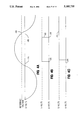
- FIG. 1A shows the level of a DC bias 102 during the first several pulses of a first preamble 104.
- the sequence of -2 volt pulses brings the DC bias 102 down to -1 volt. Because this is below the signal detect level, other nodes on the LAN are capable of determining that there is a packet being transmitted over the LAN cable. Therefore, generally, no other node will send a packet.
- a collision occurs when two nodes send packets approximately simultaneously.
- a node must continue to monitor the DC bias while it is transmitting.
- a node determines that a collision has occurred if the DC bias drops below a particular voltage level called the collision detect level. The latter is approximately -1.3 volts.
- the determination is based on the following. If two nodes are simultaneously transmitting, they will bring the DC bias 102 to approximately twice what it would be if only one node were transmitting. Therefore, during a collision, the DC bias 102 is approximately -2 volts, which is below the collision detect level.
- transmitting nodes Upon detecting a collision, transmitting nodes continue to transmit for a short period of time to enable other nodes to detect the collision. Subsequently, all nodes temporarily cease transmitting.
- FIG. 1A shows the level of the DC bias 102 during the first several pulses of second and third preambles 108 and 109 which collide.
- the second preamble 108 initially brings the DC bias 102 below the signal detect level.
- the third preamble 109 begins.
- the -2 volt pulses of the second preamble 108 overlap the -2 volt pulses of the third preamble 109 (as shown at 110), pulling the peak voltage to -4 volts.
- the overlapping preambles 110 bring the DC bias 102 down to one-half the peak voltage (-2 volts). This level is below the collision detect level, and a collision is therefore detected.
- the pulses of the second and third preambles 108 and 109 are approximately 90 degrees out of phase. Note that overlapping preambles would bring the DC bias 102 below the collision detect level regardless of how they overlapped. For example, if the pulses were 180 degrees out of phase, they would combine to place a steady -2 volt signal on the LAN cable and thereby bring the DC bias 102 to -2 volts. Alternatively, if the pulses were in phase with one another, they would combine to produce a square wave with a -4 volt peak. Again, the DC bias 102 would be -2 volts.
- Noise on a LAN cable can substantially interfere with the transmission of packets.
- the most common source of noise on a LAN cable is commercial power resulting from two or more grounds on the LAN cable.
- a ground can be caused by, for example, an improperly insulated LAN cable or a faulty media attachment unit (MAU).
- MAU media attachment unit
- FIG. 1B shows a LAN 100 having a LAN cable 120 which is grounded in two places to thereby transmit commercial power.
- the LAN cable 120 comprises an center conductor 122 and an outer conductor 124.
- the center conductor 122 is electrically connected to the outer conductor 124 through a 25 ohm resistor 128.
- Each of two nodes 134 is attached to the LAN cable 120 through a faulty MAU 136. (The faults of the MAUs are depicted as ground connections off the MAUs.) Each MAU 136 is electrically connected to the LAN cable 120 through a "T" connection 138. Each MAU 136 is electrically connected to one of the nodes 134 through an Attachment Unit Interface (AUI) cable 140.
- AUI Attachment Unit Interface
- FIG. 2 shows how noise from a commercial power source can interfere with data transmissions on the LAN 100 of FIG. 1B.
- a noise curve 202 represents noise from a commercial power source. The noise interferes with packet transmission because the DC bias is relative to the noise level.
- the noise curve 202 is at a noise positive peak.
- the DC bias 206 during transmission of the first packet 204 is above the signal detect level. As a result, the first packet 204 is not detected.
- the noise curve 202 is at approximately 0 volts.
- the DC bias 208 during the second packet 206 is approximately -1 volt, which is between the signal detect level and the collision detect level. The second packet 206 therefore transmits normally.
- the noise curve 202 During the time when the noise curve 202 is close to a noise negative peak, the noise curve 202, and thus the DC bias 210, are below the signal detect level.
- the nodes 134 interpret the noise as a packet and cease transmitting until the noise curve rises above the signal detect level.
- the noise curve 202 is slightly above the signal detect level.
- the DC bias 214 during transmission of the third packet 212 falls below the collision detect level.
- the third packet 212 is therefore interpreted as a collision.
- LAN noise from a source of commercial power is generally addressed by detecting its presence, locating its origin and eliminating it.
- Several well-known approaches are used to detect LAN noise.
- One such approach is by measuring the total power on the LAN cable 120. Because signals as well as noise generate power, this approach can only be used when no nodes 134 are transmitting. Accordingly, all nodes 134 must be turned off before the measurement is taken. Doing so would be undesirable on a busy network.
- a second approach for detecting LAN noise would be to check for shorts to ground using an ohmmeter. But detection of a ground does not necessarily indicate the presence of LAN noise because LAN noise only occurs when the LAN cable 120 is grounded in more than one place.
- a third approach is to search for certain collision patterns indicative of LAN noise. This is often impractical because such patterns are topologically dependent. Much domain-specific information is therefore required to detect them.
- a fourth approach is to examine a LAN cable 120 with an oscilloscope. This approach is often impractical because of the high level of expertise required by the oscilloscope operator in order to distinguish noise from data. Also, oscilloscopes generally ground the LAN cable 120 during measurement. Thus, an oscilloscope would not be effective on a LAN cable 120 which was grounded exactly once. Furthermore, the limited portability of oscilloscopes makes the fourth approach difficult to physically carry out.
- the present invention is directed towards an apparatus and method for monitoring voltage on a LAN cable on which data is conveyed by negative-going pulses.
- the apparatus and method of the present invention called a LAN noise monitor, interprets any positive voltage on the LAN cable as noise.
- the LAN noise monitor of the present invention detects positive voltage on the LAN cable by, for example, comparing the voltage on the LAN cable to a positive referential voltage, determining the peak positive voltage on the LAN cable, or determining the average positive voltage on the LAN cable.
- the LAN noise monitor indicates the presence (and possibly the amount) of noise to a LAN sentinel.
- the LAN sentinel could be, for example, a person or data processing system which supervises the LAN.
- the LAN noise monitor interprets positive voltage as noise and because data is conveyed on the LAN cable by negative-going pulses, it operates without disrupting the LAN.
- the LAN noise monitor could be implemented in a Media Attachment Unit (MAU) with means to audibly visually or electronically indicate the presence or amount of noise.
- MAU Media Attachment Unit
- FIG. 1A shows a timing diagram of the DC bias of a LAN cable during the first few pulses of a preamble and during the first few pulses of two overlapping preambles;
- FIG. 1B shows a LAN cable which is grounded in two places by faulty MAUs and thereby transmits commercial power
- FIG. 2 shows a timing diagram of packets being transmitted on a LAN cable with noise from a source of commercial power
- FIG. 3 shows a block diagram of a comparator LAN noise monitor
- FIG. 4A shows a timing diagram of the DC bias on a LAN cable with noise from a source of commercial power
- FIG. 4B shows a timing diagram of the output voltage of a comparator of the comparator LAN noise monitor of FIG. 3 when monitoring the voltage on the LAN cable of FIG. 4A;
- FIG. 4C shows a timing diagram of the output voltage of a pulse stretcher of the comparator LAN noise monitor of FIG. 3 when monitoring the voltage on the LAN cable of FIG. 4A;
- FIG. 5 shows a block diagram of a peak detecting lan noise monitor
- FIG. 6A shows a timing diagram of the DC bias on a LAN cable with noise from a source of commercial power
- FIG. 6B shows a timing diagram of the output voltage of a comparator of the peak detecting LAN noise monitor of FIG. 5 when monitoring the voltage on the LAN cable of FIG. 6A;
- FIG. 6C shows a timing diagram of the output voltage of a node A of the peak detecting LAN noise monitor of FIG. 5 when monitoring the voltage on the LAN cable of FIG. 6A;
- FIG. 7 shows a block diagram of an average detecting LAN noise monitor
- FIG. 8A shows a timing diagram of the DC bias on a LAN cable with noise from a source of commercial power
- FIG. 8B shows a timing diagram of the output voltage of a half-wave rectifier of the peak detecting LAN noise monitor of FIG. 7 when monitoring the voltage on the LAN cable of FIG. 8A;
- FIG. 8C shows a timing diagram of the output voltage of a node B of the peak detecting LAN noise monitor of FIG. 7 when monitoring the voltage on the LAN cable of FIG. 8A;
- FIG. 9 shows a block diagram of a LAN noise monitor as implemented in a MAU.
- FIG. 10 shows a block diagram of a LAN having a plurality of the LAN noise monitors of FIG. 9 providing input to a sentinel node.
- the present invention is based on the principle that positive voltage on the LAN cable 120 is generally noise, and that commercial power, the predominant source of noise, has a positive voltage component. Accordingly, the LAN noise monitor of the present invention is directed towards an apparatus and method for monitoring the voltage level on the LAN cable 120, and indicating its presence to a LAN sentinel.
- the LAN sentinel could be, for example, a person or data processing system which supervises the LAN.
- a first embodiment of the present invention is a comparator LAN noise monitor 300.
- FIG. 3 shows a block diagram of an implementation of the comparator LAN noise monitor 300.
- Other ways to implement the comparator LAN noise monitor 300 would be obvious to one of ordinary skill in the art.
- the comparator LAN noise monitor 300 generates an indication to the LAN sentinel when the voltage level on the LAN cable 120 has exceeded a specified reference voltage.
- the comparator LAN noise monitor 300 comprises a reference voltage generator 310, a sensitivity adjuster 312, a comparator 314, a pulse stretcher 316 and a positive voltage indicator 318.
- the reference voltage generator 310 generates a signal having a specified voltage level.
- the generator 310 could comprise, for example, a voltage source such as a battery and a simple voltage divider.
- the sensitivity adjustor 312 is incorporated in the reference voltage generator 310 to permit the LAN sentinel to vary the reference voltage.
- the sensitivity adjuster 312 could comprise, for example, a potentiometer.
- the comparator 314 receives as input the signal from the reference voltage generator 310 and a signal from the LAN cable 120.
- the comparator generates a first digital signal (for example, 0 volts) when the voltage level of the signal from the reference voltage generator 310 exceeds that of the signal from the LAN cable 120, and a second digital signal (for example, 5 volts) otherwise.
- the pulse stretcher 316 receives as input the signal generated by the comparator 314.
- the pulse stretcher 316 generates a low voltage signal until the output of the comparator 314 goes high.
- the pulse stretcher 316 generates a high voltage signal for at least the duration of a cycle of commercial power after detecting the second digital signal from the comparator 314.
- the comparator 314 could be an LM3111 comparator.
- the pulse stretcher 316 could comprise off-the-shelf components which are well known to those of ordinary skill in the art.
- the positive voltage indicator 318 receives input from the pulse stretcher 316. It could comprise an operational amplifier (op amp) such as an LM358. It provides an audible, visual or electrical indication to the LAN sentinel when it receives a high voltage signal from the pulse stretcher 316. For example, as shown in FIG. 9, the positive voltage indicator 318 could indicate by lighting a LED 914 or generating a tone which is audible via a speaker 916.
- op amp operational amplifier
- FIGS. 4A, 4B and 4C show timing diagrams which illustrate the operation of the comparator LAN noise monitor 300 when there is noise from a commercial power source on the LAN cable 120.
- FIG. 4A shows a LAN cable voltage 410;
- FIG. 4B shows a comparator output voltage 412 (the output of the comparator 314); and
- FIG. 4C shows a pulse stretcher output voltage 414 (the output of the pulse stretcher 316).
- the cable voltage 410 rises above the reference voltage at a time 416.
- the comparator 314 switches from generating the first digital signal to the second digital signal.
- the comparator output voltage 412 switches from a low voltage such as 0 volts to a high voltage such as 5 volts.
- the output of the pulse stretcher 316 switches from the low voltage volts to the high voltage.
- the cable voltage 410 falls below the reference voltage.
- the comparator 314 and, correspondingly, the comparator output voltage 412, switches from the high voltage to the low voltage.
- the level of the pulse stretcher output voltage 414 remains at 5 volts.
- a second embodiment of the present invention is a peak detecting LAN noise monitor 500.
- FIG. 5 shows a circuit diagram of an implementation of the peak detecting LAN noise monitor 500.
- Other ways to implement the peak detecting LAN noise monitor 500 would be obvious to one of ordinary skill in the art.
- the peak detecting LAN noise monitor 500 generates an output signal which indicates the positive peak level detected on an input signal from the LAN cable 120.
- the peak detecting LAN noise monitor 500 comprises a comparator 510; a NPN transistor 512; a capacitor 516; first, second and third resistors 518, 520, 522, respectively; and the positive voltage indicator 318 of FIG. 3.
- the peak detecting LAN noise monitor 500 could comprise off-the-shelf components such as an LM3111 comparator, a 2N3904 NPN transistor and a LM358 op amp.
- a non-inverting input 524 of the comparator 510 is electrically connected to the LAN cable 120 through the first resistor 518.
- a first end of the capacitor 516 is electrically connected to an inverting input 526 of the comparator 510.
- the first end of the capacitor 516 is also connected to ground through the second resistor 520; to an emitter 536 of the NPN transistor 512 through the third resistor 522; and to the input of the positive voltage indicator 318.
- the second end of the capacitor 516 is electrically connected to ground.
- a base 532 of the NPN transistor 512 is electrically connected to the output of the comparator 510.
- a collector 538 of the NPN transistor 512 is electrically connected to a voltage source V DD of, for example, approximately 5 volts.
- the peak detector LAN noise monitor 500 operates as follows. When the voltage level on the LAN cable 120 exceeds the voltage level at a node A (located at the first end of the capacitor 516), the comparator 510 generates a high voltage signal. The high voltage signal at the base 532 of the NPN transistor 512 causes the voltage source to charge the capacitor 516.
- the output of the comparator 510 switches to a low voltage signal, thereby tuning off the NPN transistor 512.
- the capacitor 516 then discharges through the second resistor 520.
- the size of the capacitor 516 and the resistor 520 are selected so that the capacitor discharges slowly enough to clearly indicate the peak voltage on the LAN cable 120 to the LAN sentinel, but charges fast enough to catch peaks of relatively short duration.
- the capacitor 516 might have a capacitance of 10 microfarads
- the second resistor 520 might have a resistance of 100 k ohms.
- FIGS. 6A, 6B and 6C show timing diagrams which illustrate the operation of the peak detector LAN noise monitor 500 when there is noise from a commercial power source on the LAN cable 120.
- FIG. 6A shows a LAN cable voltage 610.
- FIG. 6B shows a comparator output voltage 612 (the output of the comparator 510).
- FIG. 6C shows a voltage at a node A (the voltage across the capacitor 516).
- the LAN cable voltage 610 rises above 0 volts at 616 and continues to rise until 618, when it reaches a peak positive voltage.
- the comparator output voltage 612 then pulses high for the short period of time it takes for the voltage source to charge the capacitor 516 to the voltage level on the LAN cable 120.
- the comparator output voltage 612 continues to pulse high for short periods of time until the level of the LAN cable voltage 610 stops increasing at 618.
- Each time the comparator output voltage 612 pulse high current flows through the NPN transistor 512, permitting the voltage source V DD to charge the capacitor 516. As a result, the voltage at node A increases a small amount every time the comparator output voltage 612 pulses high.
- the capacitor voltage 614 When the LAN cable voltage 610 stops increasing at 618, the capacitor voltage 614 will be at the peak positive voltage. Because the capacitor 516 discharges slowly, the voltage at node A remains at approximately the peak positive voltage for at least the duration of a cycle of the LAN cable voltage 610.
- a third embodiment of the present invention is an average detecting LAN noise monitor 700 which generates an output signal at a level of the average positive level detected on an input signal.
- FIG. 7 shows a block diagram of an implementation of the average detecting LAN noise monitor 700.
- Other ways to implement the average detecting LAN noise monitor 500 would be obvious to one of ordinary skill in the art.
- the average detecting LAN noise monitor 700 of FIG. 7 comprises a half-wave rectifier 710, a resistor 712, a capacitor 714 and the positive voltage indicator 318 of FIG. 3.
- the half-wave rectifier 710 could comprise off-the-shelf components, such as a LM358 op amp, which are well known to those of ordinary skill in the art.
- the half-wave rectifier 710 receives input from the LAN cable 120 and provides output to a node B (located at the first end of the capacitor 714).
- the first end of the capacitor 714 is also electrically connected to the input of the positive voltage indicator 318.
- the second end of the capacitor 714 is connected to ground.
- FIGS. 8A, 8B and 8C show timing diagrams which illustrate the operation of the average detector LAN noise monitor 700 when there is noise from a commercial power source on the LAN cable 120.
- FIG. 8A shows a LAN cable voltage 810;
- FIG. 8B shows a half-wave rectifier output voltage 812 (the output of the half-wave rectifier 710); and
- FIG. 8C shows a node B voltage 814 (the voltage at the node B).
- the LAN cable voltage 810 is a 60 Hz sinusoidal wave (representing commercial power) which rises above 0 volts at 816, peaks at a peak positive voltage, falls below 0 volts at 818, and again rises above 0 volts at 820, peaks at the peak positive voltage, and falls below 0 volts at 822.
- the half-wave rectifier output 812 follows positive voltage signals of the LAN cable output 810. Accordingly, the half-wave rectifier output 812 follows the LAN cable output from 0 volts to the peak positive voltage to 0 volts between 816 and 818, and again between 820 and 822.
- the half-wave rectifier output 812 charges the capacitor 714 between 816 and 818, and again between 820 and 822 with an average voltage of half the peak positive voltage.
- the size of the capacitor 714 and the resistor 712 are chosen so that there is minimal discharge during the negative portion of the LAN cable voltage 810.
- the capacitor 714 might have a capacitance of 10 microfarads
- the resistor 712 might have a resistance of 100 k ohms.
- the node B voltage 814 rises to (peak positive output)/2.
- the node B voltage 814 remains at (peak positive output)/2 for at least the duration of a cycle of the LAN cable voltage 810.
- FIG. 9 shows a MAU LAN noise monitor 900.
- the MAU LAN noise monitor 900 is electrically connected to the LAN cable 120 through the "T" connection 138, and to the node 134 through the AUI cable 140.
- the MAU LAN noise monitor 900 could have a sensitivity adjustment 912 and noise indication means such as a LED 914, a speaker 916, an electrical signal (not shown), or some combination thereof.
- the sensitivity adjustment 912 is a means for manipulating the sensitivity adjuster 312 of FIG. 3. It could be, for example, a knob connected to a potentiometer operating a voltage or current divider. The alarm 318 would light the LED 914, activate the speaker 916 or initiate the electrical signal when the comparator LAN noise monitor 300 detected voltage on the LAN cable 120 in excess of the reference voltage.
- the MAU LAN noise monitor 900 could have a more precise indicator of the voltage on the LAN cable 120 such as a bar graph of LEDs or an analog meter (not shown). Also, in such an implementation the MAU LAN noise monitor 900 would not have a sensitivity adjustment 912.
- FIG. 10 shows a block diagram of a LAN which enables the LAN sentinel to do so.
- a number of nodes 134 are electrically connected to the LAN cable 120 through MAU LAN noise monitors 900.
- the MAU LAN noise monitors 900 could indicate any noise they detected by sending electrical signals over the LAN cable 120.
- a sentinel node 1010 which is also electrically connected to the LAN cable 120 through a MAU LAN noise monitor 900, could monitor such signals.
- a LAN sentinel 1012 communicates the sentinel node 1010 through a path 1014.
- a hand-held LAN noise monitor (not shown) would be most useful as a peak detector LAN noise monitor 500 or an average detector LAN noise monitor 700.
- the hand-held LAN noise monitor would have a visual indicator of voltage such as a bar graph of LEDs or an analog meter. To increase portability, it would likely be powered by batteries.
- a human LAN sentinel 1012 could use the hand-held LAN noise monitor to detect the level of noise at various points on the LAN cable 120. He or she would do so by electrically connecting the apparatus to the LAN cable 120 and reading the visual indicator.
Abstract
Description
Claims (20)
Priority Applications (4)
| Application Number | Priority Date | Filing Date | Title |
|---|---|---|---|
| US07/727,693 US5185735A (en) | 1991-07-10 | 1991-07-10 | Lan noise monitor |
| DE69228900T DE69228900T2 (en) | 1991-07-10 | 1992-06-18 | LAN interference voltage monitor |
| EP92305599A EP0524726B1 (en) | 1991-07-10 | 1992-06-18 | LAN noise monitor |
| JP18255692A JP3283294B2 (en) | 1991-07-10 | 1992-07-09 | LAN noise monitor |
Applications Claiming Priority (1)
| Application Number | Priority Date | Filing Date | Title |
|---|---|---|---|
| US07/727,693 US5185735A (en) | 1991-07-10 | 1991-07-10 | Lan noise monitor |
Publications (1)
| Publication Number | Publication Date |
|---|---|
| US5185735A true US5185735A (en) | 1993-02-09 |
Family
ID=24923632
Family Applications (1)
| Application Number | Title | Priority Date | Filing Date |
|---|---|---|---|
| US07/727,693 Expired - Lifetime US5185735A (en) | 1991-07-10 | 1991-07-10 | Lan noise monitor |
Country Status (4)
| Country | Link |
|---|---|
| US (1) | US5185735A (en) |
| EP (1) | EP0524726B1 (en) |
| JP (1) | JP3283294B2 (en) |
| DE (1) | DE69228900T2 (en) |
Cited By (27)
| Publication number | Priority date | Publication date | Assignee | Title |
|---|---|---|---|---|
| US5295132A (en) * | 1991-08-27 | 1994-03-15 | The Furukawa Electric Co., Ltd. | Multiplex transmission apparatus with transmission line fault detection |
| US5329519A (en) * | 1990-12-07 | 1994-07-12 | Hewlett Packard Company | Lan monitoring method and apparatus |
| US5389882A (en) * | 1990-12-07 | 1995-02-14 | Hewlett-Packard Company | LAN measurement apparatus for determining voltage between packets |
| US5504736A (en) * | 1992-05-11 | 1996-04-02 | At&T Corp. | Non-invasive link monitor |
| US5532603A (en) * | 1995-01-27 | 1996-07-02 | Fluke Corporation | Cross-talk measurement apparatus with near-end compensation |
| US5559427A (en) * | 1994-04-04 | 1996-09-24 | Fluke Corporation | Instrument and method for testing local area network cables |
| US5561383A (en) * | 1994-11-04 | 1996-10-01 | International Business Machines Corporation | Switchable peak/average detect circuit |
| US5570029A (en) * | 1994-03-30 | 1996-10-29 | Fluke Corporation | Cable crosstalk measurement system |
| US5633801A (en) * | 1995-10-11 | 1997-05-27 | Fluke Corporation | Pulse-based impedance measurement instrument |
| US5698985A (en) * | 1996-02-12 | 1997-12-16 | Fluke Corporation | Cross-talk measurement instrument with source indication as a function of distance |
| US5821760A (en) * | 1996-07-31 | 1998-10-13 | Fluke Corporation | Method and apparatus for measuring near-end cross-talk in patch cords |
| US6169475B1 (en) * | 1998-03-30 | 2001-01-02 | Xircom, Inc. | System and method for active detection of connection to a network |
| US6341358B1 (en) * | 1998-09-14 | 2002-01-22 | Compaq Computer Corporation | Integrity tester for parallel signal bus |
| US20020101874A1 (en) * | 2000-11-21 | 2002-08-01 | Whittaker G. Allan | Physical layer transparent transport information encapsulation methods and systems |
| US20030174680A1 (en) * | 2002-03-14 | 2003-09-18 | Chia-Chee Kuan | Detecting a hidden node in a wireless local area network |
| US20040062474A1 (en) * | 2002-09-27 | 2004-04-01 | Whittaker G. Allan | Optical interface devices having balanced amplification |
| US20040076434A1 (en) * | 2002-09-27 | 2004-04-22 | Whittaker G. Allan | Optical distribution network for RF and other analog signals |
| US6795402B1 (en) | 1996-01-29 | 2004-09-21 | Vigilant Networks Llc | Packet network monitoring device |
| US6829223B1 (en) | 1998-12-31 | 2004-12-07 | Vigilant Networks Llc | Computer network physical-layer analysis method and system |
| US20050213973A1 (en) * | 2003-03-31 | 2005-09-29 | Rohrer Thomas J | Optical network interface systems and devices |
| US7085497B2 (en) | 2002-04-03 | 2006-08-01 | Lockheed Martin Corporation | Vehicular communication system |
| US7283480B1 (en) | 2002-11-12 | 2007-10-16 | Lockheed Martin Corporation | Network system health monitoring using cantor set signals |
| US7349629B1 (en) | 2002-11-26 | 2008-03-25 | Lockheed Martin Corporation | Methods and systems for creating a digital interconnect fabric |
| US7424228B1 (en) | 2003-03-31 | 2008-09-09 | Lockheed Martin Corporation | High dynamic range radio frequency to optical link |
| US7440699B1 (en) | 2004-06-28 | 2008-10-21 | Lockheed Martin Corporation | Systems, devices and methods for transmitting and receiving signals on an optical network |
| USRE41247E1 (en) | 1997-04-01 | 2010-04-20 | Lockheed Martin Corporation | Optical transport system |
| US10281495B2 (en) | 2012-06-14 | 2019-05-07 | Mitsubishi Electric Corporation | Analysis device, analysis method, and program |
Families Citing this family (1)
| Publication number | Priority date | Publication date | Assignee | Title |
|---|---|---|---|---|
| AU2002222540A1 (en) * | 2001-11-26 | 2003-06-10 | Sielte S.P.A. | System and method for monitoring optical fiber cables |
Citations (3)
| Publication number | Priority date | Publication date | Assignee | Title |
|---|---|---|---|---|
| US3341816A (en) * | 1964-03-20 | 1967-09-12 | Hughes Aircraft Co | Amplitude range signal monitoring device |
| JPS564957A (en) * | 1979-06-26 | 1981-01-19 | Fujitsu Ltd | Bus circuit |
| US4916570A (en) * | 1989-05-11 | 1990-04-10 | Micron Technology, Inc. | Voltage comparator circuit for monitoring a process output voltage within a preset range |
Family Cites Families (3)
| Publication number | Priority date | Publication date | Assignee | Title |
|---|---|---|---|---|
| US4931791A (en) * | 1987-06-25 | 1990-06-05 | Digital Equipment Corporation | Shorted-coaxial-cable detector for local-area networks |
| US4799211A (en) * | 1987-07-23 | 1989-01-17 | Digital Equipment Corporation | Apparatus and method for storing performance parameters of local area network system members |
| JP2805151B2 (en) * | 1989-02-15 | 1998-09-30 | 古河電気工業株式会社 | Fault diagnosis device |
-
1991
- 1991-07-10 US US07/727,693 patent/US5185735A/en not_active Expired - Lifetime
-
1992
- 1992-06-18 EP EP92305599A patent/EP0524726B1/en not_active Expired - Lifetime
- 1992-06-18 DE DE69228900T patent/DE69228900T2/en not_active Expired - Fee Related
- 1992-07-09 JP JP18255692A patent/JP3283294B2/en not_active Expired - Fee Related
Patent Citations (3)
| Publication number | Priority date | Publication date | Assignee | Title |
|---|---|---|---|---|
| US3341816A (en) * | 1964-03-20 | 1967-09-12 | Hughes Aircraft Co | Amplitude range signal monitoring device |
| JPS564957A (en) * | 1979-06-26 | 1981-01-19 | Fujitsu Ltd | Bus circuit |
| US4916570A (en) * | 1989-05-11 | 1990-04-10 | Micron Technology, Inc. | Voltage comparator circuit for monitoring a process output voltage within a preset range |
Cited By (39)
| Publication number | Priority date | Publication date | Assignee | Title |
|---|---|---|---|---|
| US5329519A (en) * | 1990-12-07 | 1994-07-12 | Hewlett Packard Company | Lan monitoring method and apparatus |
| US5389882A (en) * | 1990-12-07 | 1995-02-14 | Hewlett-Packard Company | LAN measurement apparatus for determining voltage between packets |
| US5295132A (en) * | 1991-08-27 | 1994-03-15 | The Furukawa Electric Co., Ltd. | Multiplex transmission apparatus with transmission line fault detection |
| US5504736A (en) * | 1992-05-11 | 1996-04-02 | At&T Corp. | Non-invasive link monitor |
| US5570029A (en) * | 1994-03-30 | 1996-10-29 | Fluke Corporation | Cable crosstalk measurement system |
| US5559427A (en) * | 1994-04-04 | 1996-09-24 | Fluke Corporation | Instrument and method for testing local area network cables |
| US5561383A (en) * | 1994-11-04 | 1996-10-01 | International Business Machines Corporation | Switchable peak/average detect circuit |
| US5532603A (en) * | 1995-01-27 | 1996-07-02 | Fluke Corporation | Cross-talk measurement apparatus with near-end compensation |
| US5633801A (en) * | 1995-10-11 | 1997-05-27 | Fluke Corporation | Pulse-based impedance measurement instrument |
| US6795402B1 (en) | 1996-01-29 | 2004-09-21 | Vigilant Networks Llc | Packet network monitoring device |
| US8811186B2 (en) | 1996-01-29 | 2014-08-19 | Adc Telecommunications, Inc. | Packet network monitoring device |
| US20080225745A1 (en) * | 1996-01-29 | 2008-09-18 | Adc Telecommunications, Inc. | Packet network monitoring device |
| US7362714B2 (en) | 1996-01-29 | 2008-04-22 | Adc Telecommunications, Inc. | Packet network monitoring device |
| US20050058076A1 (en) * | 1996-01-29 | 2005-03-17 | Richardson William M. | Packet network monitoring device |
| US5698985A (en) * | 1996-02-12 | 1997-12-16 | Fluke Corporation | Cross-talk measurement instrument with source indication as a function of distance |
| US5821760A (en) * | 1996-07-31 | 1998-10-13 | Fluke Corporation | Method and apparatus for measuring near-end cross-talk in patch cords |
| USRE41247E1 (en) | 1997-04-01 | 2010-04-20 | Lockheed Martin Corporation | Optical transport system |
| US6169475B1 (en) * | 1998-03-30 | 2001-01-02 | Xircom, Inc. | System and method for active detection of connection to a network |
| US6894602B2 (en) | 1998-03-30 | 2005-05-17 | Intel Corporation | System and method for active detection of connection to a network |
| US20050128056A1 (en) * | 1998-03-30 | 2005-06-16 | Browning Kurt R. | System and method for active detection of connection to a network |
| US20040066301A1 (en) * | 1998-03-30 | 2004-04-08 | Browning Kurt R. | System and method for active detection of connection to a network |
| US7119701B2 (en) | 1998-03-30 | 2006-10-10 | Intel Corporation | Techniques for detection of an active connection to a network |
| US6341358B1 (en) * | 1998-09-14 | 2002-01-22 | Compaq Computer Corporation | Integrity tester for parallel signal bus |
| US6829223B1 (en) | 1998-12-31 | 2004-12-07 | Vigilant Networks Llc | Computer network physical-layer analysis method and system |
| US20020101874A1 (en) * | 2000-11-21 | 2002-08-01 | Whittaker G. Allan | Physical layer transparent transport information encapsulation methods and systems |
| US7130289B2 (en) * | 2002-03-14 | 2006-10-31 | Airmagnet, Inc. | Detecting a hidden node in a wireless local area network |
| US20030174680A1 (en) * | 2002-03-14 | 2003-09-18 | Chia-Chee Kuan | Detecting a hidden node in a wireless local area network |
| US7085497B2 (en) | 2002-04-03 | 2006-08-01 | Lockheed Martin Corporation | Vehicular communication system |
| US6912339B2 (en) | 2002-09-27 | 2005-06-28 | Lockheed Martin Corporation | Optical interface devices having balanced amplification |
| USRE40425E1 (en) | 2002-09-27 | 2008-07-08 | Lockheed Martin Corporation | Optical interface devices having balanced amplification |
| US20040062474A1 (en) * | 2002-09-27 | 2004-04-01 | Whittaker G. Allan | Optical interface devices having balanced amplification |
| US20040076434A1 (en) * | 2002-09-27 | 2004-04-22 | Whittaker G. Allan | Optical distribution network for RF and other analog signals |
| US7283480B1 (en) | 2002-11-12 | 2007-10-16 | Lockheed Martin Corporation | Network system health monitoring using cantor set signals |
| US7349629B1 (en) | 2002-11-26 | 2008-03-25 | Lockheed Martin Corporation | Methods and systems for creating a digital interconnect fabric |
| US7424228B1 (en) | 2003-03-31 | 2008-09-09 | Lockheed Martin Corporation | High dynamic range radio frequency to optical link |
| US7570887B2 (en) | 2003-03-31 | 2009-08-04 | Lockheed Martin Corporation | Optical network interface systems and devices |
| US20050213973A1 (en) * | 2003-03-31 | 2005-09-29 | Rohrer Thomas J | Optical network interface systems and devices |
| US7440699B1 (en) | 2004-06-28 | 2008-10-21 | Lockheed Martin Corporation | Systems, devices and methods for transmitting and receiving signals on an optical network |
| US10281495B2 (en) | 2012-06-14 | 2019-05-07 | Mitsubishi Electric Corporation | Analysis device, analysis method, and program |
Also Published As
| Publication number | Publication date |
|---|---|
| EP0524726A1 (en) | 1993-01-27 |
| EP0524726B1 (en) | 1999-04-14 |
| DE69228900T2 (en) | 1999-08-12 |
| DE69228900D1 (en) | 1999-05-20 |
| JP3283294B2 (en) | 2002-05-20 |
| JPH05300154A (en) | 1993-11-12 |
Similar Documents
| Publication | Publication Date | Title |
|---|---|---|
| US5185735A (en) | Lan noise monitor | |
| US4970466A (en) | TDR cable testing apparatus with pulse timing manipulation to automatically compensate for diverse cable characteristics | |
| US6977507B1 (en) | Cable tester with indicator | |
| US5132629A (en) | Apparatus for testing the insulation of an electrical conductor passing through an electrode | |
| US7002354B1 (en) | Cable tester | |
| US6160405A (en) | Method and apparatus for remotely changing signal characteristics of a signal generator | |
| US6292541B1 (en) | Line shunt and ground fault apparatus method | |
| US5612624A (en) | Apparatus for testing the insulation of an electrical conductor | |
| US4728898A (en) | Method and apparatus for detecting and locating faults in an AC transmission line using two indicators | |
| RU94042897A (en) | SYSTEM AND METHOD FOR MEASURING CHARACTERISTICS OF A COMMUNICATION LINE | |
| US6958699B1 (en) | Signal-disruption detection in powered networking systems | |
| US5969626A (en) | ESD ground monitor for electrostatic safe work tables | |
| US5329519A (en) | Lan monitoring method and apparatus | |
| US5914608A (en) | Method and apparatus for tracing coaxial cables | |
| EP0324012B1 (en) | Shorted-coaxial-cable detector for local-area networks | |
| US4218592A (en) | Telephone analyzer for detection of clandestine devices | |
| US4634813A (en) | Wire tap detection device | |
| US6653826B2 (en) | Alternating voltage detector | |
| US7522037B2 (en) | Method for forming and transmitting signals | |
| EP1673638A1 (en) | Digital cable toning apparatus and method | |
| CN113785533A (en) | Method of detecting faults in a pulsed power distribution system | |
| US6653845B2 (en) | Addressable open connector test circuit | |
| JP2765922B2 (en) | Remote sensor test equipment | |
| JP3223365B2 (en) | Terminator for fire alarm track monitoring | |
| JP3542094B2 (en) | Fire alarm system |
Legal Events
| Date | Code | Title | Description |
|---|---|---|---|
| AS | Assignment |
Owner name: HEWLETT-PACKARD COMPANY A CORPORATION OF CA Free format text: ASSIGNMENT OF ASSIGNORS INTEREST.;ASSIGNOR:ERNST, STEPHEN;REEL/FRAME:005990/0092 Effective date: 19910910 |
|
| STCF | Information on status: patent grant |
Free format text: PATENTED CASE |
|
| FEPP | Fee payment procedure |
Free format text: PAYOR NUMBER ASSIGNED (ORIGINAL EVENT CODE: ASPN); ENTITY STATUS OF PATENT OWNER: LARGE ENTITY |
|
| FPAY | Fee payment |
Year of fee payment: 4 |
|
| AS | Assignment |
Owner name: HEWLETT-PACKARD COMPANY, A DELAWARE CORPORATION, C Free format text: MERGER;ASSIGNOR:HEWLETT-PACKARD COMPANY, A CALIFORNIA CORPORATION;REEL/FRAME:010841/0649 Effective date: 19980520 |
|
| AS | Assignment |
Owner name: AGILENT TECHNOLOGIES INC., CALIFORNIA Free format text: ASSIGNMENT OF ASSIGNORS INTEREST;ASSIGNOR:HEWLETT-PACKARD COMPANY, A DELAWARE CORPORATION;REEL/FRAME:010901/0336 Effective date: 20000520 |
|
| FPAY | Fee payment |
Year of fee payment: 8 |
|
| FPAY | Fee payment |
Year of fee payment: 12 |