US5186682A - Air conditioning system for vehicles - Google Patents
Air conditioning system for vehicles Download PDFInfo
- Publication number
- US5186682A US5186682A US07/770,356 US77035691A US5186682A US 5186682 A US5186682 A US 5186682A US 77035691 A US77035691 A US 77035691A US 5186682 A US5186682 A US 5186682A
- Authority
- US
- United States
- Prior art keywords
- solar radiation
- air
- distribution ratio
- radiation quantity
- detecting
- Prior art date
- Legal status (The legal status is an assumption and is not a legal conclusion. Google has not performed a legal analysis and makes no representation as to the accuracy of the status listed.)
- Expired - Fee Related
Links
Images


Classifications
-
- B—PERFORMING OPERATIONS; TRANSPORTING
- B60—VEHICLES IN GENERAL
- B60H—ARRANGEMENTS OF HEATING, COOLING, VENTILATING OR OTHER AIR-TREATING DEVICES SPECIALLY ADAPTED FOR PASSENGER OR GOODS SPACES OF VEHICLES
- B60H1/00—Heating, cooling or ventilating [HVAC] devices
- B60H1/00642—Control systems or circuits; Control members or indication devices for heating, cooling or ventilating devices
- B60H1/00735—Control systems or circuits characterised by their input, i.e. by the detection, measurement or calculation of particular conditions, e.g. signal treatment, dynamic models
- B60H1/0075—Control systems or circuits characterised by their input, i.e. by the detection, measurement or calculation of particular conditions, e.g. signal treatment, dynamic models the input being solar radiation
-
- B—PERFORMING OPERATIONS; TRANSPORTING
- B60—VEHICLES IN GENERAL
- B60H—ARRANGEMENTS OF HEATING, COOLING, VENTILATING OR OTHER AIR-TREATING DEVICES SPECIALLY ADAPTED FOR PASSENGER OR GOODS SPACES OF VEHICLES
- B60H1/00—Heating, cooling or ventilating [HVAC] devices
- B60H1/00642—Control systems or circuits; Control members or indication devices for heating, cooling or ventilating devices
- B60H1/00814—Control systems or circuits characterised by their output, for controlling particular components of the heating, cooling or ventilating installation
- B60H1/00821—Control systems or circuits characterised by their output, for controlling particular components of the heating, cooling or ventilating installation the components being ventilating, air admitting or air distributing devices
- B60H1/00864—Ventilators and damper doors
Definitions
- the present invention relates to an air conditioning system for vehicles capable of controlling the air-distribution in accordance with the direction of the sun.
- Japanese Patent Application Public Disclosure No. Hei 1-190520 discloses an air conditioning system for vehicles, in which an air-distribution door for regulating the air-distribution ratio is controlled in response to an output signal generated by a solar radiation detector and at least a certain lower limit amount of air is supplied to each side of the passenger compartment by the air-distribution control operation irrespective of the direction of the sun relative to the traveling direction of the vehicle.
- the air-distribution door is controlled so as to supply a greater amount of air to the side of the passenger compartment receiving more solar radiation than to the other side.
- the system in which an air flow produced by a blower is conditioned and discharged into a passenger compartment, the system comprises a regulating member for regulating the air-distribution ratio, a plurality of solar radiation quantity detectors for detecting the quantities of solar radiation at a plurality of points in the passenger compartment, a calculating means responsive to the solar radiation quantity detectors for calculating the direction of the solar radiation relative to the traveling direction of the vehicle, a first setting means for setting the rotational speed of the blower, a second setting means responsive to the first setting means for setting the air-distribution ratio control range, and a control means for controlling the regulating member to obtain an air-distribution ratio suitable for the calculated solar radiation direction within the control range.
- the air-distribution ratio control range is limited in accordance with the amount of air supplied by the blower, whereby more comfortable air conditioning can be realized.
- the system in which an air flow produced by a blower is conditioned and discharged into a passenger compartment, the system comprises a regulating member for regulating the air-distribution ratio, a plurality of solar radiation quantity detectors for detecting the quantities of solar radiation at a plurality of points in the passenger compartment, a calculating means responsive to the solar radiation quantity detectors for calculating the direction of the solar radiation relative to the traveling direction of the vehicle, a first control means responsive to the calculating means for controlling the regulating member to obtain a suitable air-distribution ratio for the calculated direction of the solar radiation when the calculated direction of solar radiation is outside a prescribed range, a detecting means responsive to the calculating means for detecting the current control condition of the air-distribution ratio, and a second control means responsive to the detecting means for controlling the blower in such a way that the correction amount of air discharge in the case where the direction of the solar radiation is not within the prescribed range is less than that in the case where the direction
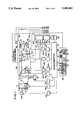
- FIG. 1 is a diagrammatic view of an embodiment of an air conditioning system for vehicles according to the present invention
- FIG. 2 is a flowchart showing a control program for the control of air-distribution
- FIG. 3 is a flowchart showing a control subroutine for the calculation of a solar radiation quantity
- FIG. 4 is a graph explanatory of the calculating operation of the subroutine shown in FIG. 4;
- FIG. 5 is a flowchart showing a control subroutine for the calculation of a solar radiation direction
- FIG. 6 is a view explanatory of the solar radiation direction with respect to the traveling direction of the vehicle
- FIG. 7 is a graph showing the relationship between the air-distribution ratio and the solar radiation direction
- FIG. 8 is a graph showing the relationship between the upper limit value of the air-distribution ratio and the set rotational speed of a blower
- FIG. 9 is a graph showing the relationship between the lower limit value of the air-distribution ratio and the set rotational speed of the blower.
- FIG. 10 is a flowchart showing another control program for the control of air-distribution and the control of the amount of air discharge.
- FIG. 11 is a graph showing the relationship between the air-distribution ratio and the solar radiation direction.
- FIG. 1 diagrammatically shows an air conditioning system for vehicles.
- the air conditioning system includes an air-flow duct 1 having an outside air intake 3 and a recirculating air intake 2 disposed at an upstream end thereofin a bifurcated fashion.
- a selecting door 4 is disposed at the junction between the two air intakes 2, 3 and is actuated by an actuator 45a driven by a driving circuit 47a so as to select between an air intake mode in which recirculated air is introduced into the air-flow duct 1 and one in which outside air is introduced thereinto.
- a blower 5 driven by a driving circuit 47b is disposed in the air-flow duct 1 adjacent to the air intakes 2, 3 for blowing air through the air-flow duct 1 in the direction of a passenger compartment.
- the duct 1 also includes an evaporator 6 disposed downstream of the blower 5.
- the evaporator 6 is connected by piping with a compressor 46 driven by a driving circuit 47c to jointly constitute a well-known refrigeration system or cycle.
- a heater core 7 is disposed downstream of the evaporator 6, and an air-mix door (a temperature control damper) 8 is disposed upstream of the heater core 7.
- the angular position of the air-mix door 8 i.e. the opening of the air-mix door 8) is regulated by an actuator 45c driven by a driving circuit 47e so that the ratio between the air flowing through the heater core 7 and the air bypassing the heater core 7 is changed to thereby control the temperature of the air discharged from the air conditioning system.
- the air-flow duct 1 has at its downstream end a defroster outlet 11, a vent outlet 9 and a lower outlet 10, which are provided in branched fashion and all open into the passenger compartment.
- Three mode doors namely, a vent door 12, a foot door 13 and a defroster door 14, are disposed adjacent to the respective outlets 9, 10 and 11.
- the mode doors 12 to 14 are controlled by an actuator 45d driven by a driving circuit 47f to establish a desired air-discharge mode.
- the vent outlet 9 has a left upper air outlet 15 opening to the left side of the passenger compartment, a right upper air outlet 16 opening to the right side of the passenger compartment, and a central upper air outlet 17 opening to the center of the passenger compartment disposed centrally between the right and left upper air outlets 16 and 15.
- a partition plate 18 is disposed at the junction between these air outlets 15 to 17 in such a way that the opening of the central upper air outlet 17 is divided into two.
- An air-distribution door 19 is disposed in front of the partition plate 18 and controlled by an actuator 45e driven by a driving circuit 47g to adjust the air-distribution ratio.
- the air conditioning system further includes a bypass duct 20 communicated with the air-flow duct 1 in such a way that one end of the bypass duct 20 opens at the portion between the evaporator 6 and the air-mix door 8 and the other end opens at the portion between the vent door 12 and the air-distribution door 19.
- a bypass door 21 is disposed at one end of the bypass duct 20 and cool air is supplied appropriately to the vent outlet 9 by means of an actuator 45b driven by a driving circuit 47d, whereby fine adjustment of the air discharge in temperature can be carried out.
- the system has a microcomputer 22 of well-known design, including a central processing unit (CPU), a read only memory (ROM), a random access memory (RAM), an input/output port (I/O), and the like (none of which are shown).
- a signal selected by a multiplexer (MPX) 23 is applied to an analog-to-digital (A/D) converter 24 for converting it into a digital form and the obtained digital signal is supplied to the microcomputer 22.
- the microcomputer 22 also receives various signals from a console panel 25, as described later on.
- the console panel 25 is equipped with a mode setter 26 for setting air-discharge modes, an intake mode setter 27 for setting the intake mode, an air-compressor (A/C) switch 28 for activating the compressor 46 in the refrigeration cycle, a blower intensity setter 29 for setting the intensity of the blower 5, an AUTO switch 30 for activating automatic air conditioning operation, and an OFF switch 31 for stopping the automatic air conditioning operation. All the switches and setters sent output signals to the microcomputer 22.
- A/C air-compressor
- the MPX 23 is connected with integral type solar radiation sensors 32 and 33 which are installed on the left and right sides of the upper surface of the vehicle's instrument panel, inside air temperature sensors 34 and 35 installed at upper and lower parts of the passenger compartment for detecting the temperatures of the upper and lower portions of the passenger compartment, an outside air temperature sensor 36 for detecting the temperature of the outside air, a duct sensor 37 for detecting the temperature of the air at the evaporator 6, and a water temperature sensor 38 for detecting the temperature of the engine coolant which supplies heat to the heater core 7, an air-distribution switch 39 for controlling the air-distribution door 19 manually, and a temperature setter 40 disposed on the console panel 25, for setting the target temperature of the inside air.
- the MPX 23 is further connected with first to fourth position sensors 41 to 44 for supplying MPX 23 with feedback signals indicating the current positions of the air-distribution door 19, the mode doors 12 to 14, the air-mix door 8, and the bypass door 21.
- the microcomputer 22 executes a control program stored therein for controlling operations of the actuator 45a for actuating selecting door 4, the blower 5, the compressor 46, the actuator 45b for actuating the bypass door 21, the actuator 45c for actuating the air-mix door 8, the actuator 45d for actuating the mode doors 12 to 14, and the actuator 45e for actuating the air-distribution door 19.
- the microcomputer 22 produces control signals on the basis of the input signals supplied from the A/D converter 24 and the console panel 25, and the control signals are applied to the driving circuits 47a to 47g.
- the microcomputer 22 starts executing the control program from step 100, and the operation moves to step 102 in which the output signals supplied from the A/D converter 24 and the console panel 25 are read in.
- step 104 After data input in step 102, a solar radiation quantity T S based on the output signals T SL , T SR of the left and right solar radiation sensors 32, 33 is calculated in step 104.
- the solar radiation quantity calculation of step 104 is conducted in accordance with the subroutine shown in FIG. 3.
- an interpolated value (T SR +T SL )/K 2 as indicated by the dotted line in FIG. 4 is calculated in step 60, based on the output signal T SL from the left solar radiation sensor 32 and the output signal T SR from the right solar radiation sensor 33.
- the interpolated value is a control value T S .
- the interpolated value is needed because the respective solar radiation sensors 32 and 33 have different directivities as indicated by the solid lines in FIG. 4 and hence the outputs from the solar radiation sensors 32, 33 have to be compensated in order to obtain a constant output irrespective of the direction of the sun.
- K 2 is a calculation constant determined such that the interpolated value has a peak which is equal to the peaks of the output signals T SL and T SR .
- the control value T S is replaced by the largest of the three values T SL , (T SR +T SL )/K 2 and T SR (steps 62 to 70).
- step 106 for calculating the solar radiation direction T D .
- This calculation is performed in accordance with the subroutine shown in FIG. 5.
- the solar radiation direction T D is represented by the angle of the sun with respect to the traveling direction of the vehicle as illustrated in FIG. 6.
- step 80 the magnitude of the output signal T SL of the left solar radiation sensor 32 is compared with the output signal T SR of the right solar radiation sensor 33. If T SL is greater than or equal to T SR , the procedure goes to step 82 in which a left side coefficient T DL is calculated as ##EQU1## where K 1 is a calculation constant.
- step 86 the solar radiation direction T D is determined from the coefficient T DL obtained in step 82 or the coefficient T DR obtained in step 84.
- step 106 the operation moves to step 108, wherein discrimination is made as to whether or not the air-discharge mode is vent mode, that is, whether or not the door 12 is open.
- step 108 When it is found that the vent outlet 9 is closed, the result in step 108 is NO and the operation moves to step 110, wherein control of the air-distribution door 19 is discontinued.
- the actuator 45e need be used less often, prolonging its service life, and, moreover, the noise made by driving the air-distribution door 19 is avoided during operation in which no air-distribution control is needed.
- the result of the discrimination in step 108 is YES when it is found that the vent mode is selected, and the operation moves to step 112, wherein discrimination is made on the basis of the position of the switch 39 for switching between manual and automatic air-distribution control for determining whether or not the automatic control mode is selected.
- the discrimination in step 112 can be carried out, for example, on the basis of the temperature of the passenger compartment and the solar radiation quantity.
- the switch 39 is set to the manual operation mode
- the result of the discrimination in step 112 is NO, and the operation moves to step 110.
- a desired air-distribution ratio can be manually set by means of a setting lever (not shown).
- step 112 if it is found in step 112 that the automatic control mode has been selected, the operation moves to step 114, wherein the range over which air-distribution control is allowed is determined in accordance with the the blower intensity setting.
- the automatic air-distribution control which will be described in detail later, is carried out in accordance with the characteristic curve illustrated in FIG. 7. Specifically, when the solar radiation direction T D is within the range between -30° and +30°, the right-to-left air-distribution ratio, namely, the ratio between the amount of air discharge from the outlet(s) to the right of the partition 18 and the amount of air discharge from the outlet(s) to the left thereof, is fixed at 1:1. As the solar radiation direction T D changes from -30° to -70°, the air-distribution to the left side of the passenger compartment increases progressively.
- the left-to-right air-distribution ratio is fixed at 5:1 (the lower limit value of ⁇ ).
- the air-distribution to the right of the passenger compartment increases progressively as the solar radiation direction T D changes from +30° to +70°.
- the left-to-right air-distribution ratio is fixed at 1:5 (the upper limit value of ⁇ ).
- the range of solar radiation directions T D between -30° to +30° is referred to as the "A zone”
- the remaining range of solar radiation directions T D is referred to as the "B zone", as illustrated in FIG. 7.
- step 114 the upper and lower limit values ⁇ and ⁇ of the air-distribution ratio are determined in response to the set rotational speed BS of the blower 5 in accordance with the characteristic curves shown in FIGS. 8 and 9, respectively.
- the range of allowable air-distribution control is set in accordance with the amount of air discharged from the blower 5.
- step 115 the air-distribution is controlled automatically in accordance with the characteristic curve shown in FIG. 7.
- the values of ⁇ and ⁇ determined in step 114 are used in step 115.
- step 116 wherein necessary control other than that of the air-distribution is executed.
- step 110 the operation moves to step 116.
- step 116 skipping the execution of steps 114 and 115.
- the interior of the passenger compartment is uniformly air-conditioned when the amount of air discharge is large, while a large change in the amount of air discharge can be suppressed during the air-distribution control when the amount of air discharged by the blower 5 is small, whereby discomfort to the occupant(s) can be reduced.
- FIG. 10 is a flowchart showing another type of control operation, in which the amount of air discharge is controlled on the basis of the air-distribution. Since the operations in steps 100 to 112 are the same as those in the flowchart shown in FIG. 2, they will not be described again here.
- step 112 When it is found in step 112 that automatic air-distribution control is selected, the operation moves from step 112 to step 120, wherein the air-distribution is automatically controlled on the basis of the solar radiation direction T D obtained by the calculation in step 106.
- the automatic air-distribution control is carried out in step 120 in accordance with the characteristic curve shown in FIG. 11. Specifically, when the solar radiation direction T D is within the range of -30° and +30°, the air-distribution ratio is fixed at 1:1. However, the air-distribution ratio changes linearly in the case when the solar radiation direction T D changes between -30° and -70°, or between 30° and 70°. In the range of the solar radiation direction T D below -70°, the lower limit value of the air-distribution ratio is fixed at 5:1 (20%). In the range of the solar radiation direction T D exceeding +70°, the upper limit value of the air-distribution ratio is fixed at 1:5 (80%). In the following description, the range of solar radiation directions T D between -50° to +50° will be referred to as the "X zone", and the remaining range of solar radiation directions T D will be referred to as the "Y zone".
- step 122 discrimination is made as to whether the solar radiation direction T D is within the X zone or within the Y zone.
- the operation moves to step 124, in which the rotational speed of the lower 5 is controlled so as to increase as the solar radiation quantity increases, whereby the amount of air discharge is corrected.
- step 126 the target temperature T 1 of the discharged air is calculated as
- step 126 the operation moves to step 126 after the execution of step 110 in the case where the determination in either step 108 or 112 is NO.
- the amount of air discharge is determined in the well-known conventional manner on the basis of the value of T 1 calculated in step 126 in accordance with the basic characteristic pattern shown by the solid line in the graph in step 128.
- a lower limit amount J of air discharge in the basic characteristic pattern is set to be equal to the amount of discharge air determined in step 124 in accordance with solar radiation quantity.
- step 130 wherein the lower limit amount J of air discharge is determined in accordance with the solar radiation quantity.
- the lower limit amount J of air discharge is fixed at a certain constant value irrespective of changes in the solar radiation quantity when the solar radiation direction T D is within the Y zone.
- the lower limit J is smaller in the case where the solar radiation direction T D is within the X zone, wherein the right-to-left air-distribution ratio is within the range of 35% and 65%, than in the case where the solar radiation direction T D is within the Y zone, wherein the right-to-left air-distribution ratio is not within the aforesaid range.
- step 132 a discharged air target temperature T 2 for the Y zone is calculated as
- K is a calculation constant, which is set to be larger value than the calculation coefficient D of formula (3). Accordingly, the discharged air target temperature T 2 for the Y zone is lower than the target temperature T 1 for the X zone.
- the correction amount of air discharge determined in step 128 on the basis of the temperature T 2 represented by the formula (4) is smaller than that used in the X zone.
- step 128 After the execution of step 128, the operation moves to step 134, wherein other control operations are carried out, and the operation advances through step 132 to other routine.
- the amount of air discharge is controlled in accordance with the air-distribution control, and the correction amount of air discharge determined in the case where the right-to-left air-distribution ratio is within the predetermined range (X zone) is smaller than that determined in the case where the right-to-left air-distribution ratio is not within the predetermined range. Therefore, it is possible to prevent an excessive amount of air from being discharged during the air-distribution control, which enhances the comfort of the occupants.
- the amount of correction is increased when the air-distribution control is carried out in the Y zone outside the X zone, an appropriate total amount of air discharge from all of the outlets can be obtained. As a result, better air conditioning can be realized than is possible with the conventional air conditioning system.
Abstract
Description
T.sub.1 =A·T.sub.d -B·T.sub.r -C·T.sub.a -D·T.sub.s +E (3)
T.sub.2 =A·Td-B·Ta-K·Ts+E (4)
Claims (13)
Applications Claiming Priority (2)
| Application Number | Priority Date | Filing Date | Title |
|---|---|---|---|
| JP2271426A JP2780060B2 (en) | 1990-10-09 | 1990-10-09 | Vehicle air conditioning controller |
| JP2-271426 | 1990-10-09 |
Publications (1)
| Publication Number | Publication Date |
|---|---|
| US5186682A true US5186682A (en) | 1993-02-16 |
Family
ID=17499870
Family Applications (1)
| Application Number | Title | Priority Date | Filing Date |
|---|---|---|---|
| US07/770,356 Expired - Fee Related US5186682A (en) | 1990-10-09 | 1991-10-03 | Air conditioning system for vehicles |
Country Status (2)
| Country | Link |
|---|---|
| US (1) | US5186682A (en) |
| JP (1) | JP2780060B2 (en) |
Cited By (31)
| Publication number | Priority date | Publication date | Assignee | Title |
|---|---|---|---|---|
| US5337802A (en) * | 1991-08-09 | 1994-08-16 | Nippondenso Co., Ltd. | Vehicle air conditioner having driver and passenger units which operate independently of one another |
| US5340021A (en) * | 1991-10-08 | 1994-08-23 | Nippondenso Co., Ltd. | Air conditioning device for vehicles |
| US5518065A (en) * | 1992-07-10 | 1996-05-21 | Mazda Motor Corporation | Control method of vehicle air-conditioning apparatus |
| US5564493A (en) * | 1993-12-22 | 1996-10-15 | Nissan Motor Co., Ltd. | Automotive air conditioning device |
| DE19543508C1 (en) * | 1995-11-22 | 1996-10-24 | Daimler Benz Ag | Automobile solar radiation sensor for passenger space temp regulation system |
| DE19543512C1 (en) * | 1995-11-22 | 1996-10-24 | Daimler Benz Ag | Motor vehicle with sun sensor |
| US5626186A (en) * | 1994-03-17 | 1997-05-06 | Nippondenso Co., Ltd. | Air conditioning apparatus for vehicles |
| EP0776777A1 (en) * | 1995-12-01 | 1997-06-04 | Mercedes-Benz Ag | Air conditioning for the interior of a vehicle dependent on solar radiation |
| US5653904A (en) * | 1996-06-18 | 1997-08-05 | Adlparvar; Sam | Defogging system for the front and rear windshields of a vehicle |
| US5676204A (en) * | 1994-07-29 | 1997-10-14 | Nippondenso Co., Ltd. | Air conditioner for use in a vehicle |
| US6202934B1 (en) * | 1999-09-03 | 2001-03-20 | Denso Corporation | Air conditioner for a vehicle having infrared ray sensor |
| US6297740B1 (en) | 1997-11-12 | 2001-10-02 | Control Devices, Inc. | Solar radiation sensor |
| DE10256866B3 (en) * | 2002-12-04 | 2004-01-08 | Daimlerchrysler Ag | Method for solar radiation-dependent air conditioning of the vehicle interior |
| US6681586B2 (en) * | 2001-10-09 | 2004-01-27 | Denso Corporation | Vehicle air conditioner with adjusting function based on sunlight amount |
| US20040217258A1 (en) * | 2003-04-30 | 2004-11-04 | Clugston P. Edward | Solar sensor including reflective element to transform the angular response |
| US20070056301A1 (en) * | 2005-09-15 | 2007-03-15 | Nissan Technical Center North America, Inc. | Automatic climate control system for vehicle |
| US20080284234A1 (en) * | 2007-05-14 | 2008-11-20 | Hall David R | Pick with a Reentrant |
| EP2332757A1 (en) * | 2008-10-10 | 2011-06-15 | Mitsubishi Heavy Industries, Ltd. | Air conditioning device for vehicle, and method and program for controlling air conditioning device for vehicle |
| US20150025738A1 (en) * | 2013-07-22 | 2015-01-22 | GM Global Technology Operations LLC | Methods and apparatus for automatic climate control in a vehicle based on clothing insulative factor |
| US9362728B2 (en) | 2011-08-01 | 2016-06-07 | SnapPower | Active cover plates |
| CN105774704A (en) * | 2015-01-08 | 2016-07-20 | 德尔福技术有限公司 | System and method to detect an unattended occupant in a vehicle and take safety countermeasures |
| US10373773B2 (en) | 2017-02-17 | 2019-08-06 | Snaprays Llc | Active cover plates |
| US10381789B2 (en) | 2011-08-01 | 2019-08-13 | Snaprays Llc | Active cover plates |
| US10381788B2 (en) | 2011-08-01 | 2019-08-13 | Snaprays Llc | Active cover plates |
| US10404045B2 (en) | 2011-08-01 | 2019-09-03 | Snaprays, Llc | Active cover plates |
| US10468834B2 (en) | 2010-09-07 | 2019-11-05 | Snaprays Llc | Illuminable wall plates |
| USD882377S1 (en) | 2011-09-06 | 2020-04-28 | Snaprays Llc | Lighted wall plate |
| US11059350B2 (en) * | 2019-03-25 | 2021-07-13 | Bayerische Motoren Werke Aktiengesellschaft | Vehicle having an air conditioning unit which has a preconditioning mode |
| US11158982B2 (en) | 2011-08-01 | 2021-10-26 | Snaprays Llc | Active cover plates |
| US11664631B2 (en) | 2011-08-01 | 2023-05-30 | Snaprays, Llc | Environment sensing active units |
| US11888301B2 (en) | 2011-08-01 | 2024-01-30 | Snaprays, Llc | Active cover plates |
Citations (3)
| Publication number | Priority date | Publication date | Assignee | Title |
|---|---|---|---|---|
| JPS57107913A (en) * | 1980-12-26 | 1982-07-05 | Diesel Kiki Co Ltd | Air conditioner for car |
| JPH01190520A (en) * | 1988-01-27 | 1989-07-31 | Diesel Kiki Co Ltd | Vehicle air-condition control device |
| US4978061A (en) * | 1987-12-21 | 1990-12-18 | Nissan Motor Company, Ltd. | Air conditioner system for automotive vehicle |
-
1990
- 1990-10-09 JP JP2271426A patent/JP2780060B2/en not_active Expired - Lifetime
-
1991
- 1991-10-03 US US07/770,356 patent/US5186682A/en not_active Expired - Fee Related
Patent Citations (3)
| Publication number | Priority date | Publication date | Assignee | Title |
|---|---|---|---|---|
| JPS57107913A (en) * | 1980-12-26 | 1982-07-05 | Diesel Kiki Co Ltd | Air conditioner for car |
| US4978061A (en) * | 1987-12-21 | 1990-12-18 | Nissan Motor Company, Ltd. | Air conditioner system for automotive vehicle |
| JPH01190520A (en) * | 1988-01-27 | 1989-07-31 | Diesel Kiki Co Ltd | Vehicle air-condition control device |
Cited By (47)
| Publication number | Priority date | Publication date | Assignee | Title |
|---|---|---|---|---|
| US5337802A (en) * | 1991-08-09 | 1994-08-16 | Nippondenso Co., Ltd. | Vehicle air conditioner having driver and passenger units which operate independently of one another |
| US5340021A (en) * | 1991-10-08 | 1994-08-23 | Nippondenso Co., Ltd. | Air conditioning device for vehicles |
| US5518065A (en) * | 1992-07-10 | 1996-05-21 | Mazda Motor Corporation | Control method of vehicle air-conditioning apparatus |
| US5564493A (en) * | 1993-12-22 | 1996-10-15 | Nissan Motor Co., Ltd. | Automotive air conditioning device |
| US5626186A (en) * | 1994-03-17 | 1997-05-06 | Nippondenso Co., Ltd. | Air conditioning apparatus for vehicles |
| US5676204A (en) * | 1994-07-29 | 1997-10-14 | Nippondenso Co., Ltd. | Air conditioner for use in a vehicle |
| DE19543508C1 (en) * | 1995-11-22 | 1996-10-24 | Daimler Benz Ag | Automobile solar radiation sensor for passenger space temp regulation system |
| DE19543512C1 (en) * | 1995-11-22 | 1996-10-24 | Daimler Benz Ag | Motor vehicle with sun sensor |
| US5857536A (en) * | 1995-11-22 | 1999-01-12 | Mercedes-Benz Ag | Sun sensing arrangement and method of arranging a sun sensor in a motor vehicle |
| EP0776777A1 (en) * | 1995-12-01 | 1997-06-04 | Mercedes-Benz Ag | Air conditioning for the interior of a vehicle dependent on solar radiation |
| US5653904A (en) * | 1996-06-18 | 1997-08-05 | Adlparvar; Sam | Defogging system for the front and rear windshields of a vehicle |
| US6297740B1 (en) | 1997-11-12 | 2001-10-02 | Control Devices, Inc. | Solar radiation sensor |
| US6202934B1 (en) * | 1999-09-03 | 2001-03-20 | Denso Corporation | Air conditioner for a vehicle having infrared ray sensor |
| US6681586B2 (en) * | 2001-10-09 | 2004-01-27 | Denso Corporation | Vehicle air conditioner with adjusting function based on sunlight amount |
| US7530234B2 (en) | 2002-12-04 | 2009-05-12 | Daimler Ag | Method for air-conditioning a vehicle interior dependent on incident sunshine |
| DE10256866B3 (en) * | 2002-12-04 | 2004-01-08 | Daimlerchrysler Ag | Method for solar radiation-dependent air conditioning of the vehicle interior |
| WO2004050398A1 (en) | 2002-12-04 | 2004-06-17 | Daimlerchrysler Ag | Method for air-conditioning a vehicle interior dependent on incident sunshine |
| US20060117772A1 (en) * | 2002-12-04 | 2006-06-08 | Rolf Roehm | Method for air-conditioning a vehicle interior dependent on incident sunshine |
| US20040217258A1 (en) * | 2003-04-30 | 2004-11-04 | Clugston P. Edward | Solar sensor including reflective element to transform the angular response |
| US20060208153A1 (en) * | 2003-04-30 | 2006-09-21 | Control Devices, Inc. | Solar sensor including reflective element to transform the angular response |
| US7235765B2 (en) | 2003-04-30 | 2007-06-26 | Control Devices, Inc. | Solar sensor including reflective element to transform the angular response |
| US20070209657A1 (en) * | 2003-04-30 | 2007-09-13 | Clugston P E Jr | Solar sensor including reflective element to transform the angular response |
| US20070056301A1 (en) * | 2005-09-15 | 2007-03-15 | Nissan Technical Center North America, Inc. | Automatic climate control system for vehicle |
| US7513439B2 (en) * | 2005-09-15 | 2009-04-07 | Nissan Technical Center North America, Inc. | Automatic climate control system for vehicle |
| US20080284234A1 (en) * | 2007-05-14 | 2008-11-20 | Hall David R | Pick with a Reentrant |
| EP2332757A1 (en) * | 2008-10-10 | 2011-06-15 | Mitsubishi Heavy Industries, Ltd. | Air conditioning device for vehicle, and method and program for controlling air conditioning device for vehicle |
| US20110160958A1 (en) * | 2008-10-10 | 2011-06-30 | Mitsubishi Heavy Industries, Ltd. | Vehicle air conditioner and control method and program for vehicle air conditioner |
| EP2332757A4 (en) * | 2008-10-10 | 2012-08-15 | Mitsubishi Heavy Ind Ltd | Air conditioning device for vehicle, and method and program for controlling air conditioning device for vehicle |
| EP2666653A1 (en) * | 2008-10-10 | 2013-11-27 | Mitsubishi Heavy Industries, Ltd. | Vehicle air conditioner and control method and program for vehicle air conditioner |
| US8744673B2 (en) * | 2008-10-10 | 2014-06-03 | Mitsubishi Heavy Industries, Ltd. | Vehicle air conditioner and control method and program for vehicle air conditioner |
| US11892153B2 (en) | 2010-09-07 | 2024-02-06 | Snaprays, Llc | Illuminable wall socket plates |
| US10886674B2 (en) | 2010-09-07 | 2021-01-05 | Snaprays, Llc | Illuminable wall socket plates |
| US10468834B2 (en) | 2010-09-07 | 2019-11-05 | Snaprays Llc | Illuminable wall plates |
| US10381789B2 (en) | 2011-08-01 | 2019-08-13 | Snaprays Llc | Active cover plates |
| US9362728B2 (en) | 2011-08-01 | 2016-06-07 | SnapPower | Active cover plates |
| US11888301B2 (en) | 2011-08-01 | 2024-01-30 | Snaprays, Llc | Active cover plates |
| US10381788B2 (en) | 2011-08-01 | 2019-08-13 | Snaprays Llc | Active cover plates |
| US10404045B2 (en) | 2011-08-01 | 2019-09-03 | Snaprays, Llc | Active cover plates |
| US11664631B2 (en) | 2011-08-01 | 2023-05-30 | Snaprays, Llc | Environment sensing active units |
| US11394157B2 (en) | 2011-08-01 | 2022-07-19 | Snaprays, Llc | Active cover plates |
| US11158982B2 (en) | 2011-08-01 | 2021-10-26 | Snaprays Llc | Active cover plates |
| USD882377S1 (en) | 2011-09-06 | 2020-04-28 | Snaprays Llc | Lighted wall plate |
| US20150025738A1 (en) * | 2013-07-22 | 2015-01-22 | GM Global Technology Operations LLC | Methods and apparatus for automatic climate control in a vehicle based on clothing insulative factor |
| CN105774704A (en) * | 2015-01-08 | 2016-07-20 | 德尔福技术有限公司 | System and method to detect an unattended occupant in a vehicle and take safety countermeasures |
| EP3042795A3 (en) * | 2015-01-08 | 2016-11-23 | Delphi Technologies, Inc. | System and method to detect an unattended occupant in a vehicle and take safety countermeasures |
| US10373773B2 (en) | 2017-02-17 | 2019-08-06 | Snaprays Llc | Active cover plates |
| US11059350B2 (en) * | 2019-03-25 | 2021-07-13 | Bayerische Motoren Werke Aktiengesellschaft | Vehicle having an air conditioning unit which has a preconditioning mode |
Also Published As
| Publication number | Publication date |
|---|---|
| JPH04146810A (en) | 1992-05-20 |
| JP2780060B2 (en) | 1998-07-23 |
Similar Documents
| Publication | Publication Date | Title |
|---|---|---|
| US5186682A (en) | Air conditioning system for vehicles | |
| US4665971A (en) | Air conditioner system for automobiles | |
| US6293339B1 (en) | Vehicle air-conditioning system with independent left/right temperature control during maximum cooling | |
| US5181553A (en) | Air conditioner system for automotive vehicle with minimum discharge temperature for rear foot outlet | |
| US6782945B1 (en) | Dual zone automatic climate control algorithm utilizing heat flux analysis | |
| US5020424A (en) | Apparatus for controlling an automotive air-conditioner | |
| US5725052A (en) | Dual zone air-conditioning system for motor vehicles with improved air flow rate | |
| US4978061A (en) | Air conditioner system for automotive vehicle | |
| JPH0141522B2 (en) | ||
| US5244035A (en) | Air-conditioner for automobiles | |
| US4962302A (en) | Control apparatus for automobile air-conditioners | |
| US5142881A (en) | Automobile air conditioning system | |
| US5056421A (en) | Automobile air-conditioner | |
| US4966011A (en) | Air-conditioning for automobiles | |
| US4953630A (en) | Apparatus for controlling an automobile air-conditioner to control defrost bleed air | |
| US5771702A (en) | Air conditioner for vehicle | |
| JP2579514B2 (en) | Vehicle air conditioning controller | |
| JP3713848B2 (en) | Air conditioner for vehicles | |
| JP2887416B2 (en) | Unbalanced solar radiation correction device for left and right independent air conditioners for vehicles | |
| JP3454189B2 (en) | Vehicle air conditioner | |
| JP3677879B2 (en) | Air conditioner for vehicles | |
| JP3481321B2 (en) | Automotive air conditioner and automotive air conditioning method | |
| JP3149229B2 (en) | Vehicle air conditioner | |
| JP2816753B2 (en) | Air conditioning balance controller for automotive air conditioner | |
| JPH04218426A (en) | Automotive air conditioner |
Legal Events
| Date | Code | Title | Description |
|---|---|---|---|
| AS | Assignment |
Owner name: ZEXEL CORPORATION A CORPORATION OF JAPAN, JAPAN Free format text: ASSIGNMENT OF ASSIGNORS INTEREST.;ASSIGNOR:IIDA, KATSUMI;REEL/FRAME:005865/0988 Effective date: 19910925 |
|
| FPAY | Fee payment |
Year of fee payment: 4 |
|
| FPAY | Fee payment |
Year of fee payment: 8 |
|
| AS | Assignment |
Owner name: BOSCH AUTOMOTIVE SYSTEMS CORPORATION, JAPAN Free format text: CHANGE OF NAME;ASSIGNOR:ZEXEL CORPORATION;REEL/FRAME:011874/0620 Effective date: 20000701 |
|
| AS | Assignment |
Owner name: ZEXEL VALEO CLIMATE CONTROL CORPORATION, JAPAN Free format text: ASSIGNMENT OF ASSIGNORS INTEREST;ASSIGNOR:BOSCH AUTOMOTIVE SYSTEMS CORPORATION;REEL/FRAME:011783/0312 Effective date: 20010115 |
|
| REMI | Maintenance fee reminder mailed | ||
| LAPS | Lapse for failure to pay maintenance fees | ||
| STCH | Information on status: patent discontinuation |
Free format text: PATENT EXPIRED DUE TO NONPAYMENT OF MAINTENANCE FEES UNDER 37 CFR 1.362 |
|
| FP | Lapsed due to failure to pay maintenance fee |
Effective date: 20050216 |