US5199773A - Desk type work station - Google Patents
Desk type work station Download PDFInfo
- Publication number
- US5199773A US5199773A US07/630,521 US63052190A US5199773A US 5199773 A US5199773 A US 5199773A US 63052190 A US63052190 A US 63052190A US 5199773 A US5199773 A US 5199773A
- Authority
- US
- United States
- Prior art keywords
- support means
- crt
- crt monitor
- guide
- spaced apart
- Prior art date
- Legal status (The legal status is an assumption and is not a legal conclusion. Google has not performed a legal analysis and makes no representation as to the accuracy of the status listed.)
- Expired - Lifetime
Links
Images


Classifications
-
- A—HUMAN NECESSITIES
- A47—FURNITURE; DOMESTIC ARTICLES OR APPLIANCES; COFFEE MILLS; SPICE MILLS; SUCTION CLEANERS IN GENERAL
- A47B—TABLES; DESKS; OFFICE FURNITURE; CABINETS; DRAWERS; GENERAL DETAILS OF FURNITURE
- A47B21/00—Tables or desks for office equipment, e.g. typewriters, keyboards
- A47B21/007—Tables or desks for office equipment, e.g. typewriters, keyboards with under-desk displays, e.g. displays being viewable through a transparent working surface of the table or desk
- A47B21/0073—Tables or desks for office equipment, e.g. typewriters, keyboards with under-desk displays, e.g. displays being viewable through a transparent working surface of the table or desk liftable above the desk top
Definitions
- This invention relates generally to desk type work stations such as those used in connection with computer type keyboards and CRT monitors and more particularly to desk type work stations when the keyboard and CRT monitor can be moved between stored and operating positions.
- This invention provides a desk type work station that has structure so that a keyboard and a CRT monitor may be stored in an out of sight location and the CRT monitor may be automatically moved upwardly and forwardly to a viewable position when desired.
- the desk type work station comprises a top panel portion having a generally flat top work surface and an opposite bottom surface.
- a pair of spaced apart pedestal means are provided for supporting the top panel portion to form an open space beneath the top panel portion and between the spaced apart pedestal means.
- An opening is formed in the top panel portion.
- a cover portion is pivotally mounted on the top panel portion and is supported in the closed position to cover the opening and has a generally flat top surface that lies in the same plane as the generally flat top work surface to form a part thereof.
- Slidable shelf means are mounted on the top panel portion to support a keyboard.
- Support means are provided for supporting a CRT monitor and are mounted for automatic upward and forward movement between a first position at which the CRT monitor is located beneath the bottom surface of the top panel portion and a second position at which at least a portion of the CRT monitor extends through the opening so that at least the screen of the CRT monitor is visible to an operator.
- the CRT monitor support means are retained in position by the slidable shelf means which, in a closed position, are also located beneath the surface of the top panel portion. When the slidable shelf means are moved to an opened position, a force is automatically applied on the CRT monitor support means to move them from the first position to the second position.
- the mounting means for the CRT monitor support means comprise two spaced apart supports mounted at fixed locations.
- First and second guide means are mounted on each of the fixedly mounted supports. At least four guide followers are mounted on the CRT monitor support means for cooperating with the first and second guide means to guide the movement of the CRT monitor support means.
- each of the first guide track means have a first linear portion extending generally in a horizontal plane and a second linear portion extending upwardly therefrom and inclined relative thereto and each of the second guide means comprises a linear portion extending in a direction inclined to the horizontal at an angle that differs from that of the second linear portion.
- each of the first guide track means extends in a linear direction that is inclined to the horizontal and the second guide means extend in a linear direction that is inclined to the horizontal at an angle that differs from that of the first guide means.
- each of the first guide means have a first linear portion that is inclined slightly from the horizontal and a second linear portion extending upwardly therefrom and inclined relative thereto, and each of the second guide means comprise a linear portion extending in a direction inclined to the horizontal at an angle that differs from the second linear portion.
- FIG. 1 is a front elevational view of a desk type work station of this invention
- FIG. 2 is a schematic illustration of one preferred embodiment of the CRT monitor support means
- FIG. 3 is an enlarged view of a portion of FIG. 1;
- FIG. 4 is a side elevational view with parts added and removed of FIG. 3;
- FIG. 5 is a schematic illustration of another preferred embodiment of the CRT monitor support means.
- FIG. 6 is a schematic illustration of a further preferred embodiment of the CRT monitor support means.
- FIG. 1 there is illustrated a desk type work station 2 of this invention comprising a top panel portion 4 having a generally flat top work surface 6 and a bottom surface 8.
- the top panel portion 4 is supported on spaced apart pedestal means 10 and 12 which are in contact with a floor 14.
- the spaced apart pedestal means 10 and 12 could be at other locations.
- a pair of spaced apart support panels 20 and 22 are secured to the bottom surface 8 by suitable means, such as by welding if the top panel portion 4 and the support panels are formed from metal.
- a support shelf 24 is slidably mounted on tracks 26 and 28 fixedly mounted on the support panels 20 and 22.
- a keyboard (not shown) is supported on the slidable support shelf 24.
- a reinforcing bar 30 extends between the support panels 20 and 22 and is secured thereto by suitable means, such as by welding.
- a first pair of facing guide means 40 and 42 are mounted on the support panels 20 and 22 by suitable means, such as by welding.
- Each of the guide means 40 and 42 has a first linear portion 44 lying generally in a horizontal plane and a second linear portion 46 extending upwardly therefrom and inclined relative thereto at an angle of about 60 degrees.
- a second pair of facing guide means 48 and 50 extend in a linear direction that is inclined relative to the horizontal at an angle of about 50 degrees.
- Each of the guide means 40, 42, 48 and 50 has a channel shape having a base 52 and integral sidewalls 54 and 56.
- CRT monitor support means 60 are provided and comprise a rectangularly shaped bottom wall portion 62, a rectangularly shaped back wall portion 64 and two triangularly shaped sidewall portions 66 and 68.
- a ventilation opening 70 is formed in the back wall portion 64.
- Two spaced apart support brackets 72 are mounted on the back wall portion 64 and two spaced apart support brackets 74 are mounted on the bottom wall portion 62 by suitable means, such as by welding.
- a roller 76 is mounted for rotation on a shaft 78, FIG. 3, secured to each support brackets 72 and 74 for rolling movement over the guide means 40, 42, 48 and 50.
- a gas-spring 80, or any other force applying means is provided for moving the CRT monitor support means 60 over the guide means 40, 42, 48 and 50.
- the gas-spring 80 is pivotally mounted on the reinforcing bar 30 by pivot means 82 and on the back wall portion 64 by pivot means 84. It is understood that the gas-spring 80 can be mounted at any desired locations and although a gas-spring is the presently preferred power source, it is understood that other power sources can be used and which may require different mountings locations.
- a CRT monitor 86 is supported on the CRT monitor support means 60.
- a rectangularly shaped opening 90 is formed in the top panel portion 4.
- a cover 92 having a rectangular shape similar to that of the opening 90 is pivotally mounted on the top panel portion 4 by pivot means 94 and has a top surface 96 and a bottom surface 98.
- a ledge 100 extends around the opening 90 and when the cover 92 is in the closed position, it is in contact with the ledge 100 so that the top surface 96 lies in the same plane as the top surface 6.
- Other means may be used to move the cover 92 such as connecting the cover 92 to the CRT monitor support means 60 for movement therewith.
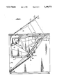
- FIG. 2 The operation of the apparatus is illustrated in FIG. 2 wherein the support shelf 24, the CRT monitor 86 and the CRT monitor support means 60 are illustrated in the closed position by the solid lines.
- the support shelf 24 has locking means 102 for holding it in the closed position.
- an integral projection 104 extends outwardly from the support shelf 24 and is in contact with the CRT monitor 86 to prevent movement thereof.
- Other types of apparatus can be used to retain the CRT monitor 86 in the closed position until it is desired to move it to the opened position.
- the support shelf 24 is unlocked and pulled out to the position illustrated by the dashed line 106.
- the movement of the support shelf 24 permits the gas-spring 80 to apply a force on the CRT monitor support means 60 to move the rollers 76 over the guide means 40, 42, 48 and 50 to an intermediate position illustrated by the dashed lines 108.
- the movement of the CRT monitor support means 60 continues until it reaches its final position illustrated by the dashed line 110.
- the CRT monitor 86 moves upwardly, it contacts the bottom surface 98 and pivots the cover 92 around the pivot means 94 so that the CRT monitor is visible to an operator.
- This mounting permits the front surface 112 to be spaced a distance from the front edge 114 of the top panel portion 4 to provide room for use of the desk when the CRT monitor is in the stored position and to be spaced a distance closer to the front edge 114 of the top panel portion 4 when in the operative position for easy viewing by the operator.
- the CRT monitor is moved upwardly and forwardly.
- FIG. 5 there is illustrated another preferred embodiment of the invention and wherein parts corresponding to those in FIGS. 1-4 have been given the same reference numerals. The only difference is in the first and second guide means.
- the first pair of facing guide means 120 are mounted on the support panels 20 and 22 and extend in a linear direction that is inclined relative to the horizontal at an angle of about 60 degrees.
- a second pair of facing guide means 122 are mounted on the support panels 20 and 22 and extend in a linear direction that is inclined relative to the horizontal at an angle of about 55 degrees.
- FIG. 5 The operation of the apparatus in FIG. 5 is similar to that in FIGS. 1-4.
- the support shelf 24, the CRT monitor 86 and the CRT monitor support means 60 are illustrated in the closed position by the solid lines.
- the CRT monitor 86 moves to the opened position, closer to the operator, illustrated by the dashed line 126.
- FIG. 6 there is illustrated a further preferred embodiment of the invention and wherein parts corresponding to those in FIG. 1 have been given the same reference numerals.
- the first difference in FIG. 6 is that the first and second guide means are shaped differently.
- the first pair of facing guide means 130 has a first linear portion 132 that is inclined slightly from the horizontal at an angle of about 20 degrees and a second linear portion 134 extending upwardly therefrom and inclined from the horizontal at an angle of about 70 degrees.
- the second pair of facing guide means 136 extend in a linear direction that is inclined relative to the horizontal at an angle of about 55 degrees.
- the second difference in FIG. 6 is in the mounting of the gas spring 80.
- One end 138 of the gas spring 80 is pivotally mounted on a support 140 secured on the back wall 142 of the desk type work station 2.
- the other end 144 is pivotally mounted on a bracket 146 depending from one side of the bottom wall portion 62.
- FIG. 6 The operation of the apparatus of FIG. 6 is similar to that in FIGS. 1-4.
- the support shelf 24, the CRT monitor 86 and the CRT monitor support means 60 are illustrated in the closed position by the solid lines.
- the CRT monitor 86 moves to the opened position, closer to the operator, illustrated by the dashed line 150.
Abstract
Description
Claims (17)
Priority Applications (1)
| Application Number | Priority Date | Filing Date | Title |
|---|---|---|---|
| US07/630,521 US5199773A (en) | 1990-12-20 | 1990-12-20 | Desk type work station |
Applications Claiming Priority (1)
| Application Number | Priority Date | Filing Date | Title |
|---|---|---|---|
| US07/630,521 US5199773A (en) | 1990-12-20 | 1990-12-20 | Desk type work station |
Publications (1)
| Publication Number | Publication Date |
|---|---|
| US5199773A true US5199773A (en) | 1993-04-06 |
Family
ID=24527513
Family Applications (1)
| Application Number | Title | Priority Date | Filing Date |
|---|---|---|---|
| US07/630,521 Expired - Lifetime US5199773A (en) | 1990-12-20 | 1990-12-20 | Desk type work station |
Country Status (1)
| Country | Link |
|---|---|
| US (1) | US5199773A (en) |
Cited By (40)
| Publication number | Priority date | Publication date | Assignee | Title |
|---|---|---|---|---|
| US5264765A (en) * | 1992-03-27 | 1993-11-23 | Pecorino Philip A | Video display screen cover |
| WO1993022953A1 (en) * | 1992-05-19 | 1993-11-25 | Nova Manufacturing & Assembly, Inc. | Adjustable monitor suspending assembly |
| US5287815A (en) * | 1992-05-07 | 1994-02-22 | Milton Gross | Computer workstation |
| US5357873A (en) * | 1992-07-22 | 1994-10-25 | Carl Hilton | Compact computer stand |
| US5368377A (en) * | 1992-11-16 | 1994-11-29 | Continental Engineering Group, Inc. | Flip-top computer workstation |
| WO1995007002A1 (en) * | 1992-03-27 | 1995-03-09 | Pecorino Philip A | Video display screen cover |
| EP0643985A2 (en) * | 1993-09-17 | 1995-03-22 | Wms Gaming, Inc. | Video monitor insertion and extraction mechanism for video game machines |
| DE4427643C1 (en) * | 1994-08-04 | 1996-02-08 | Simon Desanta | Personal computer cabinet with drop-down keyboard support |
| US5544594A (en) * | 1995-05-31 | 1996-08-13 | Nova Manufacturing & Assembly, Inc. | Adjustable monitor support assembly |
| US5651594A (en) * | 1995-05-31 | 1997-07-29 | Nova Solutions, Inc. | Work station for use with flat monitors |
| US5655822A (en) * | 1995-04-19 | 1997-08-12 | Roberts; Fay D. | Trapezoidal hidden-monitor computer desk modules and assemblies thereof |
| US5746489A (en) * | 1996-02-27 | 1998-05-05 | Moon; Jae-Nyun | Desk for computer system |
| US5758934A (en) * | 1996-08-12 | 1998-06-02 | Crown Furniture Manufacturing, Inc. | Computer monitor support |
| US5765797A (en) * | 1995-12-12 | 1998-06-16 | Greene; H. Peter | Articulated support for computers and the like |
| WO1998025501A1 (en) * | 1996-12-11 | 1998-06-18 | Emball S.A. | Worktable, in particular computer table |
| US6012788A (en) * | 1999-04-30 | 2000-01-11 | Haworth, Inc. | Laptop computer desk |
| US6092883A (en) * | 1995-05-31 | 2000-07-25 | Nova Solutions, Inc. | Work station for flat monitors |
| US6508526B2 (en) | 2000-12-20 | 2003-01-21 | George S. Reppas | Convertible bed with computer desk |
| US6588548B1 (en) | 1999-11-23 | 2003-07-08 | Load King Manufacturing, Co. | Pharmacy workstation and method of operation |
| US20030151336A1 (en) * | 2002-02-12 | 2003-08-14 | Freeman Peter C. | Computer furniture |
| US6619765B2 (en) * | 2000-08-22 | 2003-09-16 | Casper Petrus Visser | Office desk with computer workstation |
| US20040123782A1 (en) * | 2002-12-27 | 2004-07-01 | Jeffrey Korber | Integrated flat panel workstation system |
| US20040256524A1 (en) * | 2003-03-19 | 2004-12-23 | Beck Robert L. | Computer workstation with moveable monitor support |
| US20050012437A1 (en) * | 2003-07-15 | 2005-01-20 | Schulman Carl H. | Electronic component furniture construction and methods and apparatus therefor |
| US20050055770A1 (en) * | 2003-09-11 | 2005-03-17 | Reppas George S. | Convertible furniture |
| US6913332B1 (en) | 2003-01-09 | 2005-07-05 | University Of South Florida | Collapsible computer workstation |
| US20050145142A1 (en) * | 2002-12-27 | 2005-07-07 | Jeffrey Korber | Method and apparatus for retrofitting a flat panel workstation system to existing desk tops and other like structures |
| US6935247B2 (en) | 2003-01-31 | 2005-08-30 | Hni Technologies Inc. | Versatile workstation system |
| US20060174807A1 (en) * | 2005-01-26 | 2006-08-10 | Dral Joel R | Computer workstation with movable monitor support |
| WO2006105781A1 (en) * | 2005-04-07 | 2006-10-12 | P.A.U.L. GmbH Pädagogische Ausstattungs- und Lernsysteme | Desk for different uses |
| ES2267319A1 (en) * | 2002-11-24 | 2007-03-01 | Consultoria De Diseño, S.L. | Integration device for thin film transistor (TFT) screen has plate that is inclined to serve as visor of protection against luminosity of TFT screen on other plate |
| US20070157856A1 (en) * | 2006-01-11 | 2007-07-12 | Jonas Skoog | Foldable display table |
| US20080049400A1 (en) * | 2006-08-25 | 2008-02-28 | Philip Pecorino | Cover for a flat panel display |
| US20080072803A1 (en) * | 2006-09-25 | 2008-03-27 | Cbt Supply, Inc. | Convertible workstation |
| US20080072801A1 (en) * | 2006-09-25 | 2008-03-27 | Korber Jeffrey H | Convertible computer display |
| US20080290766A1 (en) * | 2003-12-12 | 2008-11-27 | Jussi Korolainen | Computer Table Element |
| US20080315733A1 (en) * | 2007-06-22 | 2008-12-25 | Terry Bosch | Modular Monitor Support Apparatus |
| US20090095868A1 (en) * | 2003-02-06 | 2009-04-16 | Ao Medical Products Sweden Aktibolag | Supporting arrangement for a presentation device |
| US20090308991A1 (en) * | 2008-06-12 | 2009-12-17 | Technical Furniture Group, Llc | Fixed flat panel monitor mounting system |
| US20100024691A1 (en) * | 2008-07-30 | 2010-02-04 | Weber Jeffrey A | Computer work station with moveable monitor support |
Citations (10)
| Publication number | Priority date | Publication date | Assignee | Title |
|---|---|---|---|---|
| US414983A (en) * | 1889-11-12 | Type-writer drop-cabinet | ||
| GB208628A (en) * | 1922-11-30 | 1923-12-27 | Henry Frederick Webb | Improvements in and relating to tables, desks or the like |
| US2516281A (en) * | 1948-04-07 | 1950-07-25 | William B Wilson | Adjustable typewriter desk |
| CH317062A (en) * | 1953-04-11 | 1956-11-15 | Hostettler Otto | Device for raising and lowering an office machine on a piece of furniture |
| EP0145410A2 (en) * | 1983-12-05 | 1985-06-19 | Hauserman Inc. | Adjustable work station and accessories therefor |
| US4590866A (en) * | 1984-02-16 | 1986-05-27 | Schairbaum Edward C | Work station with underdesk display |
| CH659370A5 (en) * | 1983-02-07 | 1987-01-30 | Franz Kuhlmann Ag | Desk for accommodating a visual display unit |
| US4640199A (en) * | 1985-03-15 | 1987-02-03 | Zigman Donald J | Mobile terminal mounting stand |
| US4669789A (en) * | 1985-03-19 | 1987-06-02 | Pemberton Peter F | Computer user's desk |
| US4766423A (en) * | 1986-01-07 | 1988-08-23 | Hitachi, Ltd. | Three-dimensional display apparatus |
-
1990
- 1990-12-20 US US07/630,521 patent/US5199773A/en not_active Expired - Lifetime
Patent Citations (10)
| Publication number | Priority date | Publication date | Assignee | Title |
|---|---|---|---|---|
| US414983A (en) * | 1889-11-12 | Type-writer drop-cabinet | ||
| GB208628A (en) * | 1922-11-30 | 1923-12-27 | Henry Frederick Webb | Improvements in and relating to tables, desks or the like |
| US2516281A (en) * | 1948-04-07 | 1950-07-25 | William B Wilson | Adjustable typewriter desk |
| CH317062A (en) * | 1953-04-11 | 1956-11-15 | Hostettler Otto | Device for raising and lowering an office machine on a piece of furniture |
| CH659370A5 (en) * | 1983-02-07 | 1987-01-30 | Franz Kuhlmann Ag | Desk for accommodating a visual display unit |
| EP0145410A2 (en) * | 1983-12-05 | 1985-06-19 | Hauserman Inc. | Adjustable work station and accessories therefor |
| US4590866A (en) * | 1984-02-16 | 1986-05-27 | Schairbaum Edward C | Work station with underdesk display |
| US4640199A (en) * | 1985-03-15 | 1987-02-03 | Zigman Donald J | Mobile terminal mounting stand |
| US4669789A (en) * | 1985-03-19 | 1987-06-02 | Pemberton Peter F | Computer user's desk |
| US4766423A (en) * | 1986-01-07 | 1988-08-23 | Hitachi, Ltd. | Three-dimensional display apparatus |
Non-Patent Citations (1)
| Title |
|---|
| Micro Center Brochure. * |
Cited By (58)
| Publication number | Priority date | Publication date | Assignee | Title |
|---|---|---|---|---|
| WO1995007002A1 (en) * | 1992-03-27 | 1995-03-09 | Pecorino Philip A | Video display screen cover |
| US5264765A (en) * | 1992-03-27 | 1993-11-23 | Pecorino Philip A | Video display screen cover |
| US5287815A (en) * | 1992-05-07 | 1994-02-22 | Milton Gross | Computer workstation |
| US5572935A (en) * | 1992-05-19 | 1996-11-12 | Nova Solutions, Inc. | Adjustable monitor suspending assembly |
| WO1993022953A1 (en) * | 1992-05-19 | 1993-11-25 | Nova Manufacturing & Assembly, Inc. | Adjustable monitor suspending assembly |
| US5410972A (en) * | 1992-05-19 | 1995-05-02 | Nova Manufacturing & Assembly, Inc. | Adjustable monitor suspending assembly |
| US5357873A (en) * | 1992-07-22 | 1994-10-25 | Carl Hilton | Compact computer stand |
| US5368377A (en) * | 1992-11-16 | 1994-11-29 | Continental Engineering Group, Inc. | Flip-top computer workstation |
| EP0643985A2 (en) * | 1993-09-17 | 1995-03-22 | Wms Gaming, Inc. | Video monitor insertion and extraction mechanism for video game machines |
| EP0643985A3 (en) * | 1993-09-17 | 1996-07-31 | Wms Gaming Inc | Video monitor insertion and extraction mechanism for video game machines. |
| DE4427643C1 (en) * | 1994-08-04 | 1996-02-08 | Simon Desanta | Personal computer cabinet with drop-down keyboard support |
| US6170926B1 (en) * | 1995-04-19 | 2001-01-09 | Fay D. Roberts | Trapezoidal hidden-monitor computer desk modules and assemblies thereof |
| US6033045A (en) * | 1995-04-19 | 2000-03-07 | Fay D. Roberts | Trapezoidal hidden-monitor computer desk modules and assemblies thereof |
| US5655822A (en) * | 1995-04-19 | 1997-08-12 | Roberts; Fay D. | Trapezoidal hidden-monitor computer desk modules and assemblies thereof |
| US5544594A (en) * | 1995-05-31 | 1996-08-13 | Nova Manufacturing & Assembly, Inc. | Adjustable monitor support assembly |
| US5651594A (en) * | 1995-05-31 | 1997-07-29 | Nova Solutions, Inc. | Work station for use with flat monitors |
| US6092883A (en) * | 1995-05-31 | 2000-07-25 | Nova Solutions, Inc. | Work station for flat monitors |
| US5765797A (en) * | 1995-12-12 | 1998-06-16 | Greene; H. Peter | Articulated support for computers and the like |
| US5746489A (en) * | 1996-02-27 | 1998-05-05 | Moon; Jae-Nyun | Desk for computer system |
| US5758934A (en) * | 1996-08-12 | 1998-06-02 | Crown Furniture Manufacturing, Inc. | Computer monitor support |
| WO1998025501A1 (en) * | 1996-12-11 | 1998-06-18 | Emball S.A. | Worktable, in particular computer table |
| US6012788A (en) * | 1999-04-30 | 2000-01-11 | Haworth, Inc. | Laptop computer desk |
| US6588548B1 (en) | 1999-11-23 | 2003-07-08 | Load King Manufacturing, Co. | Pharmacy workstation and method of operation |
| US6619765B2 (en) * | 2000-08-22 | 2003-09-16 | Casper Petrus Visser | Office desk with computer workstation |
| US6508526B2 (en) | 2000-12-20 | 2003-01-21 | George S. Reppas | Convertible bed with computer desk |
| US20030151336A1 (en) * | 2002-02-12 | 2003-08-14 | Freeman Peter C. | Computer furniture |
| ES2267319A1 (en) * | 2002-11-24 | 2007-03-01 | Consultoria De Diseño, S.L. | Integration device for thin film transistor (TFT) screen has plate that is inclined to serve as visor of protection against luminosity of TFT screen on other plate |
| US7047890B2 (en) * | 2002-12-27 | 2006-05-23 | Jeffrey Korber | Integrated flat panel workstation system |
| US20050145142A1 (en) * | 2002-12-27 | 2005-07-07 | Jeffrey Korber | Method and apparatus for retrofitting a flat panel workstation system to existing desk tops and other like structures |
| US20090151606A1 (en) * | 2002-12-27 | 2009-06-18 | Jeffrey Korber | Method and apparatus for retrofitting a flat panel workstation system to existing desk tops and other like structures |
| US20040123782A1 (en) * | 2002-12-27 | 2004-07-01 | Jeffrey Korber | Integrated flat panel workstation system |
| US20060185564A1 (en) * | 2002-12-27 | 2006-08-24 | Stengel Peter J | Integrated flat panel workstation system |
| US7509912B2 (en) | 2002-12-27 | 2009-03-31 | Technical Furniture Group, Llc | Method and system for holding and displaying an electronic flat panel display for retrofit or new installation into a work surface |
| US6913332B1 (en) | 2003-01-09 | 2005-07-05 | University Of South Florida | Collapsible computer workstation |
| US6935247B2 (en) | 2003-01-31 | 2005-08-30 | Hni Technologies Inc. | Versatile workstation system |
| US20090095868A1 (en) * | 2003-02-06 | 2009-04-16 | Ao Medical Products Sweden Aktibolag | Supporting arrangement for a presentation device |
| US20040256524A1 (en) * | 2003-03-19 | 2004-12-23 | Beck Robert L. | Computer workstation with moveable monitor support |
| US7690317B2 (en) * | 2003-03-19 | 2010-04-06 | Herman Miller, Inc. | Computer workstation with moveable monitor support |
| US20050012437A1 (en) * | 2003-07-15 | 2005-01-20 | Schulman Carl H. | Electronic component furniture construction and methods and apparatus therefor |
| US7552980B2 (en) * | 2003-07-15 | 2009-06-30 | Schulman Carl H | Electronic component furniture construction and methods and apparatus therefor |
| US20050055770A1 (en) * | 2003-09-11 | 2005-03-17 | Reppas George S. | Convertible furniture |
| US7017200B2 (en) | 2003-09-11 | 2006-03-28 | Optispace International, Inc. | Convertible furniture |
| US20080290766A1 (en) * | 2003-12-12 | 2008-11-27 | Jussi Korolainen | Computer Table Element |
| US7963234B2 (en) * | 2003-12-12 | 2011-06-21 | Hidesk Oy | Computer table element |
| US7721658B2 (en) | 2005-01-26 | 2010-05-25 | Herman Miller, Inc. | Computer workstation with movable monitor support |
| US20060174807A1 (en) * | 2005-01-26 | 2006-08-10 | Dral Joel R | Computer workstation with movable monitor support |
| WO2006105781A1 (en) * | 2005-04-07 | 2006-10-12 | P.A.U.L. GmbH Pädagogische Ausstattungs- und Lernsysteme | Desk for different uses |
| US20070157856A1 (en) * | 2006-01-11 | 2007-07-12 | Jonas Skoog | Foldable display table |
| US20080049400A1 (en) * | 2006-08-25 | 2008-02-28 | Philip Pecorino | Cover for a flat panel display |
| US20080072801A1 (en) * | 2006-09-25 | 2008-03-27 | Korber Jeffrey H | Convertible computer display |
| US20080072803A1 (en) * | 2006-09-25 | 2008-03-27 | Cbt Supply, Inc. | Convertible workstation |
| US7757612B2 (en) | 2006-09-25 | 2010-07-20 | Korber Jeffrey H | Convertible workstation |
| US7784412B2 (en) | 2006-09-25 | 2010-08-31 | Korber Jeffrey H | Convertible computer display |
| US20080315733A1 (en) * | 2007-06-22 | 2008-12-25 | Terry Bosch | Modular Monitor Support Apparatus |
| US8356779B2 (en) * | 2008-06-12 | 2013-01-22 | Stengel Jasen A | Fixed flat panel monitor mounting system |
| US20090308991A1 (en) * | 2008-06-12 | 2009-12-17 | Technical Furniture Group, Llc | Fixed flat panel monitor mounting system |
| US8371237B2 (en) | 2008-07-30 | 2013-02-12 | Herman Miller, Inc. | Computer work station with moveable monitor support |
| US20100024691A1 (en) * | 2008-07-30 | 2010-02-04 | Weber Jeffrey A | Computer work station with moveable monitor support |
Similar Documents
| Publication | Publication Date | Title |
|---|---|---|
| US5199773A (en) | Desk type work station | |
| US4313112A (en) | Computer work station assembly and mounting apparatus therefor | |
| US7111852B2 (en) | Utility cart | |
| US4755009A (en) | Work station apparatus for word processing equipment | |
| US5242217A (en) | Desk with computer work station | |
| US6168250B1 (en) | Flat panel monitor mounting assembly | |
| US4483572A (en) | Console for video display unit and detached keyboard | |
| EP0145410A2 (en) | Adjustable work station and accessories therefor | |
| US20140245932A1 (en) | Dispatch desk with focal length adjustability | |
| US5758934A (en) | Computer monitor support | |
| US5699744A (en) | Adjustable monitor support for flat monitors | |
| EP0245499A4 (en) | Computer mounting stand | |
| US20110235249A1 (en) | Work surface articulation | |
| US5564669A (en) | Base support of a display device capable of moving on a surface | |
| EP0394879A3 (en) | Electronic information equipment | |
| US5651524A (en) | Adjustable document holder for computer workstation | |
| US5413294A (en) | Platform positioned above a keyboard for use with a computer mouse | |
| US4349173A (en) | Tilt device for use with cathode ray tube display units | |
| US10597159B2 (en) | Portable electronic device holder | |
| JP2000250418A (en) | Tilting mechanism of thin display device | |
| US20040231570A1 (en) | Workstation acting as a desk or a drawing table for at least one seated user | |
| KR20090035408A (en) | Supporting device and dual display unit having the same | |
| US20060072080A1 (en) | Ceiling-mounted projection system | |
| AU5657698A (en) | Worktable, in particular computer table | |
| JP2006243270A (en) | Mounting device of image display apparatus and bed-head stand provided with this device |
Legal Events
| Date | Code | Title | Description |
|---|---|---|---|
| AS | Assignment |
Owner name: ENGINEERED DATA PRODUCTS, INC., 2550 WEST MIDWAY B Free format text: ASSIGNMENT OF ASSIGNORS INTEREST.;ASSIGNORS:PRICE, MACY J. JR.;STARKEY, DANIEL C.;REEL/FRAME:005578/0996 Effective date: 19901218 |
|
| FEPP | Fee payment procedure |
Free format text: PAYOR NUMBER ASSIGNED (ORIGINAL EVENT CODE: ASPN); ENTITY STATUS OF PATENT OWNER: SMALL ENTITY |
|
| REMI | Maintenance fee reminder mailed | ||
| FEPP | Fee payment procedure |
Free format text: PAYER NUMBER DE-ASSIGNED (ORIGINAL EVENT CODE: RMPN); ENTITY STATUS OF PATENT OWNER: SMALL ENTITY |
|
| AS | Assignment |
Owner name: EDP ACQUISITION. INC., COLORADO Free format text: ASSIGNMENT OF ASSIGNORS INTEREST;ASSIGNOR:ENGINEERED DATA PRODUCTS,LLC;REEL/FRAME:008545/0658 Effective date: 19970530 Owner name: ENGINEERED DATA PRODUCTS, LLC, COLORADO Free format text: ASSIGNMENT OF ASSIGNORS INTEREST;ASSIGNOR:ENGINEERED DATA PRODUCTS, INC.;REEL/FRAME:008545/0619 Effective date: 19970530 |
|
| AS | Assignment |
Owner name: LASALLE NATIONAL BANK, ILLINOIS Free format text: SECURITY INTEREST;ASSIGNOR:EDP ACQUISITION, INC.;REEL/FRAME:008732/0321 Effective date: 19970530 |
|
| FP | Lapsed due to failure to pay maintenance fee |
Effective date: 19970409 |
|
| AS | Assignment |
Owner name: STATE STREET BANK AND TRUST COMPANY, MASSACHUSETTS Free format text: SECURITY AGREEMENT;ASSIGNOR:ENGINEERED DATA PRODUCTS, INC. (FORMERLY KNOWN AS EDP ACQUISITION, INC.), A DELAWARE CORPORATION;REEL/FRAME:008574/0464 Effective date: 19970530 |
|
| FEPP | Fee payment procedure |
Free format text: PETITION RELATED TO MAINTENANCE FEES FILED (ORIGINAL EVENT CODE: PMFP); ENTITY STATUS OF PATENT OWNER: SMALL ENTITY |
|
| FEPP | Fee payment procedure |
Free format text: PETITION RELATED TO MAINTENANCE FEES GRANTED (ORIGINAL EVENT CODE: PMFG); ENTITY STATUS OF PATENT OWNER: SMALL ENTITY |
|
| FPAY | Fee payment |
Year of fee payment: 8 Year of fee payment: 4 |
|
| SULP | Surcharge for late payment | ||
| STCF | Information on status: patent grant |
Free format text: PATENTED CASE |
|
| FEPP | Fee payment procedure |
Free format text: PAT HLDR NO LONGER CLAIMS SMALL ENT STAT AS INDIV INVENTOR (ORIGINAL EVENT CODE: LSM1); ENTITY STATUS OF PATENT OWNER: SMALL ENTITY |
|
| PRDP | Patent reinstated due to the acceptance of a late maintenance fee |
Effective date: 19990917 |
|
| FEPP | Fee payment procedure |
Free format text: PAYOR NUMBER ASSIGNED (ORIGINAL EVENT CODE: ASPN); ENTITY STATUS OF PATENT OWNER: SMALL ENTITY |
|
| REMI | Maintenance fee reminder mailed | ||
| FEPP | Fee payment procedure |
Free format text: PAT HOLDER CLAIMS SMALL ENTITY STATUS - SMALL BUSINESS (ORIGINAL EVENT CODE: SM02); ENTITY STATUS OF PATENT OWNER: SMALL ENTITY |
|
| REFU | Refund |
Free format text: REFUND - PAYMENT OF MAINTENANCE FEE, 4TH YEAR, LARGE ENTITY (ORIGINAL EVENT CODE: R183); ENTITY STATUS OF PATENT OWNER: SMALL ENTITY |
|
| FP | Lapsed due to failure to pay maintenance fee |
Effective date: 20010406 |
|
| AS | Assignment |
Owner name: LASALLE BANK, N.A., ILLINOIS Free format text: SECURITY INTEREST;ASSIGNOR:ENGINEERED DATA PRODUCTS, INC.;REEL/FRAME:012211/0333 Effective date: 20010703 |
|
| AS | Assignment |
Owner name: STATE STREET BANK AND TRUST COMPANY, MASSACHUSETTS Free format text: SECURITY AGREEMENT;ASSIGNOR:ENGINEERED DATA PRODUCTS, INC.;REEL/FRAME:011996/0179 Effective date: 20001130 |
|
| FPAY | Fee payment |
Year of fee payment: 12 |
|
| AS | Assignment |
Owner name: ENGINEERED DATA PRODUCTS HOLDINGS, INC., COLORADO Free format text: ASSIGNMENT OF ASSIGNORS INTEREST;ASSIGNOR:ENGINEERED DATA PRODUCTS, INC.;REEL/FRAME:015841/0101 Effective date: 20041231 |
|
| AS | Assignment |
Owner name: ENGINEERED DATA PRODUCTS HOLDINGS INC., COLORADO Free format text: MERGER;ASSIGNOR:ENGINEERED DATA PRODUCTS, INC.;REEL/FRAME:015870/0864 Effective date: 20041231 Owner name: ENGINEERED DATA PRODUCTS HOLDINGS, LLC, COLORADO Free format text: MERGER;ASSIGNOR:ENGINEERED DATA PRODUCTS HOLDINGS, INC.;REEL/FRAME:016059/0831 Effective date: 20041231 |