US5200899A - Method and system for detecting the misfire of an internal combustion engine utilizing angular velocity fluctuations - Google Patents

Method and system for detecting the misfire of an internal combustion engine utilizing angular velocity fluctuations Download PDF

Info

Publication number
US5200899A
US5200899A US07/512,779 US51277990A US5200899A US 5200899 A US5200899 A US 5200899A US 51277990 A US51277990 A US 51277990A US 5200899 A US5200899 A US 5200899A
Authority
US
United States
Prior art keywords
signal
engine
torque
angular velocity
misfire
Prior art date
Legal status (The legal status is an assumption and is not a legal conclusion. Google has not performed a legal analysis and makes no representation as to the accuracy of the status listed.)
Expired - Fee Related
Application number
US07/512,779
Inventor
William B. Ribbens
Giorgio Rizzoni
Current Assignee (The listed assignees may be inaccurate. Google has not performed a legal analysis and makes no representation or warranty as to the accuracy of the list.)
MICHIGAN A CONSTITUTIONAL CORP OF MICHIGAN, University of, Regents of
University of Michigan
Original Assignee
University of Michigan
Priority date (The priority date is an assumption and is not a legal conclusion. Google has not performed a legal analysis and makes no representation as to the accuracy of the date listed.)
Filing date
Publication date
Application filed by University of Michigan filed Critical University of Michigan
Priority to US07/512,779 priority Critical patent/US5200899A/en
Assigned to REGENTS OF THE UNIVERSITY OF MICHIGAN, A CONSTITUTIONAL CORP. OF MICHIGAN reassignment REGENTS OF THE UNIVERSITY OF MICHIGAN, A CONSTITUTIONAL CORP. OF MICHIGAN ASSIGNMENT OF ASSIGNORS INTEREST. Assignors: RIBBENS, WILLIAM B., RIZZONI, GIORGIO
Priority to US07/741,338 priority patent/US5239473A/en
Priority to US07/759,397 priority patent/US5278760A/en
Priority to US08/023,342 priority patent/US5487008A/en
Application granted granted Critical
Publication of US5200899A publication Critical patent/US5200899A/en
Anticipated expiration legal-status Critical
Expired - Fee Related legal-status Critical Current

Links

Images

Classifications

    • GPHYSICS
    • G01MEASURING; TESTING
    • G01MTESTING STATIC OR DYNAMIC BALANCE OF MACHINES OR STRUCTURES; TESTING OF STRUCTURES OR APPARATUS, NOT OTHERWISE PROVIDED FOR
    • G01M15/00Testing of engines
    • G01M15/04Testing internal-combustion engines
    • G01M15/11Testing internal-combustion engines by detecting misfire
    • FMECHANICAL ENGINEERING; LIGHTING; HEATING; WEAPONS; BLASTING
    • F02COMBUSTION ENGINES; HOT-GAS OR COMBUSTION-PRODUCT ENGINE PLANTS
    • F02BINTERNAL-COMBUSTION PISTON ENGINES; COMBUSTION ENGINES IN GENERAL
    • F02B75/00Other engines
    • F02B75/02Engines characterised by their cycles, e.g. six-stroke
    • F02B2075/022Engines characterised by their cycles, e.g. six-stroke having less than six strokes per cycle
    • F02B2075/025Engines characterised by their cycles, e.g. six-stroke having less than six strokes per cycle two

Definitions

  • This invention relates to methods and systems for detecting the misfire of an internal combustion engine and, in particular, to method and system for detecting the misfire of an internal combustion engine utilizing angular velocity fluctuations of the engine.
  • Misfire is a condition in which combustion does not occur in one or more engine cycles in one or more cylinders due, for example, to absence of ignition, or misfueling.
  • unburned fuel and air are pumped into the catalyst, greatly increasing its operating temperature.
  • This problem is usually most severe under high load, high speed engine operating conditions, where even a few seconds of misfire can cause catalyst temperatures to soar above 900° C. (1650° F.), causing irreversible damage to the catalyst.
  • Even today's most advanced catalysts generally are unable to sustain continuous operation above 900° C. without damage.
  • the integrity of the exhaust emission system can best be maintained by monitoring its performance continuously on board the vehicle. It is with the intent of monitoring emission system performance that the California Air Resources Board in 1989 passed regulations which will require all new vehicles after 1994 to be equipped with on-board monitoring systems capable of detecting misfires. These proposed regulations are known as OBDII and may be followed by similar Federal EPA regulations. The proposed regulations are applicable for any misfire condition (e.g. random, continuous, equally spaced, etc.) for the purpose of identifying a malfunction.
  • the prior art discloses many methods of detecting misfire based upon measurements of torque as derived from noncontacting crankshaft angular velocity measurements. The misfire condition is detected from these torque measurements. These methods of torque measurement are well known. However, each of these methods has certain deficiencies with respect to cost effective, reliable misfire detection as required by the OBDII regulations.
  • each of U.S. Pat. Nos. 4,843,870, 4,697,561 and 4,532,592 disclose a method of measuring engine torque utilizing digital techniques to sample crankshaft angular velocity.
  • the time between successive fixed angular positions on the crankshaft is measured using a high frequency clock.
  • One sample of crankshaft angular velocity ⁇ i obtained by the relation ##EQU1## where ⁇ i and ⁇ i-1 are the crankshaft angular positions.
  • ⁇ t i time interval.
  • crankshaft angular velocity has the disadvantage of requiring electronic complexity simply to obtain a measurement (with minimum random error) of crankshaft angular velocity.
  • the clock frequency must be extremely high to have an adequate number of counts to achieve the desired sampling rate and achieve the accuracy required to measure ⁇ .
  • the accuracy of determining ⁇ i and ⁇ t i decreases with increasing RPM.
  • U.S. Pat. No. 4,550,595 discloses an analog circuit-based method of continuously estimating the instantaneous indicated torque of a four cylinder, two stroke/cycle reciprocating internal combustion engine.
  • This patent teaches a method of calculating this torque based upon noncontacting continuous time measurements of crankshaft angular velocity.
  • An exact calculation which accounts for the influence of the inertial forces associated with the reciprocating components on the crankshaft angular dynamics is also taught. There is no suggestion of using the measured torque for any cylinder by cylinder performance measurement and there is no hint of misfire monitoring.
  • U.S. Pat. No. 3,789,816 discloses a closed loop fuel control system for gasoline fueled reciprocating internal combustion engines.
  • the control system incorporates instrumentation for measuring "engine roughness” (i.e. cylinder to cylinder and cycle to cycle torque imbalance).
  • the roughness signal is obtained by electronic signal processing of crankshaft angular velocity measurements.
  • the electronic signal processing does not account for reciprocating inertia forces.
  • U.S. Pat. No. 4,292,670 discloses a method for measuring the power and/or compression balance for a diesel engine.
  • the method uses a noncontacting sensor to obtain a signal from the starter ring gear.
  • estimates are obtained of crankshaft angular velocity with a very limited sampling rate.
  • the angular velocity measurements are then used as a means of estimating the work done by the engine during power stroke without compensating for reciprocating inertial forces in the engine dynamics.
  • U.S. Pat. No. 4,197,767 discloses a method of fuel control for a gasoline fueled IC. engine during warm-up period.
  • a method of measuring "engine roughness” is provided. This method incorporates a noncontacting sensor for measuring crankshaft angular velocity.
  • Electronic signal processing generates a signal which is indicative of engine roughness.
  • reciprocating inertia compensation there is no hint of any relationship between the engine roughness signal and actual engine misfire.
  • An object of the present invention is to provide a method and system for detecting relatively low occurrence rates of engine misfires in real time in a reliable and cost effective fashion.
  • Another object of the present invention is to provide a method and system for detecting low occurrence rates of engine misfire in real time without requiring that a number of consecutive misfires occur in the same cylinder.
  • Still another object of the present invention is to provide a method and system for detecting relatively low levels of engine misfire in real time wherein single misfire events may be spaced randomly among mostly firing cycles.
  • a method for detecting the misfire of a reciprocating internal combustion engine having a plurality of reciprocating components, at least one cylinder and a crankshaft.
  • the method includes the steps of measuring the angular velocity of the crankshaft to obtain an electrical signal representation thereof and filtering the electrical signal to minimize the effects of random error and disturbances in the electrical signal to obtain a filtered angular velocity signal.
  • the method further includes the step of calculating an M-dimensional nonuniformity vector derived from the filtered angular velocity signal. M is proportional to the number of cylinders of the engine. Then an index of torque nonuniformity is computed based on the M-dimensional vector.
  • the index of torque nonuniformity represents the variation in torque from cylinder to cylinder and from cycle to cycle.
  • a statistical decision algorithm is applied to one or the other of the index of torque nonuniformity and the torque nonuniformity vector. The algorithm statistically distinguishes between a true misfire and normal cyclic variability which characterizes the combustion process in each cylinder of the engine, to thereby obtain a misfire signal.
  • Misfire can also be detected by statistical pattern recognition methods applied to the torque nonuniformity vector, and from the frequency domain equivalent of the torque signal without computing the index of torque nonuniformity.
  • the algorithm can compute the thresholds required to satisfy the misfire criteria specified by regulatory agencies, and the associated probabilities of false alarm and missed detection.
  • the preferred embodiment of the present invention in particular is configured for optimal application of statistical decision theory for reliably detecting misfire even at the lowest occurrence rates.
  • FIG. 1 is a block diagram of the method of the present invention
  • FIG. 2 is a block diagram of the system of the present invention.
  • FIG. 3 is a schematic diagram of a crankshaft position sensor for use in the present invention.
  • FIG. 4 is a block diagram of a part of the system for obtaining an analog voltage which is proportional to the angular velocity of the crankshaft;
  • FIG. 5 is a graph of reciprocating inertia torque, normalized to engine speed and reciprocating mass
  • FIG. 6 is a graph illustrating angular velocity waveforms associated with one type of misfire condition
  • FIG. 7 is a spectrum of reciprocating inertia torque
  • FIG. 8 is a spectrum of the indicated component of engine angular velocity
  • FIG. 9 is a graph of a torque waveform with samples of its extremal values
  • FIG. 10 is a graph of typical torque vector data
  • FIG. 11 is a graph of the probability density function for the random variable N under normal engine operation and misfire in one cylinder.
  • FIGS. 1 and 2 there is illustrated in FIGS. 1 and 2 the method and system for detecting the misfire of a reciprocating IC. engine utilizing angular velocity fluctuations. As indicated in FIG. 1, four possible methods are provided for such detection.
  • FIGS. 2 and 3 illustrate a crankshaft position sensor, generally indicated at 20, which generates an output signal, V, which is the primary input to an electronic signal processing unit, generally indicated at 22.
  • V an output signal
  • FIGS. 2 and 3 illustrate a crankshaft position sensor, generally indicated at 20, which generates an output signal, V, which is the primary input to an electronic signal processing unit, generally indicated at 22.
  • V an output signal
  • a variety of sensor configurations are potentially possible including magnetic induction, Hall effect, optical, etc.
  • a ferromagnetic disk generally indicated at 24, with M uniformly spaced lugs 26 is coupled magnetically to the sensor 20.
  • the disk 24 is mounted for rotation with a crankshaft 27 of an internal combustion engine.
  • the sensor 20 includes a permanent magnet 28 around which a coil 30 is wound.
  • the magnetic flux linkage varies periodically with crankshaft angle ⁇ because the magnetic coupling varies with spacing between the sensor 20 and the disk 24. This spacing is smallest whenever any lug 26 is symmetrically positioned along the center line (C L ) 32 of the crankshaft axis 34 and coil axis as shown.
  • the magnetic flux linkage for the coil 30 is smallest whenever any pair of lugs 26 are symmetrically positioned relative to the center line 32.
  • the angular period of the periodic flux linkage is ##EQU2## radians (or 360°/M degrees) where M is the number lugs 26 on the disk 24.
  • the sensor 20 As the crankshaft 27 rotates about its axis 34, the sensor 20 generates an output voltage v.(t) in accordance with Faraday's law.
  • the instantaneous frequency of the sensor voltage, ⁇ s (t) is related to the instantaneous crankshaft angular frequency ⁇ e (t) by:
  • the practical model contains a term y(t) which is a pseudo-random process associated with imperfections in the uniformity of the coupling of the sensor to the lugs 26 on the disk 24.
  • crankshaft angular velocity there are two distinct methods of obtaining the measurement of crankshaft angular velocity from the sensor output: (1) analog, and (2) digital.
  • analog the time interval between successive zero crossings at the sensor voltage ⁇ i is measured. For each such measurement, an estimate ⁇ i of angular speed is obtained. ##EQU3##
  • ⁇ i errors due to runout and imperfections in uniformity of lug spacing
  • the analog method of the present invention is preferred and is illustrated in FIG. 4.
  • the method uses an analog frequency to analog converter 36 along with a variable band pass filter 38 to obtain an analog voltage which is proportional to ⁇ i .
  • the variable filter 38 is a band pass filter whose pass band frequencies are adjusted in accordance with crankshaft average angular speed (i.e. RPM), so that the filter selectively remains constant with varying engine speed.
  • RPM crankshaft average angular speed
  • This engine speed-dependent filtering is important to the effectiveness of the misfire detection method of the present invention, as it effectively provides a signal to noise ratio which is constant at all engine speeds, and an effective signal bandwidth which is constant at all engine speeds.
  • One of the common drawbacks of other proposed methods is the inability to perform accurate detections at high speeds. The method discussed here does not suffer such limitations, because as engine speed is increased, little additional noise is introduced even though it is recognized that at high engine speeds camshaft and accessory loading add complexity to the dynamic motion of the crankshaft.
  • one of the strengths of the frequency domain approach taught herein with respect to two embodiments of the present invention is the ability to separate the frequency domain component of crankshaft speed at the firing frequency (which is due to the combustion event) from such interference events as those described above, thereby facilitating the detection of misfires at all engine speeds.
  • time domain approach Due to the optimal filtering algorithm, which eliminates the higher harmonics of the angular speed signal uniformly at all engine speeds, and owing to the fact that the misfire process generates energy only at subharmonics of the engine firing frequency, the time domain approach also achieves good detection of misfires in the presence of additional vibrations induced by such factors as camshaft loading or driveline road-induced excitation.
  • Another advantage of the present invention is the ability to distinguish individual misfiring cylinder(s). This is accomplished by means of a so-called engine cycle signal. This signal is generated once for each engine cycle (i.e. once for each two revolutions for a four-stroke/cycle engine and once per revolution for a two-stroke/cycle engine). Typically, such a signal is generated by a sensor 40 which is activated by a specific point on the engine camshaft 42, as illustrated in FIG. 2. For example, a magnetic sensor can be positioned close to a lug on the camshaft. A voltage pulse is generated each time this lug rotates past the sensor axis.
  • the successful implementation of the misfire detection method of two of the embodiments of the present invention requires algorithms which are capable of identifying the extrema of the engine torque or velocity waveform.
  • the torque waveform is derived from the analog waveform of the filtered velocity signal.
  • the present section illustrates how the detection of the extrema of the torque waveform can be accomplished either in the time, or frequency domain. Either interpretation leads to the same result: it is possible to determine the relative torque produced by each cylinder, and therefore isolate the occurrence of misfires on a cylinder-by-cylinder and cycle-by-cycle basis.
  • This section describes the preferred algorithm for the computation of the extrema of the engine torque or velocity waveform based on the measurement of crankshaft angular velocity. It is assumed that a sampled analog engine angular velocity signal, ⁇ ( ⁇ n ), is available at N samples/stroke. The minimum number of samples required to implement this algorithm is in theory equal to two samples per stroke, although the method has been empirically demonstrated to work in the case of a single sample per stroke.
  • the correction for the effects of the reciprocating motion on the angular velocity signal is based on the notion that the angular velocity signal is made up of three components: the first consists of the velocity fluctuations which occur as a consequence of the combustion process; the second is due to the unavoidable reciprocating inertia torque due to the geometry of the crank-slider mechanism, which couples the combustion produced forces to the crankshaft 27; the third is due to the superposition of any other forces exciting an oscillation of the crankshaft 27 about its axis 34, including resonances, road-induced vibration, and accessory loads.
  • the resulting discrete waveform is directly related to the net engine torque produced by the engine, and its extrema can be used to compute a torque nonuniformity index or metric as discussed hereinbelow.
  • the values of the function f( ⁇ ) may be precomputed and stored in a table for use by the processor; thus, the correction can take place simultaneously with the sampling of the analog engine speed waveform.
  • the computation of the nonuniformity metric described hereinbelow is utilized to detect to occurrence of a misfiring condition. Once such a condition is detected, the problem becomes that of isolating the faulty cylinder(s).
  • FIGURE 6 illustrates a few misfiring waveforms, corresponding respectively to: no misfire; a single cylinder misfire; and two cylinder misfires in consecutive strokes, separated by one stroke, and separated by two strokes. The figure corresponds to actual engine data, the algorithm described above converts the sampled velocity waveform shown in FIG. 6 into a 2N-vector of extrema.
  • Each of the vectors n k generates a point in 2N-dimensional euclidean space. As many points as misfire conditions can be represented in this space.
  • the pattern recognition problem consists of determining which point the observed vector of extrema is closest to (based on a normal metric), given the known misfire pattern.
  • the distance between the observation and each of the points in 2N space is represented by the shortest vector, according to the principle of orthogonal projections. Let this distance, ⁇ , be defined as follows, in vector form:
  • An equivalent result may be obtained by transforming the analog waveform to its frequency domain equivalent.
  • the frequency domain method may be even more effective in recovering the individual cylinder torque information, leading to the detection of misfires.
  • represent angular frequency (which is canonically conjugate to crank angle) and represent a crank angle to angular frequency domain transformation, such as a Discrete Fourier Transform (DFT) performed on a number of samples of the analog velocity waveform,
  • DFT Discrete Fourier Transform
  • the energy in the waveform is due to three components, as described earlier:
  • ⁇ i indicated component minus friction (combustion exciting crankshaft)
  • crankshaft e.g.: road induced, resonances, etc. . . .
  • ⁇ i and ⁇ r can by definition be obtained exactly by a DFT because of the periodic nature of the excitation in the crank angle domain. Since ⁇ r ( ⁇ ) is a periodic function of ⁇ , its Fourier series expansion is finite and can be derived exactly.
  • FIG. 7 depicts the exact spectral distribution of the reciprocating inertia component of engine torque at the crankshaft 27, for an engine with a reciprocating mass equal to M EQ , and rotating at an average speed of RPM.
  • the relative amplitude of the components is determined by the ratio of crank throw to connecting rod length, which is assumed equal to 0.25 in this plot (this is a typical value in SI engine designs).
  • the strongest periodicity of ⁇ r is in 2 ⁇ r , therefore, its effects at the firing frequency are not as pronounced as they are at the first harmonic of firing frequency.
  • the strength of the signal ⁇ r at each harmonic is a function of engine (average) RPM.
  • the signal ⁇ i is dependent on the combustion and friction processes only, and most of its energy is at the spatial frequency ⁇ f as illustrated in FIG. 8.
  • the recovery of ⁇ i ( ⁇ f ) can be accomplished by a DFT of ⁇ ( ⁇ ), where the sampling occurs synchronously with crank angle position, followed by a correction for the reciprocating inertia component at the frequency ⁇ f . It is thus sufficient to evaluate ⁇ i at the spatial frequency ⁇ f only, and to simply operate the correction for ⁇ r , at that frequency.
  • the principle which makes the misfire detection method feasible is that it is possible to obtain an estimate of the indicated torque produced by each cylinder from a measurement of the fluctuations in crankshaft angular velocity. Either the time domain or the frequency domain method is adequate to estimate individually produced cylinder torque. This result has been known for several years, as documented in the above-noted reference in the name of Rizzoni.
  • the torque nonuniformity measurement is derived from samples of the extremal values of the torque waveform as illustrated in FIG. 9. Whereas, FIG. 10 illustrates typical torque vector data.
  • the torque T( ⁇ ) is represented as a function of crankshaft angle ⁇ .
  • Each cycle represents the torque generated by a particular cylinder.
  • T( ⁇ ) By sampling T( ⁇ ) at the extremal values, the essential features of the nonuniformity are maintained. This is true because the shape of the torque waveforms between combustion events is determined by the combustion pressure as a function of crank angle and by the crank-slider geometry of the engine.
  • the crankshaft angles and associated torques at the extremal values are denoted:
  • ⁇ n crankshaft angle for relative maximum associated with cylinder n
  • ⁇ n crankshaft angle for relative minimum associated with cylinder n ##EQU5##
  • u T [1, -1, 1, -i, . . . ] is a 2N dimensional vector.
  • n is a 2N-dimensional null vector. In reality n is never a null vector owing to cyclic variability of combustion and to misfire, if present.
  • a metric n is computed for representing torque nonuniformity and for detecting misfire, which is called the torque nonuniformity index or metric. This metric is computed by evaluating the norm of a vector which indicates the deviation from ideal engine performance caused by any nonuniformity in the generation of torque.
  • the L 1 norm is normally preferred because it is more efficiently computed (it does not require square and square-root operations and can be done in integer arithmetic format, facilitating the onboard computation and misfire detection).
  • FIG. 11 is a graph of the probability density function for the random variable n under the two hypotheses.
  • H 1 misfire in one cylinder (not necessarily the same for each cycle).
  • the left distribution in FIG. 11 represents the statistics of the random fluctuations in random variable n for normal engine operation. This distribution results from normal cyclic variability in combustion.
  • the distribution on the right corresponds to the statistics in the event of one misfire in each engine cycle. The distribution is the same regardless of which cylinder misfires.
  • the cylinder number of the single misfiring can be randomly changing from cycle to cycle.
  • the detection of misfire can be based on a variety of criteria according to statistical decision theory.
  • One particularly simple test can be applied to the nonuniformity index n for each engine cycle by selecting a threshold n t midway between the mean values n H 0 for normal operation and n H 1 or misfire. ##EQU7##
  • the error rate for a typical engine is less than 0.5%.
  • the confidence level for errors at this rate is greater than 99%.

Abstract

A hybrid method and system are disclosed for the detection of internal combustion engine misfires. The method and system are capable of detecting misfires even at very low occurrence rates in real time with inexpensive analog and digital (i.e. hybrid) electronics suitable for use on-board a vehicle, thus satisfying current and proposed exhaust emission control regulations. The method and system exploit a measurement of engine crankshaft angular velocity in conjunction with hybrid electronic signal processing. Once the angular velocity signal is conditioned to minimize the effects of random error and external disturbances, four alternate computationally efficient methods may be used to extract information pertaining to individual cylinder torque productions. Two of the methods employ extremal samples of the estimated torque or velocity waveform to obtain a random torque nonuniformity index or metric. The other two methods utilize a transformation into the frequency domain. All of the methods provide an M-dimensional torque nonuniformity vector of individual cylinder performance for each individual engine cycle. The nonuniformity vector represents a compact and efficient measurement to which statistical decision theory is applied.

Description

TECHNICAL FIELD
This invention relates to methods and systems for detecting the misfire of an internal combustion engine and, in particular, to method and system for detecting the misfire of an internal combustion engine utilizing angular velocity fluctuations of the engine.
BACKGROUND ART
In recent years, automotive exhaust emission control system performance has become an important issue across the U.S. Virtually all cars sold in the U.S. from the early 1980's have been equipped with a three-way catalytic converter in the exhaust system. In order for this catalytic converter to function correctly, the vehicle is also typically equipped with a fuel control system which maintains a stoichiometric mixture (i.e. Air mass/fuel mass= 14.7).
The long-term performance of automotive exhaust emission control systems is strongly influenced by the physical condition of the catalytic converter. Unfortunately, the catalytic converter is susceptible to irreversible damage from any number of factors.
One of the most likely causes of catalyst degradation is the occurrence of engine misfire. Misfire is a condition in which combustion does not occur in one or more engine cycles in one or more cylinders due, for example, to absence of ignition, or misfueling. Under engine misfire conditions, unburned fuel and air are pumped into the catalyst, greatly increasing its operating temperature. This problem is usually most severe under high load, high speed engine operating conditions, where even a few seconds of misfire can cause catalyst temperatures to soar above 900° C. (1650° F.), causing irreversible damage to the catalyst. Even today's most advanced catalysts generally are unable to sustain continuous operation above 900° C. without damage.
Vehicle operation while misfire is present also contributes to excess emissions, especially when the misfire is present during engine warmup and the catalyst has not reached operating temperature. Obviously, misfire is also undesirable because the engine produces reduced or no torque during the misfiring cycle.
The integrity of the exhaust emission system can best be maintained by monitoring its performance continuously on board the vehicle. It is with the intent of monitoring emission system performance that the California Air Resources Board in 1989 passed regulations which will require all new vehicles after 1994 to be equipped with on-board monitoring systems capable of detecting misfires. These proposed regulations are known as OBDII and may be followed by similar Federal EPA regulations. The proposed regulations are applicable for any misfire condition (e.g. random, continuous, equally spaced, etc.) for the purpose of identifying a malfunction.
There are a variety of methods and systems for detecting misfire. These include the use of crankshaft angular velocity fluctuation, observing the change in oxygen sensor waveform pattern, enhancing the present knock sensor concept to "listen" for the absence of combustion, installation of cylinder pressure transducers, analysis of secondary ignition waveform pattern, use of temperature sensors to detect catalyst temperature during misfire, and others.
The prior art discloses many methods of detecting misfire based upon measurements of torque as derived from noncontacting crankshaft angular velocity measurements. The misfire condition is detected from these torque measurements. These methods of torque measurement are well known. However, each of these methods has certain deficiencies with respect to cost effective, reliable misfire detection as required by the OBDII regulations.
For example, each of U.S. Pat. Nos. 4,843,870, 4,697,561 and 4,532,592 disclose a method of measuring engine torque utilizing digital techniques to sample crankshaft angular velocity. The time between successive fixed angular positions on the crankshaft is measured using a high frequency clock. One sample of crankshaft angular velocity ωi obtained by the relation ##EQU1## where θi and θi-1 are the crankshaft angular positions. Δti =time interval.
One of the problems of this digital measurement of angular velocity is the random (or pseudorandom) errors involved. There are two error sources for the digital method: (1) the random variations in measurement of angular position and (2) the timing errors involved in measuring Δti. The first error source results from runout of the crankshaft gear and by variations in the magnetic coupling of the sensor to the crankshaft gear. In order to be practical for torque measurements, these angular velocity measurements must be filtered by means of a digital filter.
Thus the digital measurement of crankshaft angular velocity has the disadvantage of requiring electronic complexity simply to obtain a measurement (with minimum random error) of crankshaft angular velocity. In addition, this digital method has a limited sampling rate which is influenced by the angular separation Δθ (Δν=θii-1). The clock frequency must be extremely high to have an adequate number of counts to achieve the desired sampling rate and achieve the accuracy required to measure Δθ. The accuracy of determining θi and Δti decreases with increasing RPM.
Another deficiency in the digital method is the rather cumbersome method of dealing with engine dynamics. It has long been recognized that calculation of torque from crankshaft angular velocity measurements requires a correction for the forces associated with reciprocating components (i.e. piston, connecting rod). This is illustrated in the reference A. Rizzoni, "A Model for the Dynamics of the Internal Combustion Engine", PhD dissertation, Department of Electrical and Computer Engineering, University of Michigan, Ann Arbor, Mich., February 1986.
Still another deficiency in the references pertaining to torque nonuniformity measurements relative to misfire detection is the lack of any recognition that an index of torque nonuniformity is a random variable. There is no mention of the random nature of engine torque in the prior art references except for those published by the present inventors.
For example, U.S. Pat. No. 4,550,595 discloses an analog circuit-based method of continuously estimating the instantaneous indicated torque of a four cylinder, two stroke/cycle reciprocating internal combustion engine. This patent teaches a method of calculating this torque based upon noncontacting continuous time measurements of crankshaft angular velocity. An exact calculation which accounts for the influence of the inertial forces associated with the reciprocating components on the crankshaft angular dynamics is also taught. There is no suggestion of using the measured torque for any cylinder by cylinder performance measurement and there is no hint of misfire monitoring.
U.S. Pat. No. 3,789,816 discloses a closed loop fuel control system for gasoline fueled reciprocating internal combustion engines. The control system incorporates instrumentation for measuring "engine roughness" (i.e. cylinder to cylinder and cycle to cycle torque imbalance). The roughness signal is obtained by electronic signal processing of crankshaft angular velocity measurements. The electronic signal processing does not account for reciprocating inertia forces.
U.S. Pat. No. 4,292,670 discloses a method for measuring the power and/or compression balance for a diesel engine. The method uses a noncontacting sensor to obtain a signal from the starter ring gear. Using a digital method, estimates are obtained of crankshaft angular velocity with a very limited sampling rate. The angular velocity measurements are then used as a means of estimating the work done by the engine during power stroke without compensating for reciprocating inertial forces in the engine dynamics.
U.S. Pat. No. 4,197,767 discloses a method of fuel control for a gasoline fueled IC. engine during warm-up period. A method of measuring "engine roughness" is provided. This method incorporates a noncontacting sensor for measuring crankshaft angular velocity. Electronic signal processing generates a signal which is indicative of engine roughness. However, there is no teaching of reciprocating inertia compensation. Furthermore, there is no hint of any relationship between the engine roughness signal and actual engine misfire.
SUMMARY OF THE INVENTION
An object of the present invention is to provide a method and system for detecting relatively low occurrence rates of engine misfires in real time in a reliable and cost effective fashion.
Another object of the present invention is to provide a method and system for detecting low occurrence rates of engine misfire in real time without requiring that a number of consecutive misfires occur in the same cylinder.
Still another object of the present invention is to provide a method and system for detecting relatively low levels of engine misfire in real time wherein single misfire events may be spaced randomly among mostly firing cycles.
In carrying out the above objects and other objects of the present invention, a method is provided for detecting the misfire of a reciprocating internal combustion engine having a plurality of reciprocating components, at least one cylinder and a crankshaft. The method includes the steps of measuring the angular velocity of the crankshaft to obtain an electrical signal representation thereof and filtering the electrical signal to minimize the effects of random error and disturbances in the electrical signal to obtain a filtered angular velocity signal. The method further includes the step of calculating an M-dimensional nonuniformity vector derived from the filtered angular velocity signal. M is proportional to the number of cylinders of the engine. Then an index of torque nonuniformity is computed based on the M-dimensional vector. The index of torque nonuniformity represents the variation in torque from cylinder to cylinder and from cycle to cycle. Finally, a statistical decision algorithm is applied to one or the other of the index of torque nonuniformity and the torque nonuniformity vector. The algorithm statistically distinguishes between a true misfire and normal cyclic variability which characterizes the combustion process in each cylinder of the engine, to thereby obtain a misfire signal.
Misfire can also be detected by statistical pattern recognition methods applied to the torque nonuniformity vector, and from the frequency domain equivalent of the torque signal without computing the index of torque nonuniformity.
Further, the algorithm can compute the thresholds required to satisfy the misfire criteria specified by regulatory agencies, and the associated probabilities of false alarm and missed detection. The preferred embodiment of the present invention in particular is configured for optimal application of statistical decision theory for reliably detecting misfire even at the lowest occurrence rates.
Also provided is a system for carrying out each of the method steps.
Four possible embodiments are provided for carrying out the calculating step.
The objects, features and advantages of the present invention are readily apparent from the following detailed description of the best mode for carrying out the invention when taken in connection with the accompanying drawings.
BRIEF DESCRIPTION OF THE DRAWINGS
FIG. 1 is a block diagram of the method of the present invention;
FIG. 2 is a block diagram of the system of the present invention;
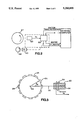
FIG. 3 is a schematic diagram of a crankshaft position sensor for use in the present invention;
FIG. 4 is a block diagram of a part of the system for obtaining an analog voltage which is proportional to the angular velocity of the crankshaft;
FIG. 5 is a graph of reciprocating inertia torque, normalized to engine speed and reciprocating mass;
FIG. 6 is a graph illustrating angular velocity waveforms associated with one type of misfire condition;
FIG. 7 is a spectrum of reciprocating inertia torque;
FIG. 8 is a spectrum of the indicated component of engine angular velocity;
FIG. 9 is a graph of a torque waveform with samples of its extremal values;
FIG. 10 is a graph of typical torque vector data; and
FIG. 11 is a graph of the probability density function for the random variable N under normal engine operation and misfire in one cylinder.
BRIEF DESCRIPTION OF THE BEST MODE
Referring now to the drawing figures, there is illustrated in FIGS. 1 and 2 the method and system for detecting the misfire of a reciprocating IC. engine utilizing angular velocity fluctuations. As indicated in FIG. 1, four possible methods are provided for such detection.
FIGS. 2 and 3 illustrate a crankshaft position sensor, generally indicated at 20, which generates an output signal, V,, which is the primary input to an electronic signal processing unit, generally indicated at 22. A variety of sensor configurations are potentially possible including magnetic induction, Hall effect, optical, etc.
In the embodiment of FIG. 3, a ferromagnetic disk, generally indicated at 24, with M uniformly spaced lugs 26 is coupled magnetically to the sensor 20. The disk 24 is mounted for rotation with a crankshaft 27 of an internal combustion engine.
In this embodiment of the sensor 20, the sensor 20 includes a permanent magnet 28 around which a coil 30 is wound. The magnetic flux linkage varies periodically with crankshaft angle θ because the magnetic coupling varies with spacing between the sensor 20 and the disk 24. This spacing is smallest whenever any lug 26 is symmetrically positioned along the center line (CL) 32 of the crankshaft axis 34 and coil axis as shown. The magnetic flux linkage for the coil 30 is smallest whenever any pair of lugs 26 are symmetrically positioned relative to the center line 32. The angular period of the periodic flux linkage is ##EQU2## radians (or 360°/M degrees) where M is the number lugs 26 on the disk 24.
As the crankshaft 27 rotates about its axis 34, the sensor 20 generates an output voltage v.(t) in accordance with Faraday's law. The instantaneous frequency of the sensor voltage, ωs (t) is related to the instantaneous crankshaft angular frequency ωe (t) by:
ω.sub.s (t)=Mω.sub.s (t)                       (ideal model)
ω.sub.s (t)=Mω.sub.o (t)+y(t)                  (practical model)
The practical model contains a term y(t) which is a pseudo-random process associated with imperfections in the uniformity of the coupling of the sensor to the lugs 26 on the disk 24.
There are two distinct methods of obtaining the measurement of crankshaft angular velocity from the sensor output: (1) analog, and (2) digital. In one digital method, the time interval between successive zero crossings at the sensor voltage τi is measured. For each such measurement, an estimate ωi of angular speed is obtained. ##EQU3##
In the practical model, errors δθi and δτi occur due respectively to:
δθi =errors due to runout and imperfections in uniformity of lug spacing
δτi =time interval errors
In the digital method, there are three error sources in each estimate of ωi. The timing errors associated with measuring τi, the errors in τθi due to imperfections in tooth to tooth spacing and/or magnetic coupling and the errors in δθi due to runout can be reduced by digital filtering of ωi. However, the runout error generates an error signal the spectrum of which overlaps the spectrum of the engine angular velocity signal during misfires and, in general, cannot be separated from measurements of ωi.
The analog method of the present invention is preferred and is illustrated in FIG. 4. The method uses an analog frequency to analog converter 36 along with a variable band pass filter 38 to obtain an analog voltage which is proportional to ωi.
The variable filter 38 is a band pass filter whose pass band frequencies are adjusted in accordance with crankshaft average angular speed (i.e. RPM), so that the filter selectively remains constant with varying engine speed. This engine speed-dependent filtering is important to the effectiveness of the misfire detection method of the present invention, as it effectively provides a signal to noise ratio which is constant at all engine speeds, and an effective signal bandwidth which is constant at all engine speeds. One of the common drawbacks of other proposed methods is the inability to perform accurate detections at high speeds. The method discussed here does not suffer such limitations, because as engine speed is increased, little additional noise is introduced even though it is recognized that at high engine speeds camshaft and accessory loading add complexity to the dynamic motion of the crankshaft. However, one of the strengths of the frequency domain approach taught herein with respect to two embodiments of the present invention is the ability to separate the frequency domain component of crankshaft speed at the firing frequency (which is due to the combustion event) from such interference events as those described above, thereby facilitating the detection of misfires at all engine speeds.
The same is also accomplished in the time domain approach, also taught herein. Due to the optimal filtering algorithm, which eliminates the higher harmonics of the angular speed signal uniformly at all engine speeds, and owing to the fact that the misfire process generates energy only at subharmonics of the engine firing frequency, the time domain approach also achieves good detection of misfires in the presence of additional vibrations induced by such factors as camshaft loading or driveline road-induced excitation.
Another advantage of the present invention is the ability to distinguish individual misfiring cylinder(s). This is accomplished by means of a so-called engine cycle signal. This signal is generated once for each engine cycle (i.e. once for each two revolutions for a four-stroke/cycle engine and once per revolution for a two-stroke/cycle engine). Typically, such a signal is generated by a sensor 40 which is activated by a specific point on the engine camshaft 42, as illustrated in FIG. 2. For example, a magnetic sensor can be positioned close to a lug on the camshaft. A voltage pulse is generated each time this lug rotates past the sensor axis.
Detection of Torque Extrema
The successful implementation of the misfire detection method of two of the embodiments of the present invention requires algorithms which are capable of identifying the extrema of the engine torque or velocity waveform. The torque waveform is derived from the analog waveform of the filtered velocity signal. The present section illustrates how the detection of the extrema of the torque waveform can be accomplished either in the time, or frequency domain. Either interpretation leads to the same result: it is possible to determine the relative torque produced by each cylinder, and therefore isolate the occurrence of misfires on a cylinder-by-cylinder and cycle-by-cycle basis.
Method 1: Time Domain
This section describes the preferred algorithm for the computation of the extrema of the engine torque or velocity waveform based on the measurement of crankshaft angular velocity. It is assumed that a sampled analog engine angular velocity signal, ω(θn), is available at N samples/stroke. The minimum number of samples required to implement this algorithm is in theory equal to two samples per stroke, although the method has been empirically demonstrated to work in the case of a single sample per stroke.
As noted in the above-noted reference in the name of G. Rizzoni, in order to compute the torque waveform from the angular velocity waveform, one needs to account for the effect of the reciprocating inertia torque as illustrated in FIG. 5 (i.e. that caused by the reciprocating motion of the piston in the cylinder). The correction for the effects of the reciprocating motion on the angular velocity signal is based on the notion that the angular velocity signal is made up of three components: the first consists of the velocity fluctuations which occur as a consequence of the combustion process; the second is due to the unavoidable reciprocating inertia torque due to the geometry of the crank-slider mechanism, which couples the combustion produced forces to the crankshaft 27; the third is due to the superposition of any other forces exciting an oscillation of the crankshaft 27 about its axis 34, including resonances, road-induced vibration, and accessory loads. The road induced disturbance term has been experimentally shown to be negligible in most cases, due to the elastic coupling which typically exists between the crankshaft 27 and the driveshaft (either by means of a clutch plate, or by the torque converter fluid). The net effect of all these components is viewed as consisting of essentially random noise. The following expressions illustrate this subdivision:
ω(θ.sub.n)=ω.sub.i (θ.sub.n)+ω.sub.r (θ.sub.n)+ε(θ.sub.n)
In order to correct for the effects of the reciprocating inertia torque on the angular velocity signal, it is necessary to subtract the term ωr (θ) from the measured angular velocity. As illustrated in the reference G. Rizzoni "A Model for the Dynamics of the Internal Combustion Engine", PhD dissertation, Department of Electrical and Computer Engineering, University of Michigan, Ann Arbor, Mich., February 1986, such a correction term amounts to the product of a known function of crank angle f(θ), times the square of the average engine RPM. The function f(θ) is determined by the geometry of the reciprocating assembly, and can be precomputed for any engine class given. An approximate expression for the reciprocating inertia torque, normalized with respect to engine speed and reciprocating mass, is given by equation below for a four cylinder in-line engine configuration; corresponding expressions may be obtained for six and eight-cylinder engines in various configurations. The approximation used below is adequate for the purpose of estimating the net engine torque applied at the crankshaft throw. ##EQU4## where R is the crank throw, L is the connecting rod length, MEQ is the equivalent reciprocating mass and θ is the crank angle.
Once the correction for reciprocating inertia has been effected, the resulting discrete waveform is directly related to the net engine torque produced by the engine, and its extrema can be used to compute a torque nonuniformity index or metric as discussed hereinbelow.
The values of the function f(θ) may be precomputed and stored in a table for use by the processor; thus, the correction can take place simultaneously with the sampling of the analog engine speed waveform.
An M-dimensional vector of torque extrema also discussed and defined hereinbelow,wherein M number of cylinders,
n=T-T.sub.av u
may be used to isolate the cylinder(s) responsible for the misfiring condition very effectively, upon application of some simple pattern recognition methods. The computation of the nonuniformity metric described hereinbelow is utilized to detect to occurrence of a misfiring condition. Once such a condition is detected, the problem becomes that of isolating the faulty cylinder(s).
Each misfire pattern is characterized by a specific vector nk, where the index k corresponds to the type of misfiring pattern. For example, k=0 might correspond to the condition "no misfire", k=1 to "misfire in cylinder No. 1", k=3,1 to "misfire in cylinders 3 and 1". Thus, each misfire condition is characterized by a unique vector signature. FIGURE 6 illustrates a few misfiring waveforms, corresponding respectively to: no misfire; a single cylinder misfire; and two cylinder misfires in consecutive strokes, separated by one stroke, and separated by two strokes. The figure corresponds to actual engine data, the algorithm described above converts the sampled velocity waveform shown in FIG. 6 into a 2N-vector of extrema.
Each of the vectors nk generates a point in 2N-dimensional euclidean space. As many points as misfire conditions can be represented in this space. The pattern recognition problem consists of determining which point the observed vector of extrema is closest to (based on a normal metric), given the known misfire pattern. The distance between the observation and each of the points in 2N space is represented by the shortest vector, according to the principle of orthogonal projections. Let this distance, δ, be defined as follows, in vector form:
δ.sup.k =n.sup.k -n
where is the observed vector of extrema corresponding to a specific engine cycle. Then the problem of isolating the misfiring cylinder is reduced to computing a norm of δk (any Lp norm will suffice), and finding the minimum value: min{// δk // }. This minimum indicates the "nearest neighbor", and therefore isolates the cylinder(s) which are the most probable cause of misfire. Experiments performed on production vehicles have verified that if this nearest neighbor classification is executed on the basis of a single cycle of engine velocity data, the correct classification is made with an error rate of three incorrect classifications in one thousand cycles. If the average of two consecutive cycles is computed, our experiments indicated zero errors over a sample space of 5,000 cycles.
METHOD 2: Frequency Domain
An equivalent result may be obtained by transforming the analog waveform to its frequency domain equivalent. The frequency domain method may be even more effective in recovering the individual cylinder torque information, leading to the detection of misfires.
Let λ represent angular frequency (which is canonically conjugate to crank angle) and represent a crank angle to angular frequency domain transformation, such as a Discrete Fourier Transform (DFT) performed on a number of samples of the analog velocity waveform,
i.e.,  (f(θ))= (λ).
Then at where the latter represents the firing frequency of the engine, the energy in the waveform is due to three components, as described earlier:
ω(θ)=ω.sub.i (θ)+ω.sub.r (θ)+ε(θ)
where
ωi =indicated component minus friction (combustion exciting crankshaft)
ωr =reciprocating component
ε=error due to random and nonrandom excitations of the crankshaft (e.g.: road induced, resonances, etc. . . )
Let the frequency domain equivalents of the above be Ωi, Ωr, and E, respectively.
The spectrum of Ωi and Ωr can by definition be obtained exactly by a DFT because of the periodic nature of the excitation in the crank angle domain. Since ωr (θ) is a periodic function of θ, its Fourier series expansion is finite and can be derived exactly.
FIG. 7 depicts the exact spectral distribution of the reciprocating inertia component of engine torque at the crankshaft 27, for an engine with a reciprocating mass equal to MEQ, and rotating at an average speed of RPM. The relative amplitude of the components is determined by the ratio of crank throw to connecting rod length, which is assumed equal to 0.25 in this plot (this is a typical value in SI engine designs).
Due to the geometry of the reciprocating assembly, the strongest periodicity of ωr is in 2λr, therefore, its effects at the firing frequency are not as pronounced as they are at the first harmonic of firing frequency. The strength of the signal Ωr at each harmonic is a function of engine (average) RPM.
By contrast, the signal Ωi is dependent on the combustion and friction processes only, and most of its energy is at the spatial frequency λf as illustrated in FIG. 8.
The process (λ)= (f(θ)) is considered a noise process. Its spectrum consists of the super-position of signals due to two effects: i) random vibrations propagating to the structure as a consequence of external excitation; ii) structural resonances excited by the combustion process (e.g.: the influence of the dynamic motion of the valves). Such processes are not periodic in terms of engine revolution, but exhibit an overall behavior which can be characterized as additive random noise at the frequency λf. Thus, the energy released during the combustion process is highly correlated with the component of Ωi at λr.
The recovery of Ωif) can be accomplished by a DFT of ω(θ), where the sampling occurs synchronously with crank angle position, followed by a correction for the reciprocating inertia component at the frequency λf. It is thus sufficient to evaluate Ωi at the spatial frequency λf only, and to simply operate the correction for Ωr, at that frequency.
Torque Estimation
The principle which makes the misfire detection method feasible is that it is possible to obtain an estimate of the indicated torque produced by each cylinder from a measurement of the fluctuations in crankshaft angular velocity. Either the time domain or the frequency domain method is adequate to estimate individually produced cylinder torque. This result has been known for several years, as documented in the above-noted reference in the name of Rizzoni.
The torque nonuniformity measurement is derived from samples of the extremal values of the torque waveform as illustrated in FIG. 9. Whereas, FIG. 10 illustrates typical torque vector data.
In FIG. 9, the torque T(♭) is represented as a function of crankshaft angle θ. Each cycle represents the torque generated by a particular cylinder. By sampling T(θ) at the extremal values, the essential features of the nonuniformity are maintained. This is true because the shape of the torque waveforms between combustion events is determined by the combustion pressure as a function of crank angle and by the crank-slider geometry of the engine. The crankshaft angles and associated torques at the extremal values are denoted:
θn =crankshaft angle for relative maximum associated with cylinder n
θn =crankshaft angle for relative minimum associated with cylinder n ##EQU5## These values are obtained for each engine cycle and an M-dimensional vector is computed, where M =2N in the preferred embodiment and where the superscript T denotes the transpose of the vector.
T.sup.T =[T.sub.1, T.sub.1, . . . T.sub.n, T.sub.n ].
The average value for the 2N components Tav is then found. ##EQU6## The a 2N-dimensional vector representing torque nonuniformity is computed.
n=T-T.sub.av u.
where uT =[1, -1, 1, -i, . . . ] is a 2N dimensional vector.
If the torque produced by the engine during a given cycle were absolutely uniform, then n would be a 2N-dimensional null vector. In reality n is never a null vector owing to cyclic variability of combustion and to misfire, if present. A metric n is computed for representing torque nonuniformity and for detecting misfire, which is called the torque nonuniformity index or metric. This metric is computed by evaluating the norm of a vector which indicates the deviation from ideal engine performance caused by any nonuniformity in the generation of torque.
Any Lp norm is adequate for the purpose of detecting the presence of a misfire; the two most common choices are:
n=∥n∥.sub.1                              L.sub.1 norm
n=∥n∥.sub.2                              L.sub.2 norm
Although either norm of will suffice for misfire detection, the L1 norm is normally preferred because it is more efficiently computed (it does not require square and square-root operations and can be done in integer arithmetic format, facilitating the onboard computation and misfire detection).
Detection of misfire is done on a statistical hypothesis testing basis. FIG. 11 is a graph of the probability density function for the random variable n under the two hypotheses.
H0 : normal engine operation
H1 : misfire in one cylinder (not necessarily the same for each cycle).
The left distribution in FIG. 11 represents the statistics of the random fluctuations in random variable n for normal engine operation. This distribution results from normal cyclic variability in combustion. The distribution on the right corresponds to the statistics in the event of one misfire in each engine cycle. The distribution is the same regardless of which cylinder misfires. The cylinder number of the single misfiring can be randomly changing from cycle to cycle.
The detection of misfire can be based on a variety of criteria according to statistical decision theory. One particularly simple test can be applied to the nonuniformity index n for each engine cycle by selecting a threshold nt midway between the mean values nH 0 for normal operation and nH 1 or misfire. ##EQU7##
This particular choice of thresholds corresponds to assigning equal costs to false alarms and missed detections.
The following criterion for misfire detection is applied in the present embodiment.
n>nt →misfire
n<nt →normal operation.
There are two types of errors made by such a method:
1. n<n for a misfiring cycle
2. n>nt for a normal cycle.
The probability for such errors is: ##EQU8##
From actual experimental data, the error rate for a typical engine is less than 0.5%. The confidence level for errors at this rate is greater than 99%.
The invention has been described in an illustrative manner and, it is to be understood that, the terminology which has been used is intended to be in the nature of words of description rather than of limitation.
Obviously, many modifications and variations of the present invention are possible in light of the above teachings. It is, therefore, to be understood that, within the scope of the appended claims, the invention may be practiced otherwise than as specifically described.

Claims (42)

What is claimed is:
1. A method for detecting the misfire of a reciprocating internal combustion engine having a plurality of reciprocating components, at least one cylinder and a crankshaft, the method comprising the steps of:
measuring the angular velocity of the crankshaft to obtain an electrical signal representation thereof;
filtering the electrical signal to minimize the effects of random error and disturbances in the electrical signal to obtain a filtered angular velocity signal;
calculating an M-dimensional torque nonuniformity vector derived from the filtered angular velocity signal, where M is proportional to the number of cylinders of the engine; and
applying a statistical decision algorithm to the torque nonuniformity vector, which algorithm statistically distinguishes between a true misfire and normal cyclic variability which characterizes the combustion process in each cylinder of the engine, to thereby obtain a misfire signal.
2. A method for detecting the misfire of a reciprocating internal combustion engine having a plurality of reciprocating components, at least one cylinder and a crankshaft, the method comprising the steps of:
measuring the angular velocity of the crankshaft to obtain an electrical signal representation thereof;
filtering the electrical signal to minimize the effects of random error and disturbances in the electrical signal to obtain a filtered angular velocity signal;
calculating an M-dimensional torque nonuniformity vector derived from the filtered angular velocity signal, where M is proportional to the number of cylinders of the engine;
computing an index of torque nonuniformity based on the M-dimensional vector, the index of torque nonuniformity representing the variation in torque from cylinder to cylinder and from cycle to cycle; and
applying a statistical decision algorithm to one of the torque nonuniformity vector and the index of torque nonuniformity, which algorithm statistically distinguishes between a true misfire and normal cyclic variability which characterizes the combustion process in each cylinder of the engine, to thereby obtain a misfire signal.
3. The method as claimed in claim 1 or claim 2 wherein the step of measuring includes the step of obtaining a signal from a sensor coupled to the crankshaft whose instantaneous frequency is proportional to the instantaneous crankshaft angular velocity.
4. The method as claimed in claim 3 wherein the step of measuring is at least partially performed by an analog circuit to obtain an analog of the angular velocity signal.
5. The method as claimed in claim 4 further comprising the step of converting the analog of the angular velocity signal to an analog voltage signal which is a function of the frequency of the analog velocity signal.
6. The method as claimed in claim 5 wherein the step of filtering is performed on the analog voltage signal.
7. The method as claimed in claim 1 or claim 2 further comprising the step of generating an average angular velocity signal which is proportional to the average angular velocity of the crankshaft.
8. The method as claimed in claim 7 wherein the step of filtering is accomplished with a variable band pass filter having a variable band determined as a function of average angular velocity to preserve the information required to detect misfires independent of r.p.m..
9. The method as claimed in claim 1 or claim 2 wherein a statistical pattern recognition algorithm is used for detecting at least one misfire cylinder based on the misfire signal.
10. The method as claimed in claim 1 or claim 2 wherein the step of calculating includes the step of estimating indicated torque provided by each cylinder based upon said crankshaft angular velocity in which the appropriate engine dynamics, including reciprocating inertia forces, are taken into account to obtain an indicated torque signal.
11. The method of claim 10 wherein the step of calculating includes the step of determining the extrema of the indicated torque signal which extrema comprise the elements of the M-dimensional nonuniformity vector.
12. The method as claimed in claim 10 wherein the indicated torque signal has an analog waveform and wherein the step of calculating includes the step of transforming the analog waveform of at least a portion of the indicated torque signal to a frequency domain equivalent for each cylinder within each engine cycle, which frequency domain equivalents comprise the elements of the M-dimensional nonuniformity vector.
13. The method as claimed in claim 1 or claim 2 wherein the step of calculating includes the step of determining the extrema of the filtered angular velocity signal, which extrema comprise the elements of the M-dimensional nonuniformity vector.
14. The method as claimed in claim 1 or claim 2 wherein the filtered angular velocity signal has an analog waveform and wherein the step of calculating includes the step of transforming the analog waveform of at least a portion of the filtered analog velocity signal to a frequency domain equivalent.
15. The method as claimed in claim 13 further comprising the steps of determining at least one frequency related to a firing frequency of the engine and determining the portion of the frequency domain equivalent which is due to combustion energy effectively exciting the crankshaft at the at least one frequency to thereby account for the torque attributable to the reciprocating forces.
16. The method as claimed in claim 2 wherein the step of applying includes the step of comparing the index of torque nonuniformity with a threshold value to obtain the misfire signal.
17. The method as claimed in claim 16 wherein whenever the index of torque nonuniformity exceeds the threshold value for any given engine cycle a misfire is declared, otherwise normal operation is determined for the given engine cycle.
18. The method as claimed in claim 17 wherein the threshold value is predetermined based on a predetermined statistical measure of the index of torque nonuniformity for both normal engine operation and an engine misfire.
19. The method of claim 16 or claim 18 further comprising the steps of generating an engine cycle signal as a function of the particular cycle of the engine and identifying at least one misfiring cylinder as a function of the engine cycle signal and the nonuniformity vector.
20. The method as claimed in claim 1 or claim 2 further comprising the steps of generating an engine cycle signal as a function of the particular cycle of the engine and identifying at least one misfiring cylinder as a function of the misfire signal and the nonuniformity vector.
21. The method as claimed in claim 1 or claim 2 further comprising the step of detecting which of the cylinders has misfired based on the nonuniformity vector.
22. A system for detecting the misfire of a reciprocating internal combustion engine having a plurality of reciprocating components, at least one cylinder and a crankshaft, the system comprising:
means for filtering the electrical signal to minimize the effects of random error and disturbances in the electrical signal to obtain a filtered angular velocity signal;
means for calculating an M-dimensional torque nonuniformity vector derived from the filtered angular velocity signal, where M is proportional to the number of cylinders of the engine; and
means for applying a statistical decision algorithm to the torque nonuniformity vector, which algorithm statistically distinguishes between a true misfire and normal cyclic variability which characterizes the combustion process in each cylinder of the engine, to thereby obtain a misfire signal.
23. A system for detecting the misfire of a reciprocating internal combustion engine, having a plurality of reciprocating components, at least one cylinder and a crankshaft, the system comprising:
means for measuring the angular velocity of the crankshaft to obtain an electrical signal representation thereof;
means for filtering the electrical signal to minimize the effects of random error and disturbances in the electrical signal to obtain a filtered angular velocity signal;
means for calculating an M-dimensional torque nonuniformity vector derived from the filtered angular velocity signal, where M is proportional to the number of cylinders of the engine;
means for computing an index of torque nonuniformity based on the M-dimensional vector, the index of torque nonuniformity representing the variation in torque from cylinder to cylinder and from cycle to cycle; and
means for applying a statistical decision algorithm to one of the torque nonuniformity vector and the index of torque nonuniformity, which algorithm statistically distinguishes between a true misfire and normal cyclic variability which characterizes the combustion process in each cylinder of the engine, to thereby obtain a misfire signal.
24. The system as claimed in claim 22 or claim 23 wherein the means for measuring includes a sensor coupled to the crankshaft to provide a signal whose instantaneous frequency is proportional to the instantaneous crankshaft angular velocity.
25. The system as claimed in claim 22 or claim 23 wherein the means for measuring includes an analog circuit to obtain an analog of the angular velocity signal.
26. The system as claimed in claim 25 further comprising means for converting the analog of the angular velocity signal to an analog voltage signal which is a function of the frequency of the analog velocity signal.
27. The system as claimed in claim 26 wherein the means for filtering filters the analog voltage signal.
28. The system as claimed in claim 22 or claim 23 further comprising means for generating an average angular velocity signal which is proportional to the average angular velocity of the crankshaft.
29. The system as claimed in claim 28 wherein said means for filtering includes a variable band pass filter having a variable band determined as a function of average angular velocity to preserve the information required to detect misfires independent of r.p.m..
30. The system as claimed in claim 22 or claim 23 wherein a statistical pattern recognition algorithm is used for detecting at least one misfire cylinder based on the misfire signal.
31. The system as claimed in claim 22 or claim 23 wherein the means for calculating includes means for estimating the indicated torque provided by each cylinder based upon said measured crankshaft angular velocity in which the appropriate engine dynamics, including reciprocating inertia forces, are taken into account to obtain an indicated torque signal.
32. The system of claim 31 wherein the means for calculating includes means for determining the extrema of the indicated torque signal which extrema comprise the elements of the M-dimensional nonuniformity vector.
33. The system as claimed in claim 31 wherein the indicated torque signal has an analog waveform and wherein the means for calculating includes means for transforming the analog waveform of at least a portion of the indicated torque signal o to a frequency domain equivalent for each cylinder within each engine cycle, which frequency domain equivalents comprise the elements of the M-dimensional nonuniformity vector.
34. The system as claimed in claim 22 or claim 23 wherein the means for calculating includes means for determining the extrema of the filtered angular velocity signal, which extrema comprise the elements of the nonuniformity vector.
35. The system as claimed in claim 22 or claim 23 wherein the filtered analog velocity signal has an analog waveform and wherein the means for calculating includes means for transforming the analog waveform of at least a portion of the filtered analog velocity signal to a frequency domain equivalent.
36. The system as claimed in claim 35 further comprising means for determining at least one frequency related to a firing frequency of the engine and means for determining the portion of the frequency domain equivalent which is due to combustion energy effectively exciting the crankshaft at the at least one frequency to thereby account for the torque attributable to the reciprocating forces.
37. The system as claimed in claim 23 wherein the means for applying includes means for comparing the index of torque nonuniformity with a threshold value to obtain the misfire signal.
38. The system as claimed in claim 37 wherein whenever the index of torque nonuniformity exceeds the threshold value for any given engine cycle a misfire is declared, otherwise normal operation is determined for the given engine cycle.
39. The system as claimed in claim 37 wherein the threshold value is predetermined based on a predetermined statistical measure of the index of torque nonuniformity for both normal engine operation and an engine misfire.
40. The system as claimed in claim 37 or claim 39 further comprising means for generating an engine cycle signal as a function of the particular cycle of the engine and identifying at least one misfiring cylinder as a function of the engine cycle signal and the nonuniformity vector.
41. The system as claimed in claim 22 or claim 23 further comprising means for generating an engine cycle signal as a function of the particular cycle of the engine and means for identifying at least one misfiring cylinder as a function of the misfire signal and the nonuniformity vector.
42. The system as claimed in claim 22 or claim 23 further comprising means for detecting which of the cylinders has misfired based on the nonuniformity vector.
US07/512,779 1990-04-20 1990-04-20 Method and system for detecting the misfire of an internal combustion engine utilizing angular velocity fluctuations Expired - Fee Related US5200899A (en)

Priority Applications (4)

Application Number Priority Date Filing Date Title
US07/512,779 US5200899A (en) 1990-04-20 1990-04-20 Method and system for detecting the misfire of an internal combustion engine utilizing angular velocity fluctuations
US07/741,338 US5239473A (en) 1990-04-20 1991-08-21 Method and system for detecting the misfire of an internal combustion engine utilizing angular velocity fluctuations
US07/759,397 US5278760A (en) 1990-04-20 1991-09-13 Method and system for detecting the misfire of an internal combustion engine utilizing engine torque nonuniformity
US08/023,342 US5487008A (en) 1990-04-20 1993-02-26 Method and system for detecting the misfire of a reciprocating internal combustion engine in frequency domain

Applications Claiming Priority (1)

Application Number Priority Date Filing Date Title
US07/512,779 US5200899A (en) 1990-04-20 1990-04-20 Method and system for detecting the misfire of an internal combustion engine utilizing angular velocity fluctuations

Related Child Applications (3)

Application Number Title Priority Date Filing Date
US07/741,338 Continuation-In-Part US5239473A (en) 1990-04-20 1991-08-21 Method and system for detecting the misfire of an internal combustion engine utilizing angular velocity fluctuations
US07/759,397 Continuation-In-Part US5278760A (en) 1990-04-20 1991-09-13 Method and system for detecting the misfire of an internal combustion engine utilizing engine torque nonuniformity
US08/023,342 Continuation-In-Part US5487008A (en) 1990-04-20 1993-02-26 Method and system for detecting the misfire of a reciprocating internal combustion engine in frequency domain

Publications (1)

Publication Number Publication Date
US5200899A true US5200899A (en) 1993-04-06

Family

ID=24040525

Family Applications (1)

Application Number Title Priority Date Filing Date
US07/512,779 Expired - Fee Related US5200899A (en) 1990-04-20 1990-04-20 Method and system for detecting the misfire of an internal combustion engine utilizing angular velocity fluctuations

Country Status (1)

Country Link
US (1) US5200899A (en)

Cited By (78)

* Cited by examiner, † Cited by third party
Publication number Priority date Publication date Assignee Title
US5278760A (en) * 1990-04-20 1994-01-11 Hitachi America, Ltd. Method and system for detecting the misfire of an internal combustion engine utilizing engine torque nonuniformity
US5353636A (en) * 1992-08-07 1994-10-11 Toyota Jidosha Kabushiki Kaisha Device for determining misfiring of cylinders in multi-cylinder engines
US5361628A (en) * 1993-08-02 1994-11-08 Ford Motor Company System and method for processing test measurements collected from an internal combustion engine for diagnostic purposes
US5373732A (en) * 1992-11-11 1994-12-20 Honda Giken Kogyo Kabushiki Kaisha Combustion state-detecting system for internal combustion engines
US5379634A (en) * 1991-07-12 1995-01-10 Honda Giken Kogyo Kabushiki Kaisha Misfire-detecting system for internal combustion engines
US5387253A (en) * 1992-12-28 1995-02-07 Motorola, Inc. Spectral misfire detection system and method therefor
EP0637738A1 (en) * 1993-08-04 1995-02-08 CENTRO RICERCHE FIAT Società Consortile per Azioni A process and system for detecting misfiring in internal combustion engines
US5394330A (en) * 1992-11-12 1995-02-28 Texas Instruments Incorporated System and method for monitoring an operating state of an engine
WO1995007450A1 (en) * 1993-09-07 1995-03-16 Motorola Inc. System to determine engine misfire
EP0646711A1 (en) * 1993-09-01 1995-04-05 Ford Motor Company Limited System and method to compensate for torsional disturbances in crankshafts
US5415028A (en) * 1992-06-15 1995-05-16 Mitsubishi Denki Kabushiki Kaisha Misfire detecting device for internal combustion engine
US5425269A (en) * 1992-10-21 1995-06-20 Lucas Industries Public Limited Company Method of and apparatus for discriminating misfire
US5428991A (en) * 1991-10-11 1995-07-04 Robert Bosch Gmbh Process for adapting mechanical tolerances of a pick-up wheel
US5440921A (en) * 1991-10-16 1995-08-15 Nissan Motor Co., Ltd. Device for detecting misfire of internal combustion engine
US5446664A (en) * 1992-10-07 1995-08-29 Spx Corporation Method and apparatus for diagnosing faulty cylinders in internal combustion engines
US5452698A (en) * 1990-05-07 1995-09-26 Robert Bosch Gmbh Device for suppressing discontinuous motion of a moving motor vehicle
US5463898A (en) * 1994-09-30 1995-11-07 Chrysler Corporation Method of detecting timing apparatus malfunction in an engine
US5481909A (en) * 1994-03-07 1996-01-09 Motorola, Inc. Apparatus and method for measuring reciprocating engine performance dependent on positional behavior of a member driven by engine torque
US5487008A (en) * 1990-04-20 1996-01-23 The Regents Of The University Of Michigan Method and system for detecting the misfire of a reciprocating internal combustion engine in frequency domain
US5493901A (en) * 1992-09-17 1996-02-27 Honda Giken Kogyo Kabushiki Kaisha Combustion state-detecting system for internal combustion engines
US5495415A (en) * 1993-11-18 1996-02-27 Regents Of The University Of Michigan Method and system for detecting a misfire of a reciprocating internal combustion engine
US5505079A (en) * 1992-04-10 1996-04-09 Siemens Automotive S.A. Process and device for detecting combustion irregularities in an engine particularly at medium and high speed
EP0709664A1 (en) * 1994-10-31 1996-05-01 Motorola, Inc. Spectral misfire detection system and method therefor
US5531108A (en) * 1995-04-05 1996-07-02 Ford Motor Company Adaptive correction of torsional and wheel profile position irregularities for misfire detection
US5544521A (en) * 1995-06-06 1996-08-13 Chrysler Corporation Engine misfire detection with rough road inhibit
EP0727652A2 (en) * 1995-02-20 1996-08-21 Hitachi, Ltd. Engine control unit for an internal combustion engine
US5576963A (en) * 1994-10-18 1996-11-19 Regents Of The University Of Michigan Method and system for detecting the misfire of a reciprocating internal combustion engine utilizing a misfire index model
US5592388A (en) * 1991-02-01 1997-01-07 Lucas Industries Public Limited Company Method of and apparatus for analyzing internal combustion engine speed data
US5606119A (en) * 1993-01-08 1997-02-25 Magneti Marelli France Method and apparatus for detecting misfires in a controlled ignition internal combustion engine
US5621644A (en) * 1995-02-08 1997-04-15 Chrysler Corporation Method for determining camshaft and crankshaft timing diagnostics
US5625143A (en) * 1994-07-20 1997-04-29 Mitsubishi Denki Kabushiki Kaisha Misfire detector for internal combustion engine
US5633456A (en) * 1995-08-04 1997-05-27 Chrysler Corporation Engine misfire detection with digital filtering
US5652379A (en) * 1995-01-26 1997-07-29 Toyota Jidosha Kabushiki Kaisha Vehicle state observer system
US5691469A (en) * 1995-08-29 1997-11-25 Robert Bosch Gmbh Method of detecting combustion misfires
US5717133A (en) * 1996-11-22 1998-02-10 Chrysler Corporation Mixed sampling rate processing for misfire detection
US5726352A (en) * 1995-05-19 1998-03-10 Robert Bosch Gmbh Method of detecting misfires in a multicylinder internal combustion engine
US5744722A (en) * 1996-09-16 1998-04-28 Chrysler Corporation Deconvolution method of resonance detection and removal from crankshaft speed measurements
US5747679A (en) * 1995-09-25 1998-05-05 Robert Bosch Gmbh Method for detecting combustion misfires
US5753804A (en) * 1996-08-01 1998-05-19 Chrysler Corporation Spatial frequency implemented digital filters for engine misfire detection
US5761626A (en) * 1995-12-26 1998-06-02 Ford Global Technologies, Inc. System and method for distinguishing and characterizing motor vehicles for control of automatic drivers
FR2756590A1 (en) * 1996-11-29 1998-06-05 Bosch Gmbh Robert METHOD FOR DETECTING INCIDENTS RELATING TO THE ROTATION SPEED OF THE CRANKSHAFT, CAUSED BY A VACUUM TANK
US5771482A (en) * 1995-12-15 1998-06-23 The Ohio State University Estimation of instantaneous indicated torque in multicylinder engines
US5808186A (en) * 1992-06-09 1998-09-15 Mitsubishi Jidosha Kogyo Kabushiki Kaisha Method for detecting misfire by fluctuation in crankshaft rotation
US5821411A (en) * 1995-09-21 1998-10-13 Robert Bosch Gmbh Method for detecting combustion misfires via a separate classification of individual and permanent misfires
US5824890A (en) * 1996-08-01 1998-10-20 Chrysler Corporation Real time misfire detection for automobile engines
US5862507A (en) * 1997-04-07 1999-01-19 Chrysler Corporation Real-time misfire detection for automobile engines with medium data rate crankshaft sampling
WO1999008085A1 (en) * 1997-08-07 1999-02-18 Asea Brown Boveri Ab Angular acceleration transducer
US5878366A (en) * 1996-07-09 1999-03-02 Caterpillar Inc. Method for detecting a powerloss condition of a reciprocating internal combustion engine
US5893042A (en) * 1995-09-21 1999-04-06 Robert Bosch Gmbh Method for detecting combustion misfires at one or more permanently misfiring cylinders
EP0940568A1 (en) * 1998-02-20 1999-09-08 MAGNETI MARELLI S.p.A. Method for determining the progress of internal pressure of a cylinder in an internal combustion engine
US6006154A (en) * 1998-03-02 1999-12-21 Cummins Engine Company, Inc. System and method for cylinder power imbalance prognostics and diagnostics
US6021758A (en) * 1997-11-26 2000-02-08 Cummins Engine Company, Inc. Method and apparatus for engine cylinder balancing using sensed engine speed
US6082187A (en) * 1998-12-18 2000-07-04 Caterpillar Inc. Method for detecting a power loss condition of a reciprocating internal combustion engine
DE19928664A1 (en) * 1999-06-23 2000-12-28 Bosch Gmbh Robert Determining torque of internal combustion engine involves deriving torque from extremes of characteristic determined for marker time interval detected during crankshaft rotation
US6199426B1 (en) * 1996-12-17 2001-03-13 Toyota Jidosha Kabushiki Kaisha Method of detection of output fluctuation in internal combustion engine
US6223120B1 (en) 1998-11-19 2001-04-24 Jeremy Williams Cylinder torque estimation using crankshaft angular response measurements
US6234010B1 (en) 1999-03-31 2001-05-22 Caterpillar Inc. Method and system for predicting torque from crank speed fluctuations in an internal combustion engine
US6314802B1 (en) 1999-07-27 2001-11-13 Daimlerchrysler Corporation Optimal engine speed compensation method used in misfire detection
US6355986B1 (en) 1998-04-06 2002-03-12 Onan Corporation Generator set control apparatus and method to avoid vehicle resonances
US6357287B1 (en) * 1999-07-21 2002-03-19 Hyundai Motor Company System and method for detecting engine misfire using frequency analysis
US20020082141A1 (en) * 2000-09-15 2002-06-27 Karl-Heinz Senger Method and device for operating a clutch
US6490914B1 (en) * 1998-03-25 2002-12-10 Ford Global Technologies, Inc. Method of sensing crankshaft position in a hybrid electric vehicle
US6546912B2 (en) * 2001-03-02 2003-04-15 Cummins Engine Company, Inc. On-line individual fuel injector diagnostics from instantaneous engine speed measurements
DE10235665A1 (en) * 2002-07-31 2004-02-12 Conti Temic Microelectronic Gmbh Regulating the operation of an internal combustion engine, involves determining a revolution rate signal and transforming it into an angular frequency range using a Hartley transformation
US20060101902A1 (en) * 2004-11-15 2006-05-18 Christensen James R Engine misfire detection
WO2006054928A1 (en) * 2004-11-17 2006-05-26 Volvo Lastvagnar Ab Method for determination of mean engine torque
US20080190184A1 (en) * 2007-02-12 2008-08-14 Walters James E Fourier-based misfire detection strategy
EP2022967A1 (en) * 2007-07-25 2009-02-11 Magneti Marelli Powertrain S.p.A. Method for estimating the crank angle at which the 50% mass fraction burn time occurs in an intenral combustion engine
US20090100920A1 (en) * 2007-01-16 2009-04-23 Toyota Jidosha Kabushiki Kaisha Torque estimation device for internal combustion engine
US20090138365A1 (en) * 1997-03-21 2009-05-28 Mueller Raymond J Method and apparatus for selecting a supplemental product to offer for sale during a transaction
US20090209341A1 (en) * 2008-02-14 2009-08-20 Aruze Gaming America, Inc. Gaming Apparatus Capable of Conversation with Player and Control Method Thereof
US20100211296A1 (en) * 2009-02-13 2010-08-19 Denso Corporation Method and apparatus for misfire detection
US20130073174A1 (en) * 2011-09-15 2013-03-21 Bret Dwayne Worden System and method for diagnosing an engine
CN105209878A (en) * 2013-03-15 2015-12-30 艾里逊变速箱公司 Electronic detection of engine malfunction
US9279406B2 (en) 2012-06-22 2016-03-08 Illinois Tool Works, Inc. System and method for analyzing carbon build up in an engine
US10451523B2 (en) 2014-11-20 2019-10-22 Ford Global Technologies, Llc Misfire detection with crankshaft vibrations
DE102020215700A1 (en) 2020-12-11 2022-06-15 Robert Bosch Gesellschaft mit beschränkter Haftung Procedure for detecting dropouts
US11585709B2 (en) * 2017-10-04 2023-02-21 The Board Of Trustees Of Western Michigan University Engine torque measurement for vehicle drivetrain control

Citations (14)

* Cited by examiner, † Cited by third party
Publication number Priority date Publication date Assignee Title
US4083234A (en) * 1975-12-25 1978-04-11 Nissan Motor Company, Limited Method of and system for detecting misfire in internal combustion engine
US4337647A (en) * 1979-12-07 1982-07-06 The Bendix Corporation Engine roughness sensor
US4357662A (en) * 1978-05-08 1982-11-02 The Bendix Corporation Closed loop timing and fuel distribution controls
US4424709A (en) * 1982-07-06 1984-01-10 Ford Motor Company Frequency domain engine defect signal analysis
US4532592A (en) * 1982-12-22 1985-07-30 Purdue Research Foundation Engine-performance monitor and control system
US4539841A (en) * 1984-02-13 1985-09-10 General Motors Corporation Method of determining engine cylinder compression pressure and power output
US4550595A (en) * 1984-05-11 1985-11-05 Borg-Warner Corporation Torque measurement circuit and method
US4562218A (en) * 1982-09-30 1985-12-31 Armstrong World Industries, Inc. Formable pulp compositions
US4616617A (en) * 1984-04-07 1986-10-14 Volkswagenwerk Aktiengesellschaft Method and arrangement for combustion chamber identification in an internal combustion engine
US4691288A (en) * 1985-03-18 1987-09-01 United Technologies Corporation Torque sensor for internal-combustion engine
US4697561A (en) * 1985-04-15 1987-10-06 Purdue Research Foundation On-line engine torque and torque fluctuation measurement for engine control utilizing crankshaft speed fluctuations
US4800499A (en) * 1985-04-24 1989-01-24 Nippondenso Co., Ltd. Apparatus for processing engine operation detection signals
US4843870A (en) * 1988-07-25 1989-07-04 Purdue Research Foundation Cylinder-by-cylinder engine pressure and pressure torque waveform determination utilizing crankshaft speed fluctuations
US4987770A (en) * 1988-07-27 1991-01-29 Nissan Motor Company, Limited Combustioning condition monitoring system for internal combustion engine

Patent Citations (14)

* Cited by examiner, † Cited by third party
Publication number Priority date Publication date Assignee Title
US4083234A (en) * 1975-12-25 1978-04-11 Nissan Motor Company, Limited Method of and system for detecting misfire in internal combustion engine
US4357662A (en) * 1978-05-08 1982-11-02 The Bendix Corporation Closed loop timing and fuel distribution controls
US4337647A (en) * 1979-12-07 1982-07-06 The Bendix Corporation Engine roughness sensor
US4424709A (en) * 1982-07-06 1984-01-10 Ford Motor Company Frequency domain engine defect signal analysis
US4562218A (en) * 1982-09-30 1985-12-31 Armstrong World Industries, Inc. Formable pulp compositions
US4532592A (en) * 1982-12-22 1985-07-30 Purdue Research Foundation Engine-performance monitor and control system
US4539841A (en) * 1984-02-13 1985-09-10 General Motors Corporation Method of determining engine cylinder compression pressure and power output
US4616617A (en) * 1984-04-07 1986-10-14 Volkswagenwerk Aktiengesellschaft Method and arrangement for combustion chamber identification in an internal combustion engine
US4550595A (en) * 1984-05-11 1985-11-05 Borg-Warner Corporation Torque measurement circuit and method
US4691288A (en) * 1985-03-18 1987-09-01 United Technologies Corporation Torque sensor for internal-combustion engine
US4697561A (en) * 1985-04-15 1987-10-06 Purdue Research Foundation On-line engine torque and torque fluctuation measurement for engine control utilizing crankshaft speed fluctuations
US4800499A (en) * 1985-04-24 1989-01-24 Nippondenso Co., Ltd. Apparatus for processing engine operation detection signals
US4843870A (en) * 1988-07-25 1989-07-04 Purdue Research Foundation Cylinder-by-cylinder engine pressure and pressure torque waveform determination utilizing crankshaft speed fluctuations
US4987770A (en) * 1988-07-27 1991-01-29 Nissan Motor Company, Limited Combustioning condition monitoring system for internal combustion engine

Cited By (102)

* Cited by examiner, † Cited by third party
Publication number Priority date Publication date Assignee Title
US5278760A (en) * 1990-04-20 1994-01-11 Hitachi America, Ltd. Method and system for detecting the misfire of an internal combustion engine utilizing engine torque nonuniformity
US5487008A (en) * 1990-04-20 1996-01-23 The Regents Of The University Of Michigan Method and system for detecting the misfire of a reciprocating internal combustion engine in frequency domain
US5452698A (en) * 1990-05-07 1995-09-26 Robert Bosch Gmbh Device for suppressing discontinuous motion of a moving motor vehicle
US5592388A (en) * 1991-02-01 1997-01-07 Lucas Industries Public Limited Company Method of and apparatus for analyzing internal combustion engine speed data
US5379634A (en) * 1991-07-12 1995-01-10 Honda Giken Kogyo Kabushiki Kaisha Misfire-detecting system for internal combustion engines
US5428991A (en) * 1991-10-11 1995-07-04 Robert Bosch Gmbh Process for adapting mechanical tolerances of a pick-up wheel
US5440921A (en) * 1991-10-16 1995-08-15 Nissan Motor Co., Ltd. Device for detecting misfire of internal combustion engine
US5505079A (en) * 1992-04-10 1996-04-09 Siemens Automotive S.A. Process and device for detecting combustion irregularities in an engine particularly at medium and high speed
US5808186A (en) * 1992-06-09 1998-09-15 Mitsubishi Jidosha Kogyo Kabushiki Kaisha Method for detecting misfire by fluctuation in crankshaft rotation
US5415028A (en) * 1992-06-15 1995-05-16 Mitsubishi Denki Kabushiki Kaisha Misfire detecting device for internal combustion engine
US5353636A (en) * 1992-08-07 1994-10-11 Toyota Jidosha Kabushiki Kaisha Device for determining misfiring of cylinders in multi-cylinder engines
US5493901A (en) * 1992-09-17 1996-02-27 Honda Giken Kogyo Kabushiki Kaisha Combustion state-detecting system for internal combustion engines
US5446664A (en) * 1992-10-07 1995-08-29 Spx Corporation Method and apparatus for diagnosing faulty cylinders in internal combustion engines
US5425269A (en) * 1992-10-21 1995-06-20 Lucas Industries Public Limited Company Method of and apparatus for discriminating misfire
US5373732A (en) * 1992-11-11 1994-12-20 Honda Giken Kogyo Kabushiki Kaisha Combustion state-detecting system for internal combustion engines
US5394330A (en) * 1992-11-12 1995-02-28 Texas Instruments Incorporated System and method for monitoring an operating state of an engine
US5387253A (en) * 1992-12-28 1995-02-07 Motorola, Inc. Spectral misfire detection system and method therefor
US5606119A (en) * 1993-01-08 1997-02-25 Magneti Marelli France Method and apparatus for detecting misfires in a controlled ignition internal combustion engine
US5361628A (en) * 1993-08-02 1994-11-08 Ford Motor Company System and method for processing test measurements collected from an internal combustion engine for diagnostic purposes
US5515281A (en) * 1993-08-04 1996-05-07 Centro Richerche Fiat Societa' Sortile Per Azioni Process and system for detecting misfiring in internal combustion engines
EP0637738A1 (en) * 1993-08-04 1995-02-08 CENTRO RICERCHE FIAT Società Consortile per Azioni A process and system for detecting misfiring in internal combustion engines
EP0646711A1 (en) * 1993-09-01 1995-04-05 Ford Motor Company Limited System and method to compensate for torsional disturbances in crankshafts
WO1995007450A1 (en) * 1993-09-07 1995-03-16 Motorola Inc. System to determine engine misfire
US5804711A (en) * 1993-09-07 1998-09-08 Remboski; Donald J. Pattern recognition method and system for determining a misfire condition in a reciprocating engine
US5495415A (en) * 1993-11-18 1996-02-27 Regents Of The University Of Michigan Method and system for detecting a misfire of a reciprocating internal combustion engine
US5481909A (en) * 1994-03-07 1996-01-09 Motorola, Inc. Apparatus and method for measuring reciprocating engine performance dependent on positional behavior of a member driven by engine torque
US5625143A (en) * 1994-07-20 1997-04-29 Mitsubishi Denki Kabushiki Kaisha Misfire detector for internal combustion engine
US5463898A (en) * 1994-09-30 1995-11-07 Chrysler Corporation Method of detecting timing apparatus malfunction in an engine
US5576963A (en) * 1994-10-18 1996-11-19 Regents Of The University Of Michigan Method and system for detecting the misfire of a reciprocating internal combustion engine utilizing a misfire index model
EP0709664A1 (en) * 1994-10-31 1996-05-01 Motorola, Inc. Spectral misfire detection system and method therefor
US5652379A (en) * 1995-01-26 1997-07-29 Toyota Jidosha Kabushiki Kaisha Vehicle state observer system
US5621644A (en) * 1995-02-08 1997-04-15 Chrysler Corporation Method for determining camshaft and crankshaft timing diagnostics
EP0727652A2 (en) * 1995-02-20 1996-08-21 Hitachi, Ltd. Engine control unit for an internal combustion engine
EP0727652A3 (en) * 1995-02-20 1998-01-07 Hitachi, Ltd. Engine control unit for an internal combustion engine
US5531108A (en) * 1995-04-05 1996-07-02 Ford Motor Company Adaptive correction of torsional and wheel profile position irregularities for misfire detection
US5726352A (en) * 1995-05-19 1998-03-10 Robert Bosch Gmbh Method of detecting misfires in a multicylinder internal combustion engine
US5544521A (en) * 1995-06-06 1996-08-13 Chrysler Corporation Engine misfire detection with rough road inhibit
US5633456A (en) * 1995-08-04 1997-05-27 Chrysler Corporation Engine misfire detection with digital filtering
US5691469A (en) * 1995-08-29 1997-11-25 Robert Bosch Gmbh Method of detecting combustion misfires
DE19531845B4 (en) * 1995-08-29 2005-10-20 Bosch Gmbh Robert Misfire detection method
DE19535094B4 (en) * 1995-09-21 2005-06-02 Robert Bosch Gmbh A method of detecting misfire on one or more continuously-deploying cylinders
DE19534994B4 (en) * 1995-09-21 2007-06-06 Robert Bosch Gmbh Method for detecting misfire by means of separate classification of single and permanent misfires
US5821411A (en) * 1995-09-21 1998-10-13 Robert Bosch Gmbh Method for detecting combustion misfires via a separate classification of individual and permanent misfires
US5893042A (en) * 1995-09-21 1999-04-06 Robert Bosch Gmbh Method for detecting combustion misfires at one or more permanently misfiring cylinders
US5747679A (en) * 1995-09-25 1998-05-05 Robert Bosch Gmbh Method for detecting combustion misfires
US5771482A (en) * 1995-12-15 1998-06-23 The Ohio State University Estimation of instantaneous indicated torque in multicylinder engines
US5761626A (en) * 1995-12-26 1998-06-02 Ford Global Technologies, Inc. System and method for distinguishing and characterizing motor vehicles for control of automatic drivers
US5878366A (en) * 1996-07-09 1999-03-02 Caterpillar Inc. Method for detecting a powerloss condition of a reciprocating internal combustion engine
US5824890A (en) * 1996-08-01 1998-10-20 Chrysler Corporation Real time misfire detection for automobile engines
US5753804A (en) * 1996-08-01 1998-05-19 Chrysler Corporation Spatial frequency implemented digital filters for engine misfire detection
US5744722A (en) * 1996-09-16 1998-04-28 Chrysler Corporation Deconvolution method of resonance detection and removal from crankshaft speed measurements
US5717133A (en) * 1996-11-22 1998-02-10 Chrysler Corporation Mixed sampling rate processing for misfire detection
US5866810A (en) * 1996-11-29 1999-02-02 Robert Bosch Gmbh Method of detecting disturbances in an internal combustion engine caused by an empty fuel tank
FR2756590A1 (en) * 1996-11-29 1998-06-05 Bosch Gmbh Robert METHOD FOR DETECTING INCIDENTS RELATING TO THE ROTATION SPEED OF THE CRANKSHAFT, CAUSED BY A VACUUM TANK
US6199426B1 (en) * 1996-12-17 2001-03-13 Toyota Jidosha Kabushiki Kaisha Method of detection of output fluctuation in internal combustion engine
US20090138365A1 (en) * 1997-03-21 2009-05-28 Mueller Raymond J Method and apparatus for selecting a supplemental product to offer for sale during a transaction
US6006155A (en) * 1997-04-07 1999-12-21 Chrysler Corporation Real-time misfire detection for automobile engines with medium data rate crankshaft sampling
US5862507A (en) * 1997-04-07 1999-01-19 Chrysler Corporation Real-time misfire detection for automobile engines with medium data rate crankshaft sampling
WO1999008085A1 (en) * 1997-08-07 1999-02-18 Asea Brown Boveri Ab Angular acceleration transducer
US6324483B1 (en) 1997-08-07 2001-11-27 Asea Brown Boveri Ab Angular acceleration transducer
US6021758A (en) * 1997-11-26 2000-02-08 Cummins Engine Company, Inc. Method and apparatus for engine cylinder balancing using sensed engine speed
US6188952B1 (en) 1998-02-20 2001-02-13 MAGNETI MARELLI S.p.A. Method for determining the progress of internal pressure of a cylinder in an internal combustion engine
EP0940568A1 (en) * 1998-02-20 1999-09-08 MAGNETI MARELLI S.p.A. Method for determining the progress of internal pressure of a cylinder in an internal combustion engine
US6230095B1 (en) * 1998-03-02 2001-05-08 Cummins Engine Company, Inc. System and method for cylinder power imbalance prognostics and diagnostics
US6006154A (en) * 1998-03-02 1999-12-21 Cummins Engine Company, Inc. System and method for cylinder power imbalance prognostics and diagnostics
US6490914B1 (en) * 1998-03-25 2002-12-10 Ford Global Technologies, Inc. Method of sensing crankshaft position in a hybrid electric vehicle
US6355986B1 (en) 1998-04-06 2002-03-12 Onan Corporation Generator set control apparatus and method to avoid vehicle resonances
US6223120B1 (en) 1998-11-19 2001-04-24 Jeremy Williams Cylinder torque estimation using crankshaft angular response measurements
US6082187A (en) * 1998-12-18 2000-07-04 Caterpillar Inc. Method for detecting a power loss condition of a reciprocating internal combustion engine
US6234010B1 (en) 1999-03-31 2001-05-22 Caterpillar Inc. Method and system for predicting torque from crank speed fluctuations in an internal combustion engine
DE19928664B4 (en) * 1999-06-23 2006-08-31 Robert Bosch Gmbh Method for determining the torque of an internal combustion engine
DE19928664A1 (en) * 1999-06-23 2000-12-28 Bosch Gmbh Robert Determining torque of internal combustion engine involves deriving torque from extremes of characteristic determined for marker time interval detected during crankshaft rotation
US6357287B1 (en) * 1999-07-21 2002-03-19 Hyundai Motor Company System and method for detecting engine misfire using frequency analysis
US6314802B1 (en) 1999-07-27 2001-11-13 Daimlerchrysler Corporation Optimal engine speed compensation method used in misfire detection
US6701241B2 (en) * 2000-09-15 2004-03-02 Robert Bosch Gmbh Method and device for operating a clutch
US20020082141A1 (en) * 2000-09-15 2002-06-27 Karl-Heinz Senger Method and device for operating a clutch
US6546912B2 (en) * 2001-03-02 2003-04-15 Cummins Engine Company, Inc. On-line individual fuel injector diagnostics from instantaneous engine speed measurements
DE10235665A1 (en) * 2002-07-31 2004-02-12 Conti Temic Microelectronic Gmbh Regulating the operation of an internal combustion engine, involves determining a revolution rate signal and transforming it into an angular frequency range using a Hartley transformation
US20060101902A1 (en) * 2004-11-15 2006-05-18 Christensen James R Engine misfire detection
US7292933B2 (en) 2004-11-15 2007-11-06 Lotus Engineering, Inc. Engine misfire detection
US20090132182A1 (en) * 2004-11-17 2009-05-21 Volvo Lastvagnar Ab Method for determination of mean engine torque
US7742882B2 (en) 2004-11-17 2010-06-22 Volvo Lastvagnar Ab Method for determination of mean engine torque
WO2006054928A1 (en) * 2004-11-17 2006-05-26 Volvo Lastvagnar Ab Method for determination of mean engine torque
US7748261B2 (en) * 2007-01-16 2010-07-06 Toyota Jidosha Kabushiki Kaisha Torque estimation device for internal combustion engine
US20090100920A1 (en) * 2007-01-16 2009-04-23 Toyota Jidosha Kabushiki Kaisha Torque estimation device for internal combustion engine
US7530261B2 (en) * 2007-02-12 2009-05-12 Delphi Technologies, Inc. Fourier-based misfire detection strategy
US20080190184A1 (en) * 2007-02-12 2008-08-14 Walters James E Fourier-based misfire detection strategy
US7827857B2 (en) 2007-07-25 2010-11-09 Magneti Marelli Powertrain S.P.A. Method for estimating the crank angle at which 50% of the fuel mass has been burnt in a cylinder of an internal combustion engine with spontaneous mixture ignition
CN101408140B (en) * 2007-07-25 2013-06-12 玛涅蒂玛瑞利动力系公开有限公司 Method for estimating the crank angle at which the 50% mass fraction burn time occurs in an intenral combustion engine
US20090095060A1 (en) * 2007-07-25 2009-04-16 Magneti Marelli Powertrain S.P.A. Method for estimating the crank angle at which 50% of the fuel mass has been burnt in a cylinder of an internal combustion engine with spontaneous mixture ignition
CN103147867B (en) * 2007-07-25 2015-10-21 马涅蒂-马瑞利动力系统公司 For determining the method for the angular velocity of the transmission shaft of the internal-combustion engine when each tooth event of the phonic wheel with N number of tooth occurs
EP2022967A1 (en) * 2007-07-25 2009-02-11 Magneti Marelli Powertrain S.p.A. Method for estimating the crank angle at which the 50% mass fraction burn time occurs in an intenral combustion engine
US20090209341A1 (en) * 2008-02-14 2009-08-20 Aruze Gaming America, Inc. Gaming Apparatus Capable of Conversation with Player and Control Method Thereof
US8046155B2 (en) * 2009-02-13 2011-10-25 Denso Corporation Method and apparatus for misfire detection using engine cycles at least subsequent to actual misfire event
US20100211296A1 (en) * 2009-02-13 2010-08-19 Denso Corporation Method and apparatus for misfire detection
US20130073174A1 (en) * 2011-09-15 2013-03-21 Bret Dwayne Worden System and method for diagnosing an engine
US9447745B2 (en) * 2011-09-15 2016-09-20 General Electric Company System and method for diagnosing an engine
US9279406B2 (en) 2012-06-22 2016-03-08 Illinois Tool Works, Inc. System and method for analyzing carbon build up in an engine
CN105209878A (en) * 2013-03-15 2015-12-30 艾里逊变速箱公司 Electronic detection of engine malfunction
US10451523B2 (en) 2014-11-20 2019-10-22 Ford Global Technologies, Llc Misfire detection with crankshaft vibrations
US11585709B2 (en) * 2017-10-04 2023-02-21 The Board Of Trustees Of Western Michigan University Engine torque measurement for vehicle drivetrain control
DE102020215700A1 (en) 2020-12-11 2022-06-15 Robert Bosch Gesellschaft mit beschränkter Haftung Procedure for detecting dropouts

Similar Documents

Publication Publication Date Title
US5200899A (en) Method and system for detecting the misfire of an internal combustion engine utilizing angular velocity fluctuations
US5239473A (en) Method and system for detecting the misfire of an internal combustion engine utilizing angular velocity fluctuations
US5278760A (en) Method and system for detecting the misfire of an internal combustion engine utilizing engine torque nonuniformity
US6006155A (en) Real-time misfire detection for automobile engines with medium data rate crankshaft sampling
US5387253A (en) Spectral misfire detection system and method therefor
EP0632261B1 (en) System for detection of low power in at least one cylinder of a multi-cylinder engine
US5487008A (en) Method and system for detecting the misfire of a reciprocating internal combustion engine in frequency domain
US5495415A (en) Method and system for detecting a misfire of a reciprocating internal combustion engine
US5576963A (en) Method and system for detecting the misfire of a reciprocating internal combustion engine utilizing a misfire index model
US5633456A (en) Engine misfire detection with digital filtering
AU750684B2 (en) Process for detecting a misfire in an internal combustion engine and system for carrying out said process
US5485374A (en) Combustion-conditon diagnostic system and method for a multicylinder engine
US8256278B2 (en) Engine misfire detection systems and methods using discrete fourier transform approximation
EP0716298B1 (en) Detecting misfires in internal combustion engines
US5841025A (en) Misfire detection method and apparatus
US5794171A (en) Process for deriving predictive model of crankshaft rotation of a combustion engine
US6314802B1 (en) Optimal engine speed compensation method used in misfire detection
Ribbens et al. Onboard diagnosis of engine misfires
KR100305832B1 (en) Using frequency analysis, a system and an way of detecting engine misfire
US5747681A (en) Combustion state-detecting system for internal combustion engines
JP3463476B2 (en) Misfire detection device for multi-cylinder internal combustion engine
US5390537A (en) Combustion state-detecting system for internal combustion engines
Willimowski et al. A time domain based diagnostic system for misfire detection in spark-ignition engines by exhaust-gas pressure analysis
JP2666232B2 (en) Device for detecting combustion state of internal combustion engine
US6029109A (en) Method for calculating the torque of an internal combustion engine

Legal Events

Date Code Title Description
AS Assignment

Owner name: REGENTS OF THE UNIVERSITY OF MICHIGAN, A CONSTITUT

Free format text: ASSIGNMENT OF ASSIGNORS INTEREST.;ASSIGNORS:RIBBENS, WILLIAM B.;RIZZONI, GIORGIO;REEL/FRAME:005283/0265

Effective date: 19900412

CC Certificate of correction
FEPP Fee payment procedure

Free format text: PAT HLDR NO LONGER CLAIMS SMALL ENT STAT AS NONPROFIT ORG (ORIGINAL EVENT CODE: LSM3); ENTITY STATUS OF PATENT OWNER: SMALL ENTITY

FEPP Fee payment procedure

Free format text: PAYOR NUMBER ASSIGNED (ORIGINAL EVENT CODE: ASPN); ENTITY STATUS OF PATENT OWNER: SMALL ENTITY

FPAY Fee payment

Year of fee payment: 4

FEPP Fee payment procedure

Free format text: PAT HOLDER CLAIMS SMALL ENTITY STATUS - SMALL BUSINESS (ORIGINAL EVENT CODE: SM02); ENTITY STATUS OF PATENT OWNER: SMALL ENTITY

REFU Refund

Free format text: REFUND OF EXCESS PAYMENTS PROCESSED (ORIGINAL EVENT CODE: R169); ENTITY STATUS OF PATENT OWNER: SMALL ENTITY

FPAY Fee payment

Year of fee payment: 8

REMI Maintenance fee reminder mailed
LAPS Lapse for failure to pay maintenance fees
STCH Information on status: patent discontinuation

Free format text: PATENT EXPIRED DUE TO NONPAYMENT OF MAINTENANCE FEES UNDER 37 CFR 1.362

FP Lapsed due to failure to pay maintenance fee

Effective date: 20050406