US5201588A - Printer with openable paper web cassette mounting a platen roller - Google Patents

Printer with openable paper web cassette mounting a platen roller Download PDF

Info

Publication number
US5201588A
US5201588A US07/857,769 US85776992A US5201588A US 5201588 A US5201588 A US 5201588A US 85776992 A US85776992 A US 85776992A US 5201588 A US5201588 A US 5201588A
Authority
US
United States
Prior art keywords
recording paper
printer
platen roller
head
thermal
Prior art date
Legal status (The legal status is an assumption and is not a legal conclusion. Google has not performed a legal analysis and makes no representation as to the accuracy of the status listed.)
Expired - Lifetime
Application number
US07/857,769
Inventor
Katsuyuki Sakai
Kenichi Shiraishi
Shigeru Kida
Ryoichi Kawai
Current Assignee (The listed assignees may be inaccurate. Google has not performed a legal analysis and makes no representation or warranty as to the accuracy of the list.)
Sharp Corp
Original Assignee
Sharp Corp
Priority date (The priority date is an assumption and is not a legal conclusion. Google has not performed a legal analysis and makes no representation as to the accuracy of the date listed.)
Filing date
Publication date
Application filed by Sharp Corp filed Critical Sharp Corp
Assigned to SHARP KABUSHIKI KAISHA A JAPANESE CORPORATION reassignment SHARP KABUSHIKI KAISHA A JAPANESE CORPORATION ASSIGNMENT OF ASSIGNORS INTEREST. Assignors: KAWAI, RYOICHI, KIDA, SHIGERU, SAKAI, KATSUYUKI, SHIRAISHI, KENICHI
Application granted granted Critical
Publication of US5201588A publication Critical patent/US5201588A/en
Anticipated expiration legal-status Critical
Expired - Lifetime legal-status Critical Current

Links

Images

Classifications

    • BPERFORMING OPERATIONS; TRANSPORTING
    • B41PRINTING; LINING MACHINES; TYPEWRITERS; STAMPS
    • B41JTYPEWRITERS; SELECTIVE PRINTING MECHANISMS, i.e. MECHANISMS PRINTING OTHERWISE THAN FROM A FORME; CORRECTION OF TYPOGRAPHICAL ERRORS
    • B41J15/00Devices or arrangements of selective printing mechanisms, e.g. ink-jet printers or thermal printers, specially adapted for supporting or handling copy material in continuous form, e.g. webs
    • B41J15/04Supporting, feeding, or guiding devices; Mountings for web rolls or spindles
    • B41J15/042Supporting, feeding, or guiding devices; Mountings for web rolls or spindles for loading rolled-up continuous copy material into printers, e.g. for replacing a used-up paper roll; Point-of-sale printers with openable casings allowing access to the rolled-up continuous copy material
    • BPERFORMING OPERATIONS; TRANSPORTING
    • B65CONVEYING; PACKING; STORING; HANDLING THIN OR FILAMENTARY MATERIAL
    • B65HHANDLING THIN OR FILAMENTARY MATERIAL, e.g. SHEETS, WEBS, CABLES
    • B65H2301/00Handling processes for sheets or webs
    • B65H2301/40Type of handling process
    • B65H2301/41Winding, unwinding
    • B65H2301/413Supporting web roll
    • B65H2301/4137Supporting web roll on its outer circumference

Abstract

A printer in which a rolled recording paper is housed in a recording paper cassette formed integrally with a printer proper and openably with respect thereto, and one of a thermal recording head or a platen roller is disposed at an openable free end of the cassette with the other disposed in the printer proper, whereby printing onto the recording paper is effected by conducting electrical current to the recording head while the recording paper being clamped by the recording head and platen roller.

Description

BACKGROUND OF THE INVENTION
1. Field of the Invention
The present invention relates to a printer for printing a recording paper (web) which is sandwiched in between a thermal recording head and a platen roller and clamped together thereby.
2. Description of the Prior Art
In a conventional printer of this type as exemplified in FIG. 1, a thermal head 16 and a platen roller 15 both supported by a head frame 17 are arranged in a printer proper 30 while being pressed together, and a recording paper cassette 11 for housing a recording paper 40 is disposed at an end of the printer proper 30. The mutually pressed state of the thermal recording head 16 and platen roller 15 can be released by causing a push-up member 12a of a release cam 12 integrally mounted on a rotary shaft 14 of the platen roller 15 to push up the head frame 17, and the push-up operation of the release cam 12 can be carried out when the user of the printer rotates a pressing release lever 13 in a direction of El.
When setting the recording paper 40 in the printer, the recording paper 40 is passed through a gap between the thermal recording head 16 now raised by the push-up member 12a of the release cam 12 and the platen roller 15 while keeping the recording paper cassette 11 opened, as shown in FIG. 2, and thereafter the recording paper cassette 11 is closed and the pressing release lever 13 is rotated in a direction of E2 so that as shown in FIG. 1 the recording paper 40 may be clamped by the thermal recording head 16 and platen roller 15, thus completing setting of the recording paper 40.
With the above conventional construction, however, upon setting of the recording paper 40 in the printer, the user of the printer is required to release the mutually pressed state of the thermal recording head 16 and platen roller 15 by operating the pressing release lever 13 and to pass the recording paper 40 through the small gap between the thermal recording head 16 and platen roller 15, raising a problem that the user of the printer is forced to attend to the aforementioned troublesome operation.
SUMMARY OF THE INVENTION
The present invention contemplates elimination of the above drawback and its object is to provide a printer which can permit the recording paper to be automatically set in the printer concomitantly with closing operation of the recording paper cassette, whereby the user of the printer can be freed from the troublesome setting operation of the recording paper.
According to the invention, to accomplish the above object in a printer in which a rolled recording paper is housed in a recording paper cassette and printing onto the recording paper is carried out by conducting electrical current to a thermal recording head while the recording paper being clamped between the thermal recording head and a platen roller, the recording paper cassette is formed integrally with a printer proper and openably with respect thereto, an openable free end of the recording paper cassette is mounted with one of the thermal recording head or platen roller, and the other is disposed in the printer proper.
With the above construction wherein the recording paper cassette is formed integrally with the printer proper and openably with respect thereto and one of the platen roller or thermal recording head is mounted to the openable free end of the recording paper cassette, upon setting of the recording paper in the printer, the recording paper can automatically be clamped by the platen roller and thermal recording head concomitantly with closing operation of the recording paper cassette.
In the above printer, by mounting the platen roller to the openable free end of the recording paper cassette and disposing the thermal recording head in the printer proper, rigidity of mounting of the thermal recording head to the printer can be improved, giving rise to attainment of a stable mutually pressed state of the platen roller and thermal recording head.
Further, in the above printer, by using the rotary shaft of the platen roller as a shaft for locking the mutually pressed state of the platen roller and thermal recording head, the pressing position of the platen roller against the thermal recording head can be controlled to a fixed position.
Furthermore, in the above printer, when a lock release lever constituting a mechanism for locking the rotary shaft of the platen roller is mounted to a head frame for supporting the thermal recording head, positioning of the platen roller and thermal recording head can be carried out directly by means of the lock release lever to further stabilize the mutually pressed state of the platen roller and thermal recording head.
BRIEF DESCRIPTION OF THE DRAWINGS
FIG. 1 is a longitudinal sectional view showing the closed state of a recording paper cassette constituting a prior art printer;
FIG. 2 is a longitudinal sectional view showing the opened state of the recording paper cassette;
FIG. 3 is a longitudinal sectional view showing the opened state of a recording paper cassette constituting a printer of the invention;
FIG. 4 is a longitudinal sectional view showing the state of a recording paper charged in the opened recording paper cassette;
FIG. 5 is a longitudinal sectional view showing rotational operation of a movable part constituting the recording paper cassette;
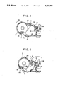
FIG. 6 is a longitudinal sectional view showing slide operation of the movable part due to engagement of a first linear slit of the movable part with an engagement projection of a stationary part;
FIG. 7 is a longitudinal sectional view showing slide operation of the movable part due to engagement of a second linear slit of the movable part with the engagement projection of the stationary part; and
FIG. 8 is a longitudinal sectional view showing the closed state of the recording paper cassette.
DESCRIPTION OF THE PREFERRED EMBODIMENTS
Referring now to FIGS. 3 to 8, an embodiment of the invention will be described. FIGS. 3 to 8 show, in longitudinal sectional form, a printer of the present embodiment with the depth thereof directed in a direction orthogonal to the sheet of drawing and for convenience of explanation, this direction is hereinafter referred to as a width direction of the printer.
As shown in FIG. 3, the printer according to the present embodiment has a recording paper cassette 1 for housing a rolled recording paper (web) 20, which cassette is formed integrally with a printer proper 10.
The recording paper cassette 1 includes a stationary part 2 and a movable part 3. The stationary part 2 has its one end side fixed to the printer proper 10 and the other end side having opposite ends in the width direction formed with engagement projections 2a.2a which engage guide slots 3a.3a formed in the movable part 3 as will be detailed later (in the figure, only one engagement projection 2a at one end in the width direction of the printer is depicted).
The movable part 3 is formed into a shape in which the rolled recording paper 20 can be loosely fitted and has its one end side having opposite ends in the width direction formed with the guide slots 3a.3a (in the figure, only one guide slot 3a at one end in the width direction of the printer is depicted). The guide slot 3a is bent midway to take a t-shape and includes a first linear slit 3b and a second linear slit 3c. With the engagement projections 2a.2a brought into engagement with the guide slots 3a.3a, the movable part 3 is so supported by the stationary part 2 as to be movable in the open/close direction of the recording paper cassette 1. The movable part 3 has its one end side supported by the stationary part 2 and the other openable free end side which supports a roller shaft 4 acting as a rotary shaft extending in the width direction. A platen roller 5 is jounalled on the roller shaft 4.
On the other hand, the printer proper 10 has a head frame 7 which supports a thermal recording head 6 extending in the width direction of the printer and the head frame 7 has at its opposite ends in the width direction lugs 7a.7a for receiving and supporting opposite ends in the width direction of the roller shaft 4 upon closure of the recording paper cassette 1 (in the figure, only one lug 7a at one end in the printer width direction illustrated). Lock release levers 8 are mounted to the opposite ends in the width direction of the head frame 7.
The lock release lever 8 is bent to take a t-shape and supported at its bent portion 8a on the head frame 7 so as to be rotatable in A1-A2 directions. The lock release lever 8 has one end passing through an insertion hole 10a formed in the printer proper 10 to form an operating handle 8b for lock release and the other end forming an engagement pawl 8c engageable with the roller shaft 4 provided to the movable part 3. The lock release lever 8 is normally urged to rotate in the Al direction by means of a spring member, not shown, and upon closure of the recording paper cassette 1, the engagement pawl 8c engages the roller shaft 4 to position and fix the mutually pressed state of the platen roller 5 and thermal recording head 6 but upon opening of the recording paper cassette 1, the operation handle 8b is operated by the user of the printer so as to be rotated in the A2 direction, thus releasing the engagement of the engagement pawl 8c with the roller shaft 4.
With the above construction, the process of setting the recording paper 20 in the printer is carried out as will be described below.
Firstly, as shown in FIG. 3, the movable part 3 of the recording paper cassette 1 is opened and subsequently, as shown in FIG. 4, a rolled recording paper 20 is loosely fitted in the movable part 3. At that time, the fore end of the recording paper 20 loosely fitted in the movable part 3 is paid out to overlie the top surface of the printer proper 10.
Thereafter, as shown in FIG. 5, the movable part 3 along with the recording paper 20 loosely fitted therein in the manner described previously is rotated in a direction of B about the engagement projection 2a of the stationary part 2. As the movable part 3 rotates, the platen roller 5 provided at the openable free end of the movable part 3 is moved into the printer proper 10 while entraining the recording paper 20, as shown in FIG. 6.
As the platen roller 5 moves into the printer proper 10 as described above, the engagement projection 2a in engagement with the first linear slit 3b of the guide slot 3a slides the movable part 3 in a direction of C, i.e., in the longitudinal direction of the first linear slit 3b, causing the roller shaft 4 to bear against the engagement pawl 8c of the lock release lever 8, as shown in FIG. 7.
Then, the engagement projection 2a engages the second linear slit 3c of the guide slot 3a to slide the movable part 3 in a direction of D, i.e., in the longitudinal direction of the second linear slit 3c. As a result, the roller shaft 4 is brought into engagement with the engagement pawl 8c of the lock release lever 8 and locked, as shown in FIG. 8, so that the recording paper is clamped by the platen roller 5 and thermal recording head 6, thus completing setting of the recording paper 20 in the printer. Printing onto the recording paper 20 thus clamped by the platen roller 5 and thermal recording head 6 in the aforementioned manner can be effected by conducting electrical current to the thermal recording head 6.
As described above, in the printer according to the present embodiment, the recording paper cassette 1 is formed integrally with the printer proper 10 and openably with respect thereto, the platen roller 5 is disposed at the openable free end of the movable part 3 constituting the recording paper cassette 1, and the thermal recording head 6 is disposed in the printer proper 10. Through this, setting of the recording paper 20 in the printer can automatically be effected concomitantly with moving operation of the movable part 3 during the closure of the recording paper cassette 1.
The roller shaft 4 also serving as the rotary shaft of the platen roller 5 cooperates with the lock release lever 8 provided to the head frame 7 for support of the thermal recording head 6 to constitute a lock mechanism. Therefore, a stable mutually pressed state of the platen roller 5 and thermal recording head 6 can be obtained.
As described above, in the printer of the invention, the recording paper cassette i formed integrally with the printer proper and openably with respect thereto, having its openable free end mounted with one of the thermal recording head and platen roller and the other end connected to the printer proper. Through this, setting of the recording paper in the printer proper can automatically be effected concomitantly with closing operation of the recording paper cassette and advantageously the user of the printer can be freed from the troublesome setting operation of the recording paper.
Particularly, when the platen roller on the one hand is disposed on openable free end of the recording paper cassette and the thermal recording head on the other hand is disposed in the printer proper, rigidity of mounting of the thermal recording head to the printer can be improved, giving rise to attainment of a stable mutually pressed state of the platen roller and thermal recording head to advantage.
Further, when the rotary shaft of the platen roller is brought into engagement with the lock release lever so as to be positioned and fixed with respect to the thermal recording head, the platen roller can be so controlled as to be pressed against the thermal recording head at a fixed position, giving rise to improved printing quality to advantage.
Furthermore, when the lock release lever is supported by the head frame for support of the thermal recording head, positioning of the platen roller and thermal recording head can be carried out directly, thereby further stabilizing the mutually pressed state of the platen roller and thermal recording head.

Claims (3)

What is claimed is:
1. A printer in which a rolled recording paper is housed in a recording paper cassette and printing onto the recording paper is carried out by conducting electrical current to a thermal recording head while the recording paper being clamped by the thermal recording head and a platen roller, wherein the recording paper cassette is formed integrally with a printer proper and openably with respect thereto, an openable free end of the recording paper cassette is mounted with the platen roller and the thermal recording head is disposed in said printer proper.
2. A printer in which a rolled recording paper is housed in a recording paper cassette and printing onto the recording paper is carried out by conducting electrical current to a thermal recording ahead while the recording paper being clamped by said thermal head and a platen roller, wherein said recording paper cassette is formed integrally with a printer proper and openably with respect thereto, an openable free end of said recording paper cassette is mounted with said platen roller, and said thermal recording head is disposed in said printer proper, wherein said platen roller has its rotary shaft brought into engagement with a lock release lever so as to be positioned and fixed with respect to said thermal recording head.
3. A printer in which a rolled recording paper is housed in a recording paper cassette and printing onto the recording paper is carried out by conducting electrical current to a thermal recording head while the recording paper being clamped by said thermal head and a platen roller, wherein said recording paper is formed integrally with a printer proper and openably with respect thereto, an openable free end of said recording paper cassette is mounted with said platen roller, and said thermal recording head is disposed in said printer proper, wherein said platen roller has its rotary shaft brought into engagement with a lock release lever so as to be positioned and fixed with respect to said thermal recording head, wherein said lock release lever is supported by a frame head for support of said thermal head.
US07/857,769 1991-03-27 1992-03-26 Printer with openable paper web cassette mounting a platen roller Expired - Lifetime US5201588A (en)

Applications Claiming Priority (2)

Application Number Priority Date Filing Date Title
JP3063473A JP3050622B2 (en) 1991-03-27 1991-03-27 Printing device
JP3-63473 1991-03-27

Publications (1)

Publication Number Publication Date
US5201588A true US5201588A (en) 1993-04-13

Family

ID=13230239

Family Applications (1)

Application Number Title Priority Date Filing Date
US07/857,769 Expired - Lifetime US5201588A (en) 1991-03-27 1992-03-26 Printer with openable paper web cassette mounting a platen roller

Country Status (4)

Country Link
US (1) US5201588A (en)
EP (1) EP0505943B1 (en)
JP (1) JP3050622B2 (en)
DE (1) DE69214181T2 (en)

Cited By (19)

* Cited by examiner, † Cited by third party
Publication number Priority date Publication date Assignee Title
US5411342A (en) * 1992-04-20 1995-05-02 Matsushita Electric Industrial Co., Ltd. Terminal device
US5486062A (en) * 1993-10-29 1996-01-23 Fujitsu Limited Printer-containing apparatus
US5576741A (en) * 1993-12-28 1996-11-19 General Scanning Inc. Configurable chart recorder
US5585828A (en) * 1993-08-03 1996-12-17 Societe D'applications Generales D'electricite Et De Mecanique Sagem Thermal printer
US5760814A (en) * 1995-07-13 1998-06-02 Samsung Electronics Co., Ltd. Device for uncurling thermal sensitive recording paper
US5791796A (en) * 1995-11-13 1998-08-11 Eltron International, Inc. Thermal printer with spring biased drive roller/platen
US5820279A (en) * 1995-09-22 1998-10-13 Eltron International, Inc. Computer driven printer
US5980140A (en) * 1996-03-13 1999-11-09 Esselte N.V. Tape printing apparatus and tape holding case having cooperative surface
US6155731A (en) * 1997-10-17 2000-12-05 Axiohm Transaction Solutions, Inc. Printing apparatus with cover actuated drive source
US6158342A (en) * 1999-09-27 2000-12-12 Axiohm Transaction Solutions, Inc. Paper supply adjustment mechanism
US6181361B1 (en) * 1998-07-22 2001-01-30 Dassault Automatismes Et Telecommunications Device for thermal printing of a rolled paper strip, in particular for a plug-in or cordless portable payment terminal
US6196741B1 (en) * 1997-05-28 2001-03-06 Matsushita Electric Industrial Co., Ltd. Printer
US6249301B1 (en) * 1999-09-27 2001-06-19 Shinko Electric Co., Ltd. Sublimation type color printer
US20020081136A1 (en) * 2000-12-21 2002-06-27 Samsung Electro-Mechanics Co.,Ltd Clamshell device for printers
US20030007823A1 (en) * 2001-07-09 2003-01-09 Nagano Fujitsu Component Limited Printing apparatus and terminal apparatus
US20030118390A1 (en) * 2001-11-16 2003-06-26 Rikuo Yamada Printer unit and printing apparatus incorporating the same
US20040070662A1 (en) * 2002-09-30 2004-04-15 Fujitsu Limited Handy thermal head printer
US20070269250A1 (en) * 2006-05-16 2007-11-22 First Data Corporation Printing Apparatus
US20090196671A1 (en) * 2008-01-29 2009-08-06 Alberto Campanini Printing roll release mechanism

Families Citing this family (10)

* Cited by examiner, † Cited by third party
Publication number Priority date Publication date Assignee Title
US5516219A (en) * 1994-08-01 1996-05-14 Lasermaster Corporation High resolution combination donor/direct thermal printer
CN1083775C (en) * 1996-11-08 2002-05-01 星精密株式会社 Recording apparatus
JPH10291707A (en) * 1997-04-15 1998-11-04 Brother Ind Ltd Web roll and web roll containing cassette
US6183153B1 (en) * 1998-04-30 2001-02-06 Sony Corporation Holder for roll-type print media, roll-type print media cassette, and printing apparatus
EP1543982A1 (en) * 2003-12-15 2005-06-22 Banksys S.A. Printer device
JP4492125B2 (en) * 2004-01-06 2010-06-30 ブラザー工業株式会社 Roll sheet holder and tape printer
EP2002985B1 (en) * 2007-05-18 2011-09-07 Schweers Informationstechnologie GmbH Mobile hand-held data processing device
JP5842159B2 (en) * 2011-09-06 2016-01-13 パナソニックIpマネジメント株式会社 Terminal device with printer
TWI451976B (en) * 2012-01-09 2014-09-11 Hiti Digital Inc Supporting mechanism and printer thereof
CN111532031B (en) * 2020-05-22 2021-09-21 南京六合高新建设发展有限公司 Thermal printer

Citations (19)

* Cited by examiner, † Cited by third party
Publication number Priority date Publication date Assignee Title
US3682407A (en) * 1970-03-03 1972-08-08 Harold Lichtenstein Tape cartridge for machines
JPS5775880A (en) * 1980-10-31 1982-05-12 Seiko Epson Corp Portable electronic calculator equipped with printer
JPS58148783A (en) * 1982-03-02 1983-09-03 Ricoh Co Ltd Recorder
US4445647A (en) * 1981-09-11 1984-05-01 International Standard Electric Corporation Supply roll holding arrangement
JPS59198169A (en) * 1983-04-26 1984-11-09 Canon Inc Image recorder
JPS60115471A (en) * 1983-11-26 1985-06-21 Matsushita Graphic Commun Syst Inc Recording paper containing device
JPS60168952A (en) * 1984-02-09 1985-09-02 Mitsubishi Electric Corp Stepless speed changer for car
JPS60187575A (en) * 1984-03-07 1985-09-25 Matsushita Graphic Commun Syst Inc Recorder
US4641980A (en) * 1984-10-02 1987-02-10 Fujitsu Limited Printer with pivotable print head attached to medium carrier moveable through a casing opening
US4663638A (en) * 1984-06-20 1987-05-05 Kabushiki Kaisha Toshiba Recording apparatus and method of transporting recording paper
JPS62159565A (en) * 1986-01-06 1987-07-15 Nec Corp Facsimile equipment
JPS6384960A (en) * 1986-09-30 1988-04-15 Anritsu Corp Thermal transfer color recorder
JPS63199669A (en) * 1987-02-16 1988-08-18 Silver Seiko Ltd Large-type printer
US4860031A (en) * 1983-09-22 1989-08-22 Goerz Electro Gesellschaft M.B.H. Register tape transport device
US4868676A (en) * 1986-03-19 1989-09-19 Shapr Kabushiki Kaisha Manual copying apparatus
US4910602A (en) * 1984-06-12 1990-03-20 Canon Kabushiki Kaisha Thermal recorder with ink sheet cassette removably mounted in openable housing
EP0372753A2 (en) * 1988-11-30 1990-06-13 Sony Corporation Printer paper-loading mechanism
US5060076A (en) * 1990-02-08 1991-10-22 Smith Corona Corporation Thermal paper cartridge for facsimile machine
US5092688A (en) * 1990-08-31 1992-03-03 Cognitive Solutions, Inc. Portable barcode printer

Family Cites Families (1)

* Cited by examiner, † Cited by third party
Publication number Priority date Publication date Assignee Title
JPH0315580A (en) * 1989-03-06 1991-01-23 Tokyo Electric Co Ltd Thermal printer

Patent Citations (19)

* Cited by examiner, † Cited by third party
Publication number Priority date Publication date Assignee Title
US3682407A (en) * 1970-03-03 1972-08-08 Harold Lichtenstein Tape cartridge for machines
JPS5775880A (en) * 1980-10-31 1982-05-12 Seiko Epson Corp Portable electronic calculator equipped with printer
US4445647A (en) * 1981-09-11 1984-05-01 International Standard Electric Corporation Supply roll holding arrangement
JPS58148783A (en) * 1982-03-02 1983-09-03 Ricoh Co Ltd Recorder
JPS59198169A (en) * 1983-04-26 1984-11-09 Canon Inc Image recorder
US4860031A (en) * 1983-09-22 1989-08-22 Goerz Electro Gesellschaft M.B.H. Register tape transport device
JPS60115471A (en) * 1983-11-26 1985-06-21 Matsushita Graphic Commun Syst Inc Recording paper containing device
JPS60168952A (en) * 1984-02-09 1985-09-02 Mitsubishi Electric Corp Stepless speed changer for car
JPS60187575A (en) * 1984-03-07 1985-09-25 Matsushita Graphic Commun Syst Inc Recorder
US4910602A (en) * 1984-06-12 1990-03-20 Canon Kabushiki Kaisha Thermal recorder with ink sheet cassette removably mounted in openable housing
US4663638A (en) * 1984-06-20 1987-05-05 Kabushiki Kaisha Toshiba Recording apparatus and method of transporting recording paper
US4641980A (en) * 1984-10-02 1987-02-10 Fujitsu Limited Printer with pivotable print head attached to medium carrier moveable through a casing opening
JPS62159565A (en) * 1986-01-06 1987-07-15 Nec Corp Facsimile equipment
US4868676A (en) * 1986-03-19 1989-09-19 Shapr Kabushiki Kaisha Manual copying apparatus
JPS6384960A (en) * 1986-09-30 1988-04-15 Anritsu Corp Thermal transfer color recorder
JPS63199669A (en) * 1987-02-16 1988-08-18 Silver Seiko Ltd Large-type printer
EP0372753A2 (en) * 1988-11-30 1990-06-13 Sony Corporation Printer paper-loading mechanism
US5060076A (en) * 1990-02-08 1991-10-22 Smith Corona Corporation Thermal paper cartridge for facsimile machine
US5092688A (en) * 1990-08-31 1992-03-03 Cognitive Solutions, Inc. Portable barcode printer

Cited By (27)

* Cited by examiner, † Cited by third party
Publication number Priority date Publication date Assignee Title
US5411342A (en) * 1992-04-20 1995-05-02 Matsushita Electric Industrial Co., Ltd. Terminal device
US5585828A (en) * 1993-08-03 1996-12-17 Societe D'applications Generales D'electricite Et De Mecanique Sagem Thermal printer
US5486062A (en) * 1993-10-29 1996-01-23 Fujitsu Limited Printer-containing apparatus
US5576741A (en) * 1993-12-28 1996-11-19 General Scanning Inc. Configurable chart recorder
US5760814A (en) * 1995-07-13 1998-06-02 Samsung Electronics Co., Ltd. Device for uncurling thermal sensitive recording paper
US5820279A (en) * 1995-09-22 1998-10-13 Eltron International, Inc. Computer driven printer
USRE36953E (en) * 1995-09-22 2000-11-14 Eltron International, Inc. Computer driven printer
US5791796A (en) * 1995-11-13 1998-08-11 Eltron International, Inc. Thermal printer with spring biased drive roller/platen
US5980140A (en) * 1996-03-13 1999-11-09 Esselte N.V. Tape printing apparatus and tape holding case having cooperative surface
US6196741B1 (en) * 1997-05-28 2001-03-06 Matsushita Electric Industrial Co., Ltd. Printer
US6270270B2 (en) 1997-05-28 2001-08-07 Matsushita Electric Industrial Co., Ltd. Printing apparatus
US6155731A (en) * 1997-10-17 2000-12-05 Axiohm Transaction Solutions, Inc. Printing apparatus with cover actuated drive source
US6181361B1 (en) * 1998-07-22 2001-01-30 Dassault Automatismes Et Telecommunications Device for thermal printing of a rolled paper strip, in particular for a plug-in or cordless portable payment terminal
US6249301B1 (en) * 1999-09-27 2001-06-19 Shinko Electric Co., Ltd. Sublimation type color printer
US6158342A (en) * 1999-09-27 2000-12-12 Axiohm Transaction Solutions, Inc. Paper supply adjustment mechanism
US20020081136A1 (en) * 2000-12-21 2002-06-27 Samsung Electro-Mechanics Co.,Ltd Clamshell device for printers
US6485210B2 (en) * 2000-12-21 2002-11-26 Samsung Electro-Mechanics Co., Ltd. Clamshell device for printers
US6814515B2 (en) * 2001-07-09 2004-11-09 Nagano Fujitsu Component Limited Printing apparatus and terminal apparatus
US20030007823A1 (en) * 2001-07-09 2003-01-09 Nagano Fujitsu Component Limited Printing apparatus and terminal apparatus
US20030118390A1 (en) * 2001-11-16 2003-06-26 Rikuo Yamada Printer unit and printing apparatus incorporating the same
US6758614B2 (en) * 2001-11-16 2004-07-06 Seiko Epson Corporation Printer unit and printing apparatus incorporating the same
US20040070662A1 (en) * 2002-09-30 2004-04-15 Fujitsu Limited Handy thermal head printer
US7116344B2 (en) * 2002-09-30 2006-10-03 Fujitsu Limited Handy thermal head printer
US20070269250A1 (en) * 2006-05-16 2007-11-22 First Data Corporation Printing Apparatus
US7806610B2 (en) * 2006-05-16 2010-10-05 First Data Corporation Printer with cover having laterally movable hinge
US20090196671A1 (en) * 2008-01-29 2009-08-06 Alberto Campanini Printing roll release mechanism
US8297863B2 (en) * 2008-01-29 2012-10-30 Custom Engineering S.P.A. Printing roll release mechanism

Also Published As

Publication number Publication date
DE69214181T2 (en) 1997-04-24
DE69214181D1 (en) 1996-11-07
JP3050622B2 (en) 2000-06-12
JPH04298356A (en) 1992-10-22
EP0505943A2 (en) 1992-09-30
EP0505943B1 (en) 1996-10-02
EP0505943A3 (en) 1992-12-16

Similar Documents

Publication Publication Date Title
US5201588A (en) Printer with openable paper web cassette mounting a platen roller
US6765602B2 (en) Thermal printer having a reduced size
JP3174062B2 (en) Printing equipment
JP3885136B2 (en) Tape cartridge holding mechanism and tape printer having the same
KR20030041100A (en) Printer unit and printing apparatus incorporating the same
JPH01160663A (en) Recording device
US4451167A (en) Printing device with swing-away cutter arrangement
JP3557832B2 (en) Thermal printer
US4107753A (en) Cassette holder capable of rotation through a larger angle of inclination
JP2720615B2 (en) Thermal printer
JPH05232789A (en) Lock mechanism of dolly for supporting developing apparatus
JPH04166373A (en) Facsimile
JP4918296B2 (en) Thermal printer
JPS6018367A (en) Recorder
JPS60172576A (en) Printer
JPS6019568A (en) Printer
JP3355703B2 (en) Thermal printer
JP2578625B2 (en) Cassette mounting device
JP3217797B2 (en) Printing press for printing strip media
KR900007458Y1 (en) Printer
JP3232424B2 (en) Recording device
JPH10194478A (en) Paper tray locking mechanism
JPS6313013Y2 (en)
JPS6339434B2 (en)
JP2614777B2 (en) Serial printer

Legal Events

Date Code Title Description
AS Assignment

Owner name: SHARP KABUSHIKI KAISHA A JAPANESE CORPORATION, JA

Free format text: ASSIGNMENT OF ASSIGNORS INTEREST.;ASSIGNORS:SAKAI, KATSUYUKI;SHIRAISHI, KENICHI;KIDA, SHIGERU;AND OTHERS;REEL/FRAME:006069/0604

Effective date: 19920113

STCF Information on status: patent grant

Free format text: PATENTED CASE

FEPP Fee payment procedure

Free format text: PAYOR NUMBER ASSIGNED (ORIGINAL EVENT CODE: ASPN); ENTITY STATUS OF PATENT OWNER: LARGE ENTITY

FPAY Fee payment

Year of fee payment: 4

FPAY Fee payment

Year of fee payment: 8

FPAY Fee payment

Year of fee payment: 12