US5204033A - Method of fabricating a preform in a resin transfer molding process - Google Patents
Method of fabricating a preform in a resin transfer molding process Download PDFInfo
- Publication number
- US5204033A US5204033A US07/780,008 US78000891A US5204033A US 5204033 A US5204033 A US 5204033A US 78000891 A US78000891 A US 78000891A US 5204033 A US5204033 A US 5204033A
- Authority
- US
- United States
- Prior art keywords
- preform
- fiber layer
- dry fiber
- mandrel
- transport means
- Prior art date
- Legal status (The legal status is an assumption and is not a legal conclusion. Google has not performed a legal analysis and makes no representation as to the accuracy of the status listed.)
- Expired - Fee Related
Links
Images


Classifications
-
- B—PERFORMING OPERATIONS; TRANSPORTING
- B29—WORKING OF PLASTICS; WORKING OF SUBSTANCES IN A PLASTIC STATE IN GENERAL
- B29B—PREPARATION OR PRETREATMENT OF THE MATERIAL TO BE SHAPED; MAKING GRANULES OR PREFORMS; RECOVERY OF PLASTICS OR OTHER CONSTITUENTS OF WASTE MATERIAL CONTAINING PLASTICS
- B29B11/00—Making preforms
- B29B11/14—Making preforms characterised by structure or composition
- B29B11/16—Making preforms characterised by structure or composition comprising fillers or reinforcement
-
- B—PERFORMING OPERATIONS; TRANSPORTING
- B29—WORKING OF PLASTICS; WORKING OF SUBSTANCES IN A PLASTIC STATE IN GENERAL
- B29C—SHAPING OR JOINING OF PLASTICS; SHAPING OF MATERIAL IN A PLASTIC STATE, NOT OTHERWISE PROVIDED FOR; AFTER-TREATMENT OF THE SHAPED PRODUCTS, e.g. REPAIRING
- B29C31/00—Handling, e.g. feeding of the material to be shaped, storage of plastics material before moulding; Automation, i.e. automated handling lines in plastics processing plants, e.g. using manipulators or robots
- B29C31/04—Feeding of the material to be moulded, e.g. into a mould cavity
- B29C31/08—Feeding of the material to be moulded, e.g. into a mould cavity of preforms to be moulded, e.g. tablets, fibre reinforced preforms, extruded ribbons, tubes or profiles; Manipulating means specially adapted for feeding preforms, e.g. supports conveyors
-
- B—PERFORMING OPERATIONS; TRANSPORTING
- B29—WORKING OF PLASTICS; WORKING OF SUBSTANCES IN A PLASTIC STATE IN GENERAL
- B29C—SHAPING OR JOINING OF PLASTICS; SHAPING OF MATERIAL IN A PLASTIC STATE, NOT OTHERWISE PROVIDED FOR; AFTER-TREATMENT OF THE SHAPED PRODUCTS, e.g. REPAIRING
- B29C69/00—Combinations of shaping techniques not provided for in a single one of main groups B29C39/00 - B29C67/00, e.g. associations of moulding and joining techniques; Apparatus therefore
- B29C69/001—Combinations of shaping techniques not provided for in a single one of main groups B29C39/00 - B29C67/00, e.g. associations of moulding and joining techniques; Apparatus therefore a shaping technique combined with cutting, e.g. in parts or slices combined with rearranging and joining the cut parts
- B29C69/002—Winding
-
- B—PERFORMING OPERATIONS; TRANSPORTING
- B29—WORKING OF PLASTICS; WORKING OF SUBSTANCES IN A PLASTIC STATE IN GENERAL
- B29C—SHAPING OR JOINING OF PLASTICS; SHAPING OF MATERIAL IN A PLASTIC STATE, NOT OTHERWISE PROVIDED FOR; AFTER-TREATMENT OF THE SHAPED PRODUCTS, e.g. REPAIRING
- B29C70/00—Shaping composites, i.e. plastics material comprising reinforcements, fillers or preformed parts, e.g. inserts
- B29C70/04—Shaping composites, i.e. plastics material comprising reinforcements, fillers or preformed parts, e.g. inserts comprising reinforcements only, e.g. self-reinforcing plastics
- B29C70/28—Shaping operations therefor
- B29C70/54—Component parts, details or accessories; Auxiliary operations, e.g. feeding or storage of prepregs or SMC after impregnation or during ageing
- B29C70/543—Fixing the position or configuration of fibrous reinforcements before or during moulding
-
- B—PERFORMING OPERATIONS; TRANSPORTING
- B29—WORKING OF PLASTICS; WORKING OF SUBSTANCES IN A PLASTIC STATE IN GENERAL
- B29C—SHAPING OR JOINING OF PLASTICS; SHAPING OF MATERIAL IN A PLASTIC STATE, NOT OTHERWISE PROVIDED FOR; AFTER-TREATMENT OF THE SHAPED PRODUCTS, e.g. REPAIRING
- B29C2793/00—Shaping techniques involving a cutting or machining operation
- B29C2793/0081—Shaping techniques involving a cutting or machining operation before shaping
-
- B—PERFORMING OPERATIONS; TRANSPORTING
- B29—WORKING OF PLASTICS; WORKING OF SUBSTANCES IN A PLASTIC STATE IN GENERAL
- B29K—INDEXING SCHEME ASSOCIATED WITH SUBCLASSES B29B, B29C OR B29D, RELATING TO MOULDING MATERIALS OR TO MATERIALS FOR MOULDS, REINFORCEMENTS, FILLERS OR PREFORMED PARTS, e.g. INSERTS
- B29K2105/00—Condition, form or state of moulded material or of the material to be shaped
- B29K2105/06—Condition, form or state of moulded material or of the material to be shaped containing reinforcements, fillers or inserts
- B29K2105/08—Condition, form or state of moulded material or of the material to be shaped containing reinforcements, fillers or inserts of continuous length, e.g. cords, rovings, mats, fabrics, strands or yarns
- B29K2105/10—Cords, strands or rovings, e.g. oriented cords, strands or rovings
- B29K2105/101—Oriented
Definitions
- This invention generally is directed to resin transfer molding and, particularly, to the fabrication of a resin transfer molding preform including filament winding the preform and transporting the preform intact to a resin transfer mold cavity.
- Resin transfer molding has been used to manufacture composite or filament oriented structures of various sizes and shapes.
- this approach which emerged from the textile industry, involves the assembly of dry, unimpregnated fibrous preforms for subsequent injection or infusion of a matrix resin, such as epoxy or the like.
- a matrix resin such as epoxy or the like.
- fabric is the starting point for most preforms because the fabric positions the reinforcing fibers in principal directions.
- Preform fabrics can be of any one of the conventional fabrics, such as a plain weave, satin, unidirectional or multidirectional knitted or bias weave fabrics. The fabric selection usually is dependent upon the final properties desired in the structure as well as the configuration of the manufactured part.
- non-crimped fabric that is, knitted and woven unidirectional fabrics
- increase in tensile and compression performance is gained by eliminating the kinks within fiber bundles that result from the over-and-under construction of woven materials.
- Preform fabrics may be of fiberglass, carbon and aramid fibers. Silicone carbide, aluminum oxide, boron, borsic, quartz and other fibers also are used in specific applications. As with all composite structures, selecting the reinforcing fiber for the preform depends on the end-use characteristics desired in the composite structure.
- resin transfer molding is a closed mold, low pressure process applicable to the fabrication of complex, high performance composite articles of both large and small size.
- resin transfer molding processes are known in the art, as set forth in somewhat detail in that patent. The process is differentiated from various other molding processes in that reinforcement fibrous material is placed separately into a molding tool cavity and then combined with resin within the mold cavity to form a fiber reinforced plastic composite product.
- reinforcement fibrous material is placed separately into a molding tool cavity and then combined with resin within the mold cavity to form a fiber reinforced plastic composite product.
- a pre-shaped fiber reinforcement is positioned within a molding tool cavity and the molding tool then is closed.
- a feed line connects the closed molding cavity with a supply of liquid resin and the resin is pumped into the cavity where it impregnates and envelopes the fiber reinforcement and subsequently cures or is cured.
- Preform assembly converts individual fabrics into a multilayered configuration specified by the composite designer.
- the fabric layers are assembled into the final configuration in a process analogous to a prepreg lamination operation.
- Fabric layers are placed in a predetermined orientation by rotating the principal axes of the fabric layers or by using a multidirectional fabric.
- the assembly process can be automated by using broad goods spreaders and robotic placement.
- the final operation in preform assembly is the stitching process. Stitching mechanically fixes the final shape of the preform and constrains fiber movement during resin impregnation.
- Resin injection fusion is a technique for impregnating preforms with hot-melt resin systems, which are resins that are solid at room temperature. These resins include typical aerospace-grade epoxies, bismaleimides, and polyimides.
- Preforms are loaded into a holding fixture to stabilize the preform during the infusion process. Resin, in film form, is positioned uniformly onto the preform. Actual impregnation occurs in a heated vacuum chamber. The preform, with resin applied, is positioned in the chamber. Heat is then transmitted to the preform and resin by means of infrared radiation. A vacuum is applied during the impregnation cycle to remove entrained air and volatiles from the filmed resin. Preform impregnation occurs through capillary wetting of the preform as the viscosity of the resin decreases. During impregnation, the vacuum is cycled to prevent excessive resin bubbling and provide a mechanical pumping action to complement capillary wetting. At the end of this cycle, the resin is not cured.
- the final sequence is the molding operation itself, which establishes the final shape of the composite structure, fixes the proportions of fiber and resin, cures the resin, and provides the composite structure with its designated mechanical and thermal properties.
- thermosetting resin is injected into a cavity having the shape of the desired part.
- the cavity is filled with a dry fiber preform.
- the preform can include closed-cell cores and metal inserts, in addition to the fabric/mat materials.
- the process is typically used with low-viscosity fast-curing resins, such as polyester and epoxy, and chopped-strand or continuous mat reinforcement at a low fiber volume.
- low-viscosity fast-curing resins such as polyester and epoxy
- chopped-strand or continuous mat reinforcement at a low fiber volume.
- the process has been demonstrated with higher fiber volumes of oriented material and higher-performance matrices, such as polyimides.
- This invention is directed to solving the above problems and satisfying the need for a new and improved filament wound resin transfer molding preform assembly process.
- An object, therefore, of the invention is to provide a new and improved method of fabricating a preform for use in a resin transfer molding process, the method being extremely cost-effective and simple in performance.
- the method generally includes the steps of locating a transport means on a mandrel, and filament winding a dry fiber layer or thickness about the mandrel over the transport means.
- a tackifier is applied to the dry fiber layer at least in the area of the transport means.
- the filament wound dry fiber layer is cut about the transport means to provide a preform thereon.
- the preform is transported to a resin transfer mold by means of the transfer means, and the preform is fabricated by a resin transfer molding process in the mold.
- the invention contemplates a novel transport means and cover structure which not only facilitates transporting the preform to the mold cavity, but facilitates cutting the preform from the mandrel in a desired shape. More particularly, an inner shell is laid-up and cured on the mandrel before filament winding the thickness which forms the preform.
- the inner shell includes a plurality of sections, with the transport means being one of the sections. The periphery of the one section defines a cut line for cutting the preform from the filament wound dry fiber layer which is wound over the inner shell.
- An outer shell of composite material also is laid-up and cured over the cured inner shell before filament winding the dry fiber layer which forms the preform.
- the outer shell also includes a plurality of sections including a cover section of the same shape and in registry with the one section of the inner shell which defines the transport means.
- the cured outer shell is provided for positioning over the filament wound dry fiber layer to sandwich the preform between the shells.
- a filler layer such as rubber or the like, is positioned over the cured inner shell before laying-up the outer shell.
- the filler layer is of the same thickness as the filament wound dry fiber layer which forms the preform.
- tackifier by feeding the filaments to be wound about the mandrel through a tackifier bath. Additional tackifier is sprayed onto the wound filaments.
- the filaments preferably are wound in different winding patterns, such as helical and circumferential patterns.
- a cutting barrier such as a thin sheet of metal material (e.g., brass or the like) is positioned on the mandrel about the area of the transport means to prevent scoring of the mandrel by a cutting instrument.
- the filament wound dry fiber layer before it is cut to form the preform. This can be performed by a heat-shrink tape, clam-shell structures or the like.
- the cut preform is transported from the mandrel to the resin transfer molding cavity by the preform being sandwiched between the inner and outer shells which were used sort of as a template to cut the preform, the sandwiching shells maintaining the filament configuration of the preform during cutting.
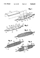
- FIG. 1 is a perspective view of a mandrel having the inner shell positioned thereon, and the one section of the shell which forms the shape of the preform being removed to facilitate the illustration;
- FIG. 2 is a view similar to that of FIG. 1 with the removed section of FIG. 1 back in position on the mandrel;
- FIG. 3 illustrates a step of the method wherein the helical windings of the filament wound dry fiber layer are wound over the inner shell;
- FIG. 4 is a view similar to that of FIG. 3, illustrating the circumferential windings over the helical windings;
- FIG. 5 shows a shrink tape being applied over the area of the filament wound dry fiber layer which includes the preform area
- FIG. 6 shows the outer shell applied over the filament wound dry fiber layer with a pair of clamps holding a cover section of the outer shell to facilitate cutting about the periphery of the preform
- FIG. 7 is a view similar to that of FIG. 6, with the clamps moved to finish the cutting operation;
- FIG. 8 is a perspective view of the cut preform and cover section of the outer shell removed from the mandrel
- FIG. 9 is an exploded schematic illustration of a mold tool for resin transfer molding the preform, the tool being in open condition;
- FIG. 10 is a view similar to that of FIG. 9, with the mold tool in closed condition;
- FIG. 11 is a somewhat schematic illustration of a winding mandrel showing an alternate form of transport means.
- FIG. 12 is a fragmented section taken generally along line 12--12 of FIG. 11.
- the invention is directed to a method of fabricating a preform for use in a resin transfer molding process, and particularly wherein the preform is fabricated of a dry fiber layer or thickness of filament wound material.
- a reusable mandrel 16 is provided of steel material or the like.
- the mandrel is conventional and has end shaft fittings 18 for rotating the mandrel in a filament winding apparatus.
- the invention contemplates fabricating a preform in a number of layers of "dry" fiber reinforcement which are filament wound on mandrel 16, cut from the mandrel and placed in a mold where resin is injected, i.e. in a resin transfer molding process.
- the method of the invention allows the dry fibers to be wound on the mandrel and then accurately cut from the mandrel without disturbing the desired fiber orientation. This is accomplished by the use of special tools in the form of inner and outer shells.
- the "tools" of the invention actually comprise composites which are cured on mandrel 16, before the filament winding steps, and then used as the tooling for fabricating the preform and transferring the preform to the resin molding cavity.
- FIGS. 1 and 2 show an inner shell, generally designated 20, which is fabricated in a plurality of sections, namely four corner or quadrant sections 22 and a center section 24. All of sections 22, 24 are fabricated from a plurality (e.g. ten) plies of fibrous cloth impregnated with an epoxy resin. The cloth may be of glass fabric and the plies are stacked and cured on the reusable steel mandrel in a desired shape.
- each of sections 22 include a plurality of plies of cloth cut into a rectangular shape, with the inner adjacent corners of the sections cut-out to form a rectangular cavity 26 (FIG. 2) within which center section 24 can be positioned as shown in FIG. 3.
- the center section is laid-up of the same numbers of plies of cloth as corner sections 22. Pins 28 can be seen projecting from mandrel 16 through corner sections 22 for properly locating the corner sections.
- a cutting barrier 30 can be positioned on the mandrel about the area of center section 24 to protect the mandrel from scoring (as described hereinafter) since, preferably, the mandrel is reusable.
- the cutting barrier may be provided in the form of a 0.01 inch thick sheet of brass shim stock adhered to the mandrel by tape, appropriate adhesive or the like.
- FIG. 3 shows a helical layer of filaments which have been wound over the layer at a winding angle of approximately 18 degrees with respect to the mandrel's longitudinal axis.
- a "dry"fiber consisting of Owens Corning S-2 glass fiber was used, and one helical layer (two plies) was applied to the mandrel. The total tension of the glass fibers was on the order of fourteen pounds. This corresponds to individual strand tension of approximately 3.5 pounds.
- one layer of circumferential windings has been applied over the glass helical layer.
- the circumferential windings were applied at an angle of approximately 90 degrees with respect to the longitudinal axis of the mandrel.
- the circumferential windings specifically were of Amoco T650/35 12K graphite roving. Strand tension measured approximately 3.5 pounds.
- a tackifier is applied to the wound filaments.
- the dry fiber may be fed through a bath of acetone solvent which contains a powdered tackifier, such as Dow Corporation Tactix 226 tackifier at a mixture of 5% tackifier by weight.
- a powdered tackifier such as Dow Corporation Tactix 226 tackifier at a mixture of 5% tackifier by weight.
- This tackifier helps to bond the wound dry fibers together to improve handling.
- Additional tackifier solution may be sprayed directly onto the wound fiber.
- the tackifier provides a temporary binder to facilitate maintaining fiber orientation when transporting the preform to the resin transfer molding cavity.
- a compaction step may be used to again maintain the fiber orientation.
- One process for compaction of the wound fibers is by means of a heat-shrink tape 36 (FIG. 5) which is wrapped about the area of the preform (i.e. center section 24 of inner shell 20), and the tape is shrunk by applying heat thereto by any appropriate means, as at 38.
- a heat-shrink tape 36 FIG. 5
- other types of compaction means can be used such as clamps, clam shells and the like.
- outer shell 40 is placed over the filament wound dry fiber layer.
- outer shell 40 will have been fabricated preliminarily similar to the fabrication of inner shell 20.
- the outer shell again is fabricated of a plurality of sections, including corner or quadrant sections 42 and a center section 44. These sections are dimensioned similar to sections 22 and 24 of inner shell 20.
- the sections are fabricated by laying-up a plurality of plies of impregnated fibrous cloth and curing the sections in position on mandrel 16 over the inner shell so that the shells match in contour.
- a filler layer (not shown) is disposed between the inner shell and the outer shell before curing the outer shell.
- a layer of flexible material such as rubber, is sandwiched between the inner and outer shells and of the same expected thickness of the filament wound dry fiber layer (e.g. 0.060 inch thick).
- the filler layer and the outer shell are removed and put aside for winding the dry fiber layer as shown and described above in relation to FIGS. 3-5.
- the shells and their various sections are reusable in a production environment.
- FIG. 6 a form of means might be used to hold sections 42 and 44 of outer shell 40 down against the filament wound dry fiber layer.
- circular clamps 46 FIG. 6
- the cutting tool then was used to cut along the side or longitudinal edges of the center section and through the filament wound dry fiber layer.
- the clamps then were moved inwardly as shown in FIG. 7 to cut the end edges and the corners about the center section to complete the cut to form a corresponding rectangular section through the filament wound dry fiber layer.
- outer shell 40 has proven advantageous to maintain the shape of the filament wound dry fiber layer 32, 34 and to maintain the orientation of the filaments of the composite.
- other cutting means can be used rather than a physical or mechanical cutting tool having a straight cutting edge.
- the dry fiber layer can be laser cut. In such an instance, the outer shell might be totally eliminated.
- FIG. 8 shows the entire sandwich removed from the mandrel, with cutting barrier 30 visible through the cut-out area in FIG. 8.
- the bottom portion of FIG. 8 shows the cut center section 44 of the outer shell flipped over to expose the cut-out preform "P", the preform resting on top of center section 24 of the inner shell.
- FIGS. 9 and 10 somewhat schematically illustrate a mold including a lower mold half 60 and an upper mold half 62, the lower mold half having a molding cavity 64.
- Center section 24 of the inner shell is shown supporting preform "P" including inner helical windings 32 and outer circumferential windings 34. This subassembly is positioned into cavity 64 as shown in FIG. 10.
- Upper mold half 62 then is closed onto lower mold half 60.
- Resin then is injected into the cavity through an appropriate passage 66 to infuse or impregnate the filament wound preform for curing into the desired shape as defined by the transport means of center section 24 of the inner shell, the shape being shown straight in FIGS. 9 and 10 as if taken in the longitudinal direction of the preform as indicated by line 9--9 in FIG. 8.
- FIGS. 11 and 12 show an embodiment of the invention wherein bottom shell 20 (FIG. 2) has been eliminated at least to the extent of fabricating the inner shell or tooling in a plurality of sections.
- a reusable mandrel 68 is provided with a contoured cavity 70 of a depth for receiving a transport member 72.
- the transport member 72 would correspond to center section 24 of inner shell 20.
- Mandrel 68 may be fabricated of the vacuum type which would include vacuum passages 74 within cavity 70 to hold transport member 72 down onto the mandrel. This vacuum hold-down concept also is contemplated in relation to the sectioned inner shell 20, described above. Of course, passages 74 would be appropriately connected to a source of vacuum.
- the filament wound dry fiber layer such as windings 32 and 34 (FIGS. 3 and 4, respectively) would be wound directly onto mandrel 68 over the top of transport member 72. Once wound, the preform would be cut about the periphery of the transport member in any of the processes described above.
- the transport member would be used similarly to center section 24 of inner shell 20 to transport the preform to an appropriate resin transfer molding cavity.
Abstract
Description
Claims (37)
Priority Applications (1)
| Application Number | Priority Date | Filing Date | Title |
|---|---|---|---|
| US07/780,008 US5204033A (en) | 1991-10-21 | 1991-10-21 | Method of fabricating a preform in a resin transfer molding process |
Applications Claiming Priority (1)
| Application Number | Priority Date | Filing Date | Title |
|---|---|---|---|
| US07/780,008 US5204033A (en) | 1991-10-21 | 1991-10-21 | Method of fabricating a preform in a resin transfer molding process |
Publications (1)
| Publication Number | Publication Date |
|---|---|
| US5204033A true US5204033A (en) | 1993-04-20 |
Family
ID=25118277
Family Applications (1)
| Application Number | Title | Priority Date | Filing Date |
|---|---|---|---|
| US07/780,008 Expired - Fee Related US5204033A (en) | 1991-10-21 | 1991-10-21 | Method of fabricating a preform in a resin transfer molding process |
Country Status (1)
| Country | Link |
|---|---|
| US (1) | US5204033A (en) |
Cited By (39)
| Publication number | Priority date | Publication date | Assignee | Title |
|---|---|---|---|---|
| US5348698A (en) * | 1992-03-17 | 1994-09-20 | Agency Of Defense Development | Method for manufacturing pressure container having opposite dome ends with different opening diameters |
| US5427726A (en) * | 1993-06-15 | 1995-06-27 | The Dow Chemical Company | Process for resin transfer molding using a partially cured tackifier |
| US5427725A (en) * | 1993-05-07 | 1995-06-27 | The Dow Chemical Company | Process for resin transfer molding and preform used in the process |
| US5433165A (en) * | 1994-03-30 | 1995-07-18 | Outboard Marine Corporation | Method of manufacturing a boat hull |
| US5476627A (en) * | 1994-06-24 | 1995-12-19 | Bell Helicopter Textron Inc. | Composite molding process utilizing tackified fabric material |
| US5492663A (en) * | 1994-06-20 | 1996-02-20 | General Motors Corporation | Coordinated texture harmony between formed material and molded components |
| US5496602A (en) * | 1994-11-22 | 1996-03-05 | Dow-United Technologies Composite Products, Inc. | Low resin content unidirectional fiber tape |
| WO1996022871A1 (en) * | 1995-01-27 | 1996-08-01 | Mcdonnell Douglas Helicopter Company | Method of resin transfer molding |
| US5547533A (en) * | 1991-05-24 | 1996-08-20 | Composite Scandinavia Ab | Method for manufacturing glass-fibre reinforced plastic container |
| US5588392A (en) * | 1995-04-18 | 1996-12-31 | Outboard Marine Corporation | Resin transfer molding process |
| US5698318A (en) * | 1995-05-23 | 1997-12-16 | The Dow Chemical Company | Process for resin transfer molding and formulations useful to practice it |
| US5766534A (en) * | 1994-10-28 | 1998-06-16 | The Dow Chemical Company | Process for preparing a resin matrix composite using a preform |
| US5806387A (en) * | 1995-04-10 | 1998-09-15 | N.V. Owens-Corning S.A. | Method for dispensing resinated reinforcement fibers |
| US5819614A (en) * | 1995-04-10 | 1998-10-13 | N.V. Owens-Corning S.A. | Method for dispensing reinforcement fibers |
| US5993713A (en) * | 1992-12-01 | 1999-11-30 | De La Puerta; Enrique | Reinforced composite shapes and method and apparatus for their manufacture |
| US6029897A (en) * | 1998-03-19 | 2000-02-29 | N.V. Owens-Corning S.A. | Method of dispensing chopped reinforcement strand using a vortex nozzle |
| US6038949A (en) * | 1998-09-14 | 2000-03-21 | Nv Owens-Corning S.A. | Method for dispensing reinforcement fibers |
| US6231941B1 (en) * | 1998-07-14 | 2001-05-15 | The Boeing Company | Radius fillers for a resin transfer molding process |
| US6524515B1 (en) * | 1998-09-03 | 2003-02-25 | Cavalli S.R.L. | Method of producing a vehicle steering wheel |
| US20040033347A1 (en) * | 2001-03-05 | 2004-02-19 | Lauersdorf William F. | Method of making a composite with a barrier layer in a closed mold process and composite produced thereby |
| US20040250875A1 (en) * | 2003-05-29 | 2004-12-16 | Invision Investments, Inc. | Purging system for a liquid dispensing nozzle |
| US6893712B2 (en) * | 1999-06-09 | 2005-05-17 | Nippon Mitsubishi Oil Corp. | Transport member |
| WO2005049304A1 (en) * | 2003-11-18 | 2005-06-02 | The Boeing Company | Method of transferring large uncured composite laminates |
| US6994051B2 (en) | 1999-09-24 | 2006-02-07 | Vec Industries, L.L.C. | Boat and method for manufacturing using resin transfer molding |
| US20080047657A1 (en) * | 2006-08-25 | 2008-02-28 | Jander Michael H | System for forming reinforcement layers having cross-directionally oriented fibers |
| US20080185754A1 (en) * | 2007-01-19 | 2008-08-07 | John Wirt | Method and apparatus for molding composite articles |
| WO2008128715A1 (en) * | 2007-04-18 | 2008-10-30 | Dsm Ip Assets B.V. | Method of producing a curved product comprising drawn polymer reinforcing elements and product obtained thereby |
| EP2151312A1 (en) * | 2008-08-07 | 2010-02-10 | Delft University of Technology | Semi-finished product and method for obtaining it |
| US20100135817A1 (en) * | 2008-10-22 | 2010-06-03 | Wirt John C | Wind turbine blade and method for manufacturing thereof |
| WO2012042261A1 (en) * | 2010-10-01 | 2012-04-05 | Vestas Wind Systems A/S | Method for manufacturing wind turbine blades |
| US20120138216A1 (en) * | 2010-12-07 | 2012-06-07 | Jkm Technologies, Llc | Filament Wound U-Shaped Support Units for Footwear |
| DE102013201728A1 (en) * | 2013-02-04 | 2014-08-07 | Bayerische Motoren Werke Aktiengesellschaft | Core and process for producing fiber-reinforced plastic semi-finished products |
| US20150004357A1 (en) * | 2011-04-12 | 2015-01-01 | Airbus Operations Gmbh | Method and a device for the manufacture of a fibre composite component, and a fibre composite component |
| CN105128225A (en) * | 2015-10-12 | 2015-12-09 | 核工业理化工程研究院 | Mounting and dismounting transferring device used for cylindrical winding core mold |
| US9944063B1 (en) * | 2016-05-23 | 2018-04-17 | Boral Ip Holdings (Australia) Pty Limited | Method of producing reinforced substrate |
| DE102018115325A1 (en) * | 2018-06-26 | 2020-01-02 | Schmidt & Heinzmann Gmbh & Co. Kg | Preforming tool at least for producing a preform of a composite component |
| WO2020111215A1 (en) | 2018-11-30 | 2020-06-04 | 東レ株式会社 | Sheet-shaped reinforced-fiber base material and manufacturing method therefor |
| US10821681B2 (en) | 2017-01-20 | 2020-11-03 | General Electric Company | Liquid infusion molded ceramic matrix composites and methods of forming the same |
| US20200398520A1 (en) * | 2018-03-05 | 2020-12-24 | Nippi Corporation | Method for forming honeycomb sandwich composite material and jig used therefor |
Citations (9)
| Publication number | Priority date | Publication date | Assignee | Title |
|---|---|---|---|---|
| US3700535A (en) * | 1971-03-12 | 1972-10-24 | Atomic Energy Commission | Carbon fiber structure and method of forming same |
| US3873291A (en) * | 1974-03-29 | 1975-03-25 | Nicofibers Inc | Method of producing glass fiber mats |
| US4121002A (en) * | 1977-07-06 | 1978-10-17 | The United States Of America As Represented By The Secretary Of The Air Force | Fabrication of antenna windows |
| US4167429A (en) * | 1977-11-30 | 1979-09-11 | Ppg Industries, Inc. | Method of manufacturing resin sheets reinforced with glass and carbon strand |
| US4385952A (en) * | 1980-08-27 | 1983-05-31 | Mitsubishi Denki Kabushiki Kaisha | Process for preparing fiber reinforced plastics |
| US4512836A (en) * | 1983-08-22 | 1985-04-23 | Mcdonnell Douglas Corporation | Method of producing composite structural members |
| US4740262A (en) * | 1986-01-24 | 1988-04-26 | Ecodyne Corporation | Method of manufacturing a pressure vessel with an improved sidewall structure |
| US4762740A (en) * | 1987-06-15 | 1988-08-09 | Ford Motor Company | Resin transfer molding core, preform and process |
| US5037599A (en) * | 1989-06-26 | 1991-08-06 | Basf Aktiengesellschaft | Single diaphragm forming of drapeable thermoplastic impregnated composite materials |
-
1991
- 1991-10-21 US US07/780,008 patent/US5204033A/en not_active Expired - Fee Related
Patent Citations (9)
| Publication number | Priority date | Publication date | Assignee | Title |
|---|---|---|---|---|
| US3700535A (en) * | 1971-03-12 | 1972-10-24 | Atomic Energy Commission | Carbon fiber structure and method of forming same |
| US3873291A (en) * | 1974-03-29 | 1975-03-25 | Nicofibers Inc | Method of producing glass fiber mats |
| US4121002A (en) * | 1977-07-06 | 1978-10-17 | The United States Of America As Represented By The Secretary Of The Air Force | Fabrication of antenna windows |
| US4167429A (en) * | 1977-11-30 | 1979-09-11 | Ppg Industries, Inc. | Method of manufacturing resin sheets reinforced with glass and carbon strand |
| US4385952A (en) * | 1980-08-27 | 1983-05-31 | Mitsubishi Denki Kabushiki Kaisha | Process for preparing fiber reinforced plastics |
| US4512836A (en) * | 1983-08-22 | 1985-04-23 | Mcdonnell Douglas Corporation | Method of producing composite structural members |
| US4740262A (en) * | 1986-01-24 | 1988-04-26 | Ecodyne Corporation | Method of manufacturing a pressure vessel with an improved sidewall structure |
| US4762740A (en) * | 1987-06-15 | 1988-08-09 | Ford Motor Company | Resin transfer molding core, preform and process |
| US5037599A (en) * | 1989-06-26 | 1991-08-06 | Basf Aktiengesellschaft | Single diaphragm forming of drapeable thermoplastic impregnated composite materials |
Cited By (76)
| Publication number | Priority date | Publication date | Assignee | Title |
|---|---|---|---|---|
| US5547533A (en) * | 1991-05-24 | 1996-08-20 | Composite Scandinavia Ab | Method for manufacturing glass-fibre reinforced plastic container |
| US5698065A (en) * | 1991-05-24 | 1997-12-16 | Composite Scandinavia Ab | Apparatus for manufacturing glass-fibre-reinforced plastic container |
| US5348698A (en) * | 1992-03-17 | 1994-09-20 | Agency Of Defense Development | Method for manufacturing pressure container having opposite dome ends with different opening diameters |
| US5993713A (en) * | 1992-12-01 | 1999-11-30 | De La Puerta; Enrique | Reinforced composite shapes and method and apparatus for their manufacture |
| US5427725A (en) * | 1993-05-07 | 1995-06-27 | The Dow Chemical Company | Process for resin transfer molding and preform used in the process |
| US5427726A (en) * | 1993-06-15 | 1995-06-27 | The Dow Chemical Company | Process for resin transfer molding using a partially cured tackifier |
| US5526767A (en) * | 1994-03-30 | 1996-06-18 | Outboard Marine Coporation | Method of manufacturing a boat hull |
| US5433165A (en) * | 1994-03-30 | 1995-07-18 | Outboard Marine Corporation | Method of manufacturing a boat hull |
| US5492663A (en) * | 1994-06-20 | 1996-02-20 | General Motors Corporation | Coordinated texture harmony between formed material and molded components |
| US5716686A (en) * | 1994-06-24 | 1998-02-10 | Bell Helicopter Textron Inc. | Tackified fabric material and process for manufacture |
| WO1996000145A1 (en) * | 1994-06-24 | 1996-01-04 | Bell Helicopter Textron Inc. | Tackified fabric material and process for manufacture |
| US5476627A (en) * | 1994-06-24 | 1995-12-19 | Bell Helicopter Textron Inc. | Composite molding process utilizing tackified fabric material |
| US5766534A (en) * | 1994-10-28 | 1998-06-16 | The Dow Chemical Company | Process for preparing a resin matrix composite using a preform |
| US5496602A (en) * | 1994-11-22 | 1996-03-05 | Dow-United Technologies Composite Products, Inc. | Low resin content unidirectional fiber tape |
| WO1996022871A1 (en) * | 1995-01-27 | 1996-08-01 | Mcdonnell Douglas Helicopter Company | Method of resin transfer molding |
| US5806387A (en) * | 1995-04-10 | 1998-09-15 | N.V. Owens-Corning S.A. | Method for dispensing resinated reinforcement fibers |
| US5819614A (en) * | 1995-04-10 | 1998-10-13 | N.V. Owens-Corning S.A. | Method for dispensing reinforcement fibers |
| US5588392A (en) * | 1995-04-18 | 1996-12-31 | Outboard Marine Corporation | Resin transfer molding process |
| US5698318A (en) * | 1995-05-23 | 1997-12-16 | The Dow Chemical Company | Process for resin transfer molding and formulations useful to practice it |
| US6029897A (en) * | 1998-03-19 | 2000-02-29 | N.V. Owens-Corning S.A. | Method of dispensing chopped reinforcement strand using a vortex nozzle |
| US6872340B2 (en) | 1998-07-14 | 2005-03-29 | The Boeing Company | Resin transfer molding process |
| US6231941B1 (en) * | 1998-07-14 | 2001-05-15 | The Boeing Company | Radius fillers for a resin transfer molding process |
| US6589618B2 (en) | 1998-07-14 | 2003-07-08 | The Boeing Company | Resin transfer molding process |
| US20030183067A1 (en) * | 1998-07-14 | 2003-10-02 | The Boeing Company | Resin transfer molding process |
| US7147895B2 (en) * | 1998-07-14 | 2006-12-12 | The Boeing Company | Resin transfer molding process |
| US20040150130A1 (en) * | 1998-07-14 | 2004-08-05 | The Boeing Company | Resin transfer molding process |
| US6524515B1 (en) * | 1998-09-03 | 2003-02-25 | Cavalli S.R.L. | Method of producing a vehicle steering wheel |
| US6038949A (en) * | 1998-09-14 | 2000-03-21 | Nv Owens-Corning S.A. | Method for dispensing reinforcement fibers |
| US6893712B2 (en) * | 1999-06-09 | 2005-05-17 | Nippon Mitsubishi Oil Corp. | Transport member |
| US20100025893A1 (en) * | 1999-09-24 | 2010-02-04 | Vec Industries, L.L.C. | Method of manufacturing using resin transfer molding |
| US6994051B2 (en) | 1999-09-24 | 2006-02-07 | Vec Industries, L.L.C. | Boat and method for manufacturing using resin transfer molding |
| US20060075956A1 (en) * | 1999-09-24 | 2006-04-13 | Vec Industries, L.L.C. | Boat and method for manufacturing using resin transfer molding |
| US7156043B2 (en) | 1999-09-24 | 2007-01-02 | Vec Industries, L.L.C. | Boat and method for manufacturing using resin transfer molding |
| US7533626B2 (en) | 1999-09-24 | 2009-05-19 | Vec Industries, L.L.C. | Boat and method for manufacturing using resin transfer molding |
| US7373896B2 (en) | 1999-09-24 | 2008-05-20 | Vec Industries, L.L.C. | Boat and method for manufacturing using resin transfer molding |
| US20070209568A1 (en) * | 1999-09-24 | 2007-09-13 | Vec Industries, L.L.C. | Boat and method for manufacturing using resin transfer molding |
| US20080314309A1 (en) * | 1999-09-24 | 2008-12-25 | Vec Industries, L.L.C. | Boat and Method for Manufacturing Using Resin Transfer Molding |
| US7118699B2 (en) | 2001-03-05 | 2006-10-10 | Illinois Tool Works Inc. | Method of making a composite with a barrier layer in a closed mold process |
| US20040033347A1 (en) * | 2001-03-05 | 2004-02-19 | Lauersdorf William F. | Method of making a composite with a barrier layer in a closed mold process and composite produced thereby |
| US20040250875A1 (en) * | 2003-05-29 | 2004-12-16 | Invision Investments, Inc. | Purging system for a liquid dispensing nozzle |
| US7228611B2 (en) | 2003-11-18 | 2007-06-12 | The Boeing Company | Method of transferring large uncured composite laminates |
| WO2005049304A1 (en) * | 2003-11-18 | 2005-06-02 | The Boeing Company | Method of transferring large uncured composite laminates |
| US7935289B2 (en) | 2003-11-18 | 2011-05-03 | The Boeing Company | Method of making composite panels for a fuselage |
| JP4646919B2 (en) * | 2003-11-18 | 2011-03-09 | ザ・ボーイング・カンパニー | Method for transporting large uncured composite laminates |
| US20070273067A1 (en) * | 2003-11-18 | 2007-11-29 | Anderson Donald A | Method of making composite panels for a fuselage |
| JP2007511404A (en) * | 2003-11-18 | 2007-05-10 | ザ・ボーイング・カンパニー | Method for transporting large uncured composite laminates |
| US20080047657A1 (en) * | 2006-08-25 | 2008-02-28 | Jander Michael H | System for forming reinforcement layers having cross-directionally oriented fibers |
| US8028736B2 (en) | 2006-08-25 | 2011-10-04 | Ocv Intellectual Capital, Llc | System for forming reinforcement layers having cross-directionally oriented fibers |
| US7785518B2 (en) | 2007-01-19 | 2010-08-31 | Vec Industries, L.L.C. | Method and apparatus for molding composite articles |
| US8845947B2 (en) | 2007-01-19 | 2014-09-30 | Vec Industries, L.L.C. | Method and apparatus for molding composite articles |
| US20080185754A1 (en) * | 2007-01-19 | 2008-08-07 | John Wirt | Method and apparatus for molding composite articles |
| US20100327496A1 (en) * | 2007-01-19 | 2010-12-30 | Vec Industries, L.L.C. | Method and apparatus for molding composite articles |
| US20110159233A1 (en) * | 2007-04-18 | 2011-06-30 | Marissen Roelof R | Method of producing a curved product comprising drawn polymer reinforcing elements and product obtained thereby |
| US20100166994A1 (en) * | 2007-04-18 | 2010-07-01 | Roelof Marissen | Method of producing a filament wound curved product and product obtained thereby |
| WO2008128715A1 (en) * | 2007-04-18 | 2008-10-30 | Dsm Ip Assets B.V. | Method of producing a curved product comprising drawn polymer reinforcing elements and product obtained thereby |
| CN101674928B (en) * | 2007-04-18 | 2013-11-06 | 帝斯曼知识产权资产管理有限公司 | Method of producing a curved product comprising drawn polymer reinforcing elements and product obtained thereby |
| US10112356B2 (en) | 2007-04-18 | 2018-10-30 | Dsm Ip Assets B.V. | Method of producing a filament wound curved product and product obtained thereby |
| WO2010016756A3 (en) * | 2008-08-07 | 2010-06-17 | Delft University Of Technology | Semi-finished product, method for obtaining it and device for its manufacture |
| EP2151312A1 (en) * | 2008-08-07 | 2010-02-10 | Delft University of Technology | Semi-finished product and method for obtaining it |
| WO2010016756A2 (en) * | 2008-08-07 | 2010-02-11 | Delft University Of Technology | Semi-finished product and method for obtaining it |
| US20100135817A1 (en) * | 2008-10-22 | 2010-06-03 | Wirt John C | Wind turbine blade and method for manufacturing thereof |
| WO2012042261A1 (en) * | 2010-10-01 | 2012-04-05 | Vestas Wind Systems A/S | Method for manufacturing wind turbine blades |
| US20120138216A1 (en) * | 2010-12-07 | 2012-06-07 | Jkm Technologies, Llc | Filament Wound U-Shaped Support Units for Footwear |
| US20150004357A1 (en) * | 2011-04-12 | 2015-01-01 | Airbus Operations Gmbh | Method and a device for the manufacture of a fibre composite component, and a fibre composite component |
| US9358733B2 (en) * | 2011-04-12 | 2016-06-07 | Airbus Operations Gmbh | Method and a device for the manufacture of a fibre composite component, and a fibre composite component |
| DE102013201728A1 (en) * | 2013-02-04 | 2014-08-07 | Bayerische Motoren Werke Aktiengesellschaft | Core and process for producing fiber-reinforced plastic semi-finished products |
| CN105128225A (en) * | 2015-10-12 | 2015-12-09 | 核工业理化工程研究院 | Mounting and dismounting transferring device used for cylindrical winding core mold |
| CN105128225B (en) * | 2015-10-12 | 2017-08-04 | 核工业理化工程研究院 | Handling turnover device for cylindrical winding mandrel |
| US9944063B1 (en) * | 2016-05-23 | 2018-04-17 | Boral Ip Holdings (Australia) Pty Limited | Method of producing reinforced substrate |
| US10821681B2 (en) | 2017-01-20 | 2020-11-03 | General Electric Company | Liquid infusion molded ceramic matrix composites and methods of forming the same |
| US20200398520A1 (en) * | 2018-03-05 | 2020-12-24 | Nippi Corporation | Method for forming honeycomb sandwich composite material and jig used therefor |
| DE102018115325A1 (en) * | 2018-06-26 | 2020-01-02 | Schmidt & Heinzmann Gmbh & Co. Kg | Preforming tool at least for producing a preform of a composite component |
| WO2020002408A1 (en) | 2018-06-26 | 2020-01-02 | Schmidt & Heinzmann Gmbh & Co. Kg | Preform tool at least for producing a preform of a composite component |
| WO2020111215A1 (en) | 2018-11-30 | 2020-06-04 | 東レ株式会社 | Sheet-shaped reinforced-fiber base material and manufacturing method therefor |
| CN113165314A (en) * | 2018-11-30 | 2021-07-23 | 东丽株式会社 | Sheet-like reinforcing fiber base material and method for producing same |
| KR20210098999A (en) | 2018-11-30 | 2021-08-11 | 도레이 카부시키가이샤 | Sheet-shaped reinforcing fiber base material and manufacturing method thereof |
Similar Documents
| Publication | Publication Date | Title |
|---|---|---|
| US5204033A (en) | Method of fabricating a preform in a resin transfer molding process | |
| US5527414A (en) | Method for high pressure co-cure molding of lightweight honeycomb core composite articles having ramped surfaces utilizing low density, stabilized ramped honeycomb cores | |
| EP0475883B1 (en) | Method for stabilizing complex composite preforms | |
| US5173227A (en) | In-situ molding of fiber reinforced composites to net shape | |
| US11046050B2 (en) | Fabrication of composite laminates using temporarily stitched preforms | |
| EP0295820B1 (en) | Resin transfer molding core,preform and process | |
| US5217766A (en) | Stabilized complex composite preforms | |
| US5851336A (en) | Resin transfer molding in combination with honeycomb core | |
| US3837985A (en) | Multi-directional reinforced composite and method of making the same | |
| US4988469A (en) | Method of fabricating fiber reinforced composite articles by resin transfer molding | |
| US3349157A (en) | Method of molding multi-laminate airfoil structures and the like | |
| CA2245088C (en) | Method for forming inner mold line tooling without a part model | |
| JP2014210932A (en) | Moulding materials | |
| JP2011516752A (en) | Manufacturing method of fiber preform | |
| BRPI0621908B1 (en) | Tool and process for the manufacture of composite parts outside an autoclave | |
| US20030138602A1 (en) | Method for producing preforms from fiber composites as well as preform produced with this method | |
| GB2225277A (en) | Method of fabricating fiber reinforced composite articles by resin transfer molding | |
| JP6938987B2 (en) | Method for manufacturing reinforcing fiber base material, manufacturing method for reinforcing fiber preform, and manufacturing method for fiber reinforced composite material molded product | |
| KR20170133769A (en) | Resin trasferring mold forming method and device | |
| KR102307481B1 (en) | manufacturing method for composite using preform | |
| JP2002248620A (en) | Base material for molding fiber-reinforced plastic and molding method of fiber-reinforced plastic | |
| JPS6016899B2 (en) | FRP molding method | |
| JP3320051B2 (en) | Manufacturing method of composite material | |
| JPH08512257A (en) | Cross-Layer Reinforcement System for Z-Strengthening of Fiber Matrix Structures | |
| KR20200050521A (en) | Manufacturing method for preform and manufacturing method for composite using preform |
Legal Events
| Date | Code | Title | Description |
|---|---|---|---|
| AS | Assignment |
Owner name: BRUNSWICK CORPORATION Free format text: ASSIGNMENT OF ASSIGNORS INTEREST.;ASSIGNORS:PEARCE, ROBERT G.;OSTEN, SAMUEL J.;REEL/FRAME:005906/0393 Effective date: 19911004 |
|
| FEPP | Fee payment procedure |
Free format text: PAYOR NUMBER ASSIGNED (ORIGINAL EVENT CODE: ASPN); ENTITY STATUS OF PATENT OWNER: LARGE ENTITY |
|
| REMI | Maintenance fee reminder mailed | ||
| AS | Assignment |
Owner name: TECHNICAL PRODUCTS GROUP, INC., CALIFORNIA Free format text: ASSIGNMENT OF ASSIGNORS INTEREST;ASSIGNOR:BRUNSWICK CORPORATION;REEL/FRAME:008283/0821 Effective date: 19950428 |
|
| LAPS | Lapse for failure to pay maintenance fees | ||
| FP | Lapsed due to failure to pay maintenance fee |
Effective date: 19970423 |
|
| AS | Assignment |
Owner name: FLEET CAPITAL CORPORATION, TEXAS Free format text: SECURITY INTEREST;ASSIGNOR:ADVANCED TECHNICAL PRODUCTS, INC.;REEL/FRAME:011177/0753 Effective date: 20001010 Owner name: BACKBAY CAPITAL FUNDING, LLC, MASSACHUSETTS Free format text: SECURITY INTEREST;ASSIGNOR:ADVANCED TECHNICAL PRODUCTS, INC.;REEL/FRAME:011177/0753 Effective date: 20001010 |
|
| STCH | Information on status: patent discontinuation |
Free format text: PATENT EXPIRED DUE TO NONPAYMENT OF MAINTENANCE FEES UNDER 37 CFR 1.362 |