US5213347A - Socket driveable tap apparatus - Google Patents
Socket driveable tap apparatus Download PDFInfo
- Publication number
- US5213347A US5213347A US07/693,445 US69344591A US5213347A US 5213347 A US5213347 A US 5213347A US 69344591 A US69344591 A US 69344591A US 5213347 A US5213347 A US 5213347A
- Authority
- US
- United States
- Prior art keywords
- tap
- ring
- socket
- aperture
- ridge
- Prior art date
- Legal status (The legal status is an assumption and is not a legal conclusion. Google has not performed a legal analysis and makes no representation as to the accuracy of the status listed.)
- Expired - Lifetime
Links
Images

Classifications
-
- B—PERFORMING OPERATIONS; TRANSPORTING
- B23—MACHINE TOOLS; METAL-WORKING NOT OTHERWISE PROVIDED FOR
- B23B—TURNING; BORING
- B23B31/00—Chucks; Expansion mandrels; Adaptations thereof for remote control
- B23B31/02—Chucks
- B23B31/10—Chucks characterised by the retaining or gripping devices or their immediate operating means
- B23B31/117—Retention by friction only, e.g. using springs, resilient sleeves, tapers
- B23B31/1175—Retention by friction only, e.g. using springs, resilient sleeves, tapers using elastomer rings or sleeves
-
- B—PERFORMING OPERATIONS; TRANSPORTING
- B23—MACHINE TOOLS; METAL-WORKING NOT OTHERWISE PROVIDED FOR
- B23B—TURNING; BORING
- B23B31/00—Chucks; Expansion mandrels; Adaptations thereof for remote control
- B23B31/008—Chucks; Expansion mandrels; Adaptations thereof for remote control with arrangements for transmitting torque
-
- B—PERFORMING OPERATIONS; TRANSPORTING
- B23—MACHINE TOOLS; METAL-WORKING NOT OTHERWISE PROVIDED FOR
- B23G—THREAD CUTTING; WORKING OF SCREWS, BOLT HEADS, OR NUTS, IN CONJUNCTION THEREWITH
- B23G1/00—Thread cutting; Automatic machines specially designed therefor
- B23G1/26—Manually-operated thread-cutting devices
-
- Y—GENERAL TAGGING OF NEW TECHNOLOGICAL DEVELOPMENTS; GENERAL TAGGING OF CROSS-SECTIONAL TECHNOLOGIES SPANNING OVER SEVERAL SECTIONS OF THE IPC; TECHNICAL SUBJECTS COVERED BY FORMER USPC CROSS-REFERENCE ART COLLECTIONS [XRACs] AND DIGESTS
- Y10—TECHNICAL SUBJECTS COVERED BY FORMER USPC
- Y10T—TECHNICAL SUBJECTS COVERED BY FORMER US CLASSIFICATION
- Y10T279/00—Chucks or sockets
- Y10T279/17—Socket type
- Y10T279/17957—Friction grip
-
- Y—GENERAL TAGGING OF NEW TECHNOLOGICAL DEVELOPMENTS; GENERAL TAGGING OF CROSS-SECTIONAL TECHNOLOGIES SPANNING OVER SEVERAL SECTIONS OF THE IPC; TECHNICAL SUBJECTS COVERED BY FORMER USPC CROSS-REFERENCE ART COLLECTIONS [XRACs] AND DIGESTS
- Y10—TECHNICAL SUBJECTS COVERED BY FORMER USPC
- Y10T—TECHNICAL SUBJECTS COVERED BY FORMER US CLASSIFICATION
- Y10T279/00—Chucks or sockets
- Y10T279/34—Accessory or component
- Y10T279/3406—Adapter
- Y10T279/3418—Adapter for particular tool or workpiece
-
- Y—GENERAL TAGGING OF NEW TECHNOLOGICAL DEVELOPMENTS; GENERAL TAGGING OF CROSS-SECTIONAL TECHNOLOGIES SPANNING OVER SEVERAL SECTIONS OF THE IPC; TECHNICAL SUBJECTS COVERED BY FORMER USPC CROSS-REFERENCE ART COLLECTIONS [XRACs] AND DIGESTS
- Y10—TECHNICAL SUBJECTS COVERED BY FORMER USPC
- Y10T—TECHNICAL SUBJECTS COVERED BY FORMER US CLASSIFICATION
- Y10T408/00—Cutting by use of rotating axially moving tool
- Y10T408/94—Tool-support
- Y10T408/95—Tool-support with tool-retaining means
- Y10T408/957—Tool adapter
Definitions
- the present invention relates to a socket driveable tap apparatus.
- the invention relates to a socket driveable tap apparatus which is constructed and arranged so that a tap may be driven with a standard socket set.
- a particular problem associated with the use of tap equipment is the need for specialized drive means. Specifically, many devices for tapping holes in steel for insertion of screw or bolt means require drive mechanisms that facilitate working in cramped quarters.
- the present invention constitutes an improved socket driveable tap apparatus that seeks to overcome these problems, while at the same time providing a simple, easily constructed design that is readily adapted to a variety of uses.
- the present invention comprises a socket driveable tap apparatus. More specifically, the invention comprises an improved socket driveable tap apparatus having means to secure a tap in the drive means.
- socket driveable tap apparatus that is compact in both its structure and usage and can be used with a variety of sizes of taps, thereby facilitating the inexpensive manufacture and procurement of such apparatus for the periodic user.
- a further object of the present invention is to provide a socket driveable tap apparatus that is simply designed and inexpensive to manufacture, maintain and use.
- Yet a further object of the present invention is to provide a socket driveable tap apparatus that can accommodate a wide variety of taps, and thereby permit use in many different situations.
- An even further object of the present invention is to provide a socket driveable tap apparatus that has a construction providing for the easy storage thereof, so that the individual components of the apparatus are not lost through periodic use, neglect or accident.
- Yet another object of the present invention is to provide a socket driveable tap apparatus that offers a wide range of operability due to its combination of compact size and its ability to accommodate varied taps.
- a further object of the present invention is to provide a socket driveable tap apparatus that is easily accessed by the user without an undue expenditure of time searching for the necessary apparatus.
- An even further object of the present invention is to provide a socket driveable tap apparatus that is readily useable with little or no training or instruction whatsoever.
- An even further object of the present invention is to provide a socket driveable tap apparatus that provides means for adhering the tap in the drive apparatus so that the tap does not become dislodged from the drive apparatus during use thereof.
- FIG. 1 is an upper perspective view illustrating a preferred embodiment of the apparatus
- FIG. 2 is a top plan view illustrating a portion of the preferred embodiment of the FIG. 1;
- FIG. 3 is a side plan view illustrating a portion of the preferred embodiment of FIG. 2 as seen along the line 3--3;
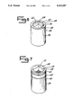
- FIG. 4 is a side plan view illustrating a second preferred embodiment of the apparatus as shown along with line 4--4;
- FIG. 5 is a side plan view partial cut away illustrating the preferred embodiment of FIG. 4 as it is used with a tap apparatus.
- FIG. 6 is a top plan view of the preferred embodiment shown in FIG. 4.
- FIG. 7 is a bottom plan view of the preferred embodiment shown in FIG. 4.
- a socket driveable tap apparatus kit 10 is disclosed.
- the kit 10 is comprised of a plurality of socket tap drives of differing sizes.
- the kit 10 is comprised of eight socket tap drives 12, 14, 16, 18, 20, 22, 24, 26.
- the eight socket tap drives 12, 14, 16, 18, 20, 22, 24, 26 are held in a socket tap drive kit holder 28, commonly made of a thermoplastic material.
- the socket tap drive kit holder 28 is provided with eight pockets 30, 32, 34, 36, 38, 40, 42, 44.
- the first socket tap drive 12 is held in the first pocket 30
- the second socket tap drive 14 is held in the second pocket 32
- the third socket tap drive 16 is held in the third pocket 34
- the fourth socket tap drive 18 is held in the fourth pocket 36
- the fifth socket tap drive 20 is held in the fifth pocket 38
- the sixth socket tap 22 is held in the sixth pocket 40
- the seventh socket tap drive 24 is held in the seventh pocket 42
- the eight socket tap drive 26 is held in the eighth pocket 44.
- the socket tap drive 26 has an exterior cylindrical wall 46, at the top of which is a top ridge 48.
- An O-ring retainer 50 is provided.
- the tap drive 26 has an interior tap wall 52 which in combination with the inner periphery of the top ridge 48, define a tap receiving aperture 54.
- a tap shoulder support shelf 56 At the bottom of the cylindrical shaped tap receiving aperture 54 is a tap shoulder support shelf 56 which defines a tap drive shaft aperture 58 of substantially square cross section.
- the tap drive 26 has an upper circumferential groove 60 and a lower circumferential groove 62.
- the drive 26 is further provided with a bottom ridge 64.
- a socket drive aperture 66 is constructed and arranged for receipt of a standard socket drive (not shown) and is substantially square in cross section.
- a countersink bevel 68 Disposed about the periphery of the socket drive aperture 66 is a countersink bevel 68 which is constructed and arranged to facilitate easy installation and removal of a socket drive.
- a socket drive wall 70 is substantially square in cross section and is of a sufficient height to facilitate receipt of the socket drive (not shown).
- an O-ring crimp ridge 74 is shown.
- a rubber or rubber-like O-ring 50 is slotted in the O-ring receiving groove 92, and the apparatus 26 is crimped so as to provide the O-ring crimp ridge 74 which holds the O-ring 50 in place.
- the O-ring 50, the O-ring receiving groove 92 and the ridge 74 thus provide means for securing a tap drive in the tap receiving aperture 54.
- a socket drive releasing ball groove 76 is provided in the socket drive aperture of the apparatus 26.
- the socket drive releasing ball groove 76 is constructed and arranged to receive a releasing ball provided on a standard socket drive so as to effect release and engagement of the socket drive from the apparatus 10, thus defining means for securing a socket drive in the socket drive aperture 66.
- the tap 78 is provided with a tap tip 80, a square drive base 82 and a cylindrical body 84.
- the tap 78 has a plurality of grooved recesses 86 disposed longitudinally about the axis of the tap 78.
- Cutting teeth 88 are provided which extend substantially perpendicular to the groove recesses 86 and effect cutting of the metal to be tapped.
- a conical point 90 of substantially smooth texture is provided at the upper end of the tap 78, terminating in the tap tip 80.
- the invention therefore provides an improved socket driveable tap apparatus.
- the foregoing detailed description describes a preferred embodiment of the invention. It is clear, however, that the preferred embodiment may be variously modified. Therefore, to particularly point out and distinctly claim the subject matter regarded as invention, the following claims conclude this specification.
Abstract
Description
Claims (5)
Priority Applications (1)
| Application Number | Priority Date | Filing Date | Title |
|---|---|---|---|
| US07/693,445 US5213347A (en) | 1991-04-29 | 1991-04-29 | Socket driveable tap apparatus |
Applications Claiming Priority (1)
| Application Number | Priority Date | Filing Date | Title |
|---|---|---|---|
| US07/693,445 US5213347A (en) | 1991-04-29 | 1991-04-29 | Socket driveable tap apparatus |
Publications (1)
| Publication Number | Publication Date |
|---|---|
| US5213347A true US5213347A (en) | 1993-05-25 |
Family
ID=24784678
Family Applications (1)
| Application Number | Title | Priority Date | Filing Date |
|---|---|---|---|
| US07/693,445 Expired - Lifetime US5213347A (en) | 1991-04-29 | 1991-04-29 | Socket driveable tap apparatus |
Country Status (1)
| Country | Link |
|---|---|
| US (1) | US5213347A (en) |
Cited By (28)
| Publication number | Priority date | Publication date | Assignee | Title |
|---|---|---|---|---|
| WO1996023627A1 (en) * | 1995-02-03 | 1996-08-08 | C.M.E. Blasting & Mining Equipment Ltd. | Grinding cup and holder device |
| US5782570A (en) * | 1995-10-23 | 1998-07-21 | Chicago Pneumatic Tool Company | Alignment of attachment(s) mounted on a power tool |
| US5927411A (en) * | 1997-04-16 | 1999-07-27 | Kennametal Inc. | Connector with variable resistance retention member |
| AU711663B2 (en) * | 1995-02-03 | 1999-10-21 | C.M.E. Blasting & Mining Equipment Ltd. | Grinding cup and holder device |
| US20060175773A1 (en) * | 2004-12-09 | 2006-08-10 | Mobiletron Electronics Co., Ltd. | Adapter for impact rotary tool |
| US20070031202A1 (en) * | 2005-08-05 | 2007-02-08 | Mu Hsien-Chung T | Tap and die ratcheting wrench assembly |
| US20070048099A1 (en) * | 2005-08-26 | 2007-03-01 | Eliot Evans | Thread tap adapter |
| WO2007022930A1 (en) * | 2005-08-22 | 2007-03-01 | MAPAL Fabrik für Präzisionswerkzeuge Dr. Kress KG | Interface element |
| US20070298892A1 (en) * | 2006-06-22 | 2007-12-27 | Steven Carl Leonard | Adaptive drive shank for driving a tap tool with a socket and ratchet |
| US20080217870A1 (en) * | 2007-03-07 | 2008-09-11 | Makita Corporation | Bit mounting devices |
| US20090107303A1 (en) * | 2007-10-30 | 2009-04-30 | Paul Steinweg | Tool locking mechanism |
| US20120051864A1 (en) * | 2010-08-30 | 2012-03-01 | Sudershan Khurana | Drill/countersink assembly and method for producing countersunk holes |
| US20120057946A1 (en) * | 2010-09-08 | 2012-03-08 | Daishowa Seiki Kabushiki Kaisha d/b/a BIG DAISHOWA SEIKI CO LTD | Holding apparatus for cutting tool |
| US20130053975A1 (en) * | 2010-06-02 | 2013-02-28 | Wright Medical Technology, Inc. | Hammer toe implant method |
| US8696267B2 (en) * | 2010-12-20 | 2014-04-15 | Sudershan K Khurana | Drill/countersink assembly and method for producing countersunk holes |
| US8844941B1 (en) * | 2010-06-29 | 2014-09-30 | Ronald W. Dickrede | Adaptor for holding a threading device |
| US20150048576A1 (en) * | 2013-08-13 | 2015-02-19 | Good-Tec Co., Ltd. | Machining Tool Holder With Vibration Preventing Capability and Lubricating Function |
| WO2015140680A1 (en) * | 2014-03-19 | 2015-09-24 | Roggerone Danilo | Bushing for supporting screw taps |
| US9474561B2 (en) | 2013-11-19 | 2016-10-25 | Wright Medical Technology, Inc. | Two-wire technique for installing hammertoe implant |
| US9498266B2 (en) | 2014-02-12 | 2016-11-22 | Wright Medical Technology, Inc. | Intramedullary implant, system, and method for inserting an implant into a bone |
| US9498273B2 (en) | 2010-06-02 | 2016-11-22 | Wright Medical Technology, Inc. | Orthopedic implant kit |
| US9504582B2 (en) | 2012-12-31 | 2016-11-29 | Wright Medical Technology, Inc. | Ball and socket implants for correction of hammer toes and claw toes |
| US9545274B2 (en) | 2014-02-12 | 2017-01-17 | Wright Medical Technology, Inc. | Intramedullary implant, system, and method for inserting an implant into a bone |
| US9603643B2 (en) | 2010-06-02 | 2017-03-28 | Wright Medical Technology, Inc. | Hammer toe implant with expansion portion for retrograde approach |
| US9724140B2 (en) | 2010-06-02 | 2017-08-08 | Wright Medical Technology, Inc. | Tapered, cylindrical cruciform hammer toe implant and method |
| US9724139B2 (en) | 2013-10-01 | 2017-08-08 | Wright Medical Technology, Inc. | Hammer toe implant and method |
| US9808296B2 (en) | 2014-09-18 | 2017-11-07 | Wright Medical Technology, Inc. | Hammertoe implant and instrument |
| US10080597B2 (en) | 2014-12-19 | 2018-09-25 | Wright Medical Technology, Inc. | Intramedullary anchor for interphalangeal arthrodesis |
Citations (7)
| Publication number | Priority date | Publication date | Assignee | Title |
|---|---|---|---|---|
| US1478736A (en) * | 1922-08-10 | 1923-12-25 | John O Gadberry | Socket wrench |
| US2987334A (en) * | 1959-06-22 | 1961-06-06 | Apex Machine & Tool Company | Tool holders |
| US3553753A (en) * | 1968-03-07 | 1971-01-12 | Floyd F Hundley | Tap chuck with overload release |
| US3738768A (en) * | 1971-02-09 | 1973-06-12 | R Kuhn | Tap wrench with swivel drive |
| US4095917A (en) * | 1976-10-01 | 1978-06-20 | Wesner Arden L | Die holder |
| US4111591A (en) * | 1977-08-22 | 1978-09-05 | Gulf & Western Manufacturing Company | Combination tap and die wrench |
| US4770073A (en) * | 1987-02-20 | 1988-09-13 | Bernhard Palm | Socket wrench extension |
-
1991
- 1991-04-29 US US07/693,445 patent/US5213347A/en not_active Expired - Lifetime
Patent Citations (7)
| Publication number | Priority date | Publication date | Assignee | Title |
|---|---|---|---|---|
| US1478736A (en) * | 1922-08-10 | 1923-12-25 | John O Gadberry | Socket wrench |
| US2987334A (en) * | 1959-06-22 | 1961-06-06 | Apex Machine & Tool Company | Tool holders |
| US3553753A (en) * | 1968-03-07 | 1971-01-12 | Floyd F Hundley | Tap chuck with overload release |
| US3738768A (en) * | 1971-02-09 | 1973-06-12 | R Kuhn | Tap wrench with swivel drive |
| US4095917A (en) * | 1976-10-01 | 1978-06-20 | Wesner Arden L | Die holder |
| US4111591A (en) * | 1977-08-22 | 1978-09-05 | Gulf & Western Manufacturing Company | Combination tap and die wrench |
| US4770073A (en) * | 1987-02-20 | 1988-09-13 | Bernhard Palm | Socket wrench extension |
Non-Patent Citations (2)
| Title |
|---|
| Enco "Handtapper", Model 318-0007, shown in catalogue, p. 109. |
| Enco Handtapper , Model 318 0007, shown in catalogue, p. 109. * |
Cited By (44)
| Publication number | Priority date | Publication date | Assignee | Title |
|---|---|---|---|---|
| AU711663B2 (en) * | 1995-02-03 | 1999-10-21 | C.M.E. Blasting & Mining Equipment Ltd. | Grinding cup and holder device |
| WO1996023627A1 (en) * | 1995-02-03 | 1996-08-08 | C.M.E. Blasting & Mining Equipment Ltd. | Grinding cup and holder device |
| US5782570A (en) * | 1995-10-23 | 1998-07-21 | Chicago Pneumatic Tool Company | Alignment of attachment(s) mounted on a power tool |
| US5927411A (en) * | 1997-04-16 | 1999-07-27 | Kennametal Inc. | Connector with variable resistance retention member |
| US20060175773A1 (en) * | 2004-12-09 | 2006-08-10 | Mobiletron Electronics Co., Ltd. | Adapter for impact rotary tool |
| US20070031202A1 (en) * | 2005-08-05 | 2007-02-08 | Mu Hsien-Chung T | Tap and die ratcheting wrench assembly |
| US20110052336A1 (en) * | 2005-08-22 | 2011-03-03 | Dieter Kress | Interface Element |
| US8967928B2 (en) | 2005-08-22 | 2015-03-03 | Mapal Fabrik Fur Prazisionswerkzeuge Dr. Kress Kg | Interface element |
| WO2007022930A1 (en) * | 2005-08-22 | 2007-03-01 | MAPAL Fabrik für Präzisionswerkzeuge Dr. Kress KG | Interface element |
| US7736100B2 (en) | 2005-08-26 | 2010-06-15 | Eliot Evans | Thread tap adapter |
| US20070048099A1 (en) * | 2005-08-26 | 2007-03-01 | Eliot Evans | Thread tap adapter |
| US7442128B2 (en) * | 2006-06-22 | 2008-10-28 | Steven Carl Leonard | Adaptive drive shank for driving a tap tool with a socket and ratchet |
| US20070298892A1 (en) * | 2006-06-22 | 2007-12-27 | Steven Carl Leonard | Adaptive drive shank for driving a tap tool with a socket and ratchet |
| US20080217870A1 (en) * | 2007-03-07 | 2008-09-11 | Makita Corporation | Bit mounting devices |
| US8172236B2 (en) * | 2007-03-07 | 2012-05-08 | Makita Corporation | Bit mounting devices |
| US8813612B2 (en) | 2007-10-30 | 2014-08-26 | Apex Brands, Inc. | Tool locking mechanism |
| US20090107303A1 (en) * | 2007-10-30 | 2009-04-30 | Paul Steinweg | Tool locking mechanism |
| US9975225B2 (en) | 2007-10-30 | 2018-05-22 | Apex Brands, Inc. | Tool locking mechanism |
| US8375831B2 (en) | 2007-10-30 | 2013-02-19 | Easco Hand Tools, Inc. | Tool locking mechanism |
| US10736676B2 (en) | 2010-06-02 | 2020-08-11 | Wright Medical Technology, Inc. | Orthopedic implant kit |
| US9877753B2 (en) | 2010-06-02 | 2018-01-30 | Wright Medical Technology, Inc. | Orthopedic implant kit |
| US9949775B2 (en) | 2010-06-02 | 2018-04-24 | Wright Medical Technology, Inc. | Hammer toe implant with expansion portion for retrograde approach |
| US20130053975A1 (en) * | 2010-06-02 | 2013-02-28 | Wright Medical Technology, Inc. | Hammer toe implant method |
| US9724140B2 (en) | 2010-06-02 | 2017-08-08 | Wright Medical Technology, Inc. | Tapered, cylindrical cruciform hammer toe implant and method |
| US9498273B2 (en) | 2010-06-02 | 2016-11-22 | Wright Medical Technology, Inc. | Orthopedic implant kit |
| US9044287B2 (en) * | 2010-06-02 | 2015-06-02 | Wright Medical Technology, Inc. | Hammer toe implant method |
| US9603643B2 (en) | 2010-06-02 | 2017-03-28 | Wright Medical Technology, Inc. | Hammer toe implant with expansion portion for retrograde approach |
| US8844941B1 (en) * | 2010-06-29 | 2014-09-30 | Ronald W. Dickrede | Adaptor for holding a threading device |
| US20120051864A1 (en) * | 2010-08-30 | 2012-03-01 | Sudershan Khurana | Drill/countersink assembly and method for producing countersunk holes |
| US8651776B2 (en) * | 2010-08-30 | 2014-02-18 | Sudershan Khurana | Drill/countersink assembly and method for producing countersunk holes |
| US20120057946A1 (en) * | 2010-09-08 | 2012-03-08 | Daishowa Seiki Kabushiki Kaisha d/b/a BIG DAISHOWA SEIKI CO LTD | Holding apparatus for cutting tool |
| US8696267B2 (en) * | 2010-12-20 | 2014-04-15 | Sudershan K Khurana | Drill/countersink assembly and method for producing countersunk holes |
| US10278828B2 (en) | 2012-12-31 | 2019-05-07 | Wright Medical Technology, Inc. | Ball and socket implants for correction of hammer toes and claw toes |
| US9504582B2 (en) | 2012-12-31 | 2016-11-29 | Wright Medical Technology, Inc. | Ball and socket implants for correction of hammer toes and claw toes |
| US20150048576A1 (en) * | 2013-08-13 | 2015-02-19 | Good-Tec Co., Ltd. | Machining Tool Holder With Vibration Preventing Capability and Lubricating Function |
| US9724139B2 (en) | 2013-10-01 | 2017-08-08 | Wright Medical Technology, Inc. | Hammer toe implant and method |
| US9675392B2 (en) | 2013-11-19 | 2017-06-13 | Wright Medical Technology, Inc. | Two-wire technique for installing hammertoe implant |
| US9474561B2 (en) | 2013-11-19 | 2016-10-25 | Wright Medical Technology, Inc. | Two-wire technique for installing hammertoe implant |
| US9498266B2 (en) | 2014-02-12 | 2016-11-22 | Wright Medical Technology, Inc. | Intramedullary implant, system, and method for inserting an implant into a bone |
| US9545274B2 (en) | 2014-02-12 | 2017-01-17 | Wright Medical Technology, Inc. | Intramedullary implant, system, and method for inserting an implant into a bone |
| WO2015140680A1 (en) * | 2014-03-19 | 2015-09-24 | Roggerone Danilo | Bushing for supporting screw taps |
| US9808296B2 (en) | 2014-09-18 | 2017-11-07 | Wright Medical Technology, Inc. | Hammertoe implant and instrument |
| US10299840B2 (en) | 2014-09-18 | 2019-05-28 | Wright Medical Technology, Inc. | Hammertoe implant and instrument |
| US10080597B2 (en) | 2014-12-19 | 2018-09-25 | Wright Medical Technology, Inc. | Intramedullary anchor for interphalangeal arthrodesis |
Similar Documents
| Publication | Publication Date | Title |
|---|---|---|
| US5213347A (en) | Socket driveable tap apparatus | |
| US3715168A (en) | Die stock(holder)and extension | |
| US4663998A (en) | Magnetic wrench socket | |
| US4621738A (en) | Holder for wrench sockets | |
| US10843328B2 (en) | Tool organizer and tool organizer module | |
| US3667518A (en) | Screwdriver with bit storing handle | |
| US4631783A (en) | Holding unit | |
| US3227015A (en) | Extending socket wrench | |
| US5435672A (en) | Hole saw having plug ejection feature | |
| US3726393A (en) | Socket wrench retainer and assemblies | |
| US7344346B2 (en) | Fast fasten and loose resistant bolt and nut structure | |
| US7437975B1 (en) | Wrench socket | |
| US4300607A (en) | Variable length tool handle | |
| US4278119A (en) | Storage means for removable tips for hand tool | |
| US5873580A (en) | Tool holder with interchangeable collet/chuck system | |
| US20070082746A1 (en) | Threaded die holder apparatus | |
| US4097182A (en) | Combination tap and die wrench | |
| US4273173A (en) | Device for transmitting torque | |
| DE102014102889A1 (en) | Power tool and power tool accessory | |
| US6305885B1 (en) | Hole enlargement apparatus | |
| DE102006043129A1 (en) | holding assembly | |
| US20010022118A1 (en) | tightening nut for a collect | |
| US4032008A (en) | Tool holder guide indicia for tap and drill sets | |
| US6293173B1 (en) | Tool-bit magazine for hand tool | |
| US5163665A (en) | Universal gripping tool assembly |
Legal Events
| Date | Code | Title | Description |
|---|---|---|---|
| AS | Assignment |
Owner name: LISLE CORPORATION Free format text: ASSIGNMENT OF ASSIGNORS INTEREST.;ASSIGNOR:NEGUS JOEL A.;REEL/FRAME:005777/0674 Effective date: 19910520 Owner name: ALLEGRETTI & WITCOFF, LTD. Free format text: ASSIGNMENT OF ASSIGNORS INTEREST.;ASSIGNOR:RULON RICHARD E.;REEL/FRAME:005777/0671 Effective date: 19910523 |
|
| STCF | Information on status: patent grant |
Free format text: PATENTED CASE |
|
| FPAY | Fee payment |
Year of fee payment: 4 |
|
| FEPP | Fee payment procedure |
Free format text: PAYOR NUMBER ASSIGNED (ORIGINAL EVENT CODE: ASPN); ENTITY STATUS OF PATENT OWNER: SMALL ENTITY |
|
| REMI | Maintenance fee reminder mailed | ||
| FPAY | Fee payment |
Year of fee payment: 8 |
|
| SULP | Surcharge for late payment |
Year of fee payment: 7 |
|
| FPAY | Fee payment |
Year of fee payment: 12 |