US5221069A - Telescoping support bracket - Google Patents
Telescoping support bracket Download PDFInfo
- Publication number
- US5221069A US5221069A US07/881,690 US88169092A US5221069A US 5221069 A US5221069 A US 5221069A US 88169092 A US88169092 A US 88169092A US 5221069 A US5221069 A US 5221069A
- Authority
- US
- United States
- Prior art keywords
- telescoping
- speaker
- support
- exterior
- interior frame
- Prior art date
- Legal status (The legal status is an assumption and is not a legal conclusion. Google has not performed a legal analysis and makes no representation as to the accuracy of the status listed.)
- Expired - Fee Related
Links
Images
Classifications
-
- H—ELECTRICITY
- H04—ELECTRIC COMMUNICATION TECHNIQUE
- H04R—LOUDSPEAKERS, MICROPHONES, GRAMOPHONE PICK-UPS OR LIKE ACOUSTIC ELECTROMECHANICAL TRANSDUCERS; DEAF-AID SETS; PUBLIC ADDRESS SYSTEMS
- H04R1/00—Details of transducers, loudspeakers or microphones
- H04R1/02—Casings; Cabinets ; Supports therefor; Mountings therein
- H04R1/025—Arrangements for fixing loudspeaker transducers, e.g. in a box, furniture
-
- H—ELECTRICITY
- H04—ELECTRIC COMMUNICATION TECHNIQUE
- H04R—LOUDSPEAKERS, MICROPHONES, GRAMOPHONE PICK-UPS OR LIKE ACOUSTIC ELECTROMECHANICAL TRANSDUCERS; DEAF-AID SETS; PUBLIC ADDRESS SYSTEMS
- H04R2201/00—Details of transducers, loudspeakers or microphones covered by H04R1/00 but not provided for in any of its subgroups
- H04R2201/02—Details casings, cabinets or mounting therein for transducers covered by H04R1/02 but not provided for in any of its subgroups
- H04R2201/021—Transducers or their casings adapted for mounting in or to a wall or ceiling
Definitions
- the present invention relates generally to support brackets. It relates more particularly to a telescoping support bracket for mounting speakers and the like into the walls or ceilings of frame-and-wallboard building structures.
- U.S. Pat. No. 4,778,134 issued to STRUTHERS, ET AL. discloses a bracket for mounting speakers in the ceiling or wall.
- the brackets disclosed in that patent use two thin support wings to attach the bracket housing to the framing members. Though suitable for many applications those brackets do not provide for any positional adjustment of the housing within the wall. Consequently the depth of the speaker is set once the support wings are secured to the framing members.
- the present invention specifically addresses and alleviates the above-mentioned deficiencies associated in the prior art. More particularly, the present invention comprises a telescoping speaker support bracket for providing convenient installation of wall mounted speakers and the like.
- the telescoping mount bracket generally comprises a body disposable within an architectural structure such as a wall or ceiling, and a telescoping member movable relative to the body.
- a bezel to which a speaker or like component may be attached, is attached to the telescoping member.
- the telescoping tubular member may be locked at various positions relative to the body via detent means whereby various lengths of the telescoping tube may extend from the body to compensate for various exterior member or wall covering thicknesses.
- the detent means may comprise at least one post formed upon the body and a plurality of slots formed upon the telescoping member for engaging the post. Movement of the mount relative to the body provides depth adjustment such that the body may be attached to the interior of an architectural structure, i.e., framing members or studs, and the component may then be attached to the bezel such that a desired surface of the component is substantially flush with the exterior member or outside surface of the architectural structure.
- a speaker for example, may be quickly mounted with the grill substantially flush to the outside surface of a wall.
- the telescoping mount bracket of the present invention thereby eliminates the need to perform a custom installation wherein custom brackets and/or other fixtures must be fabricated.
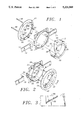
- FIG. 1 is an exploded rear perspective view of the telescoping mount bracket of the present invention
- FIG. 2 is a front perspective view of the telescoping mount bracket of the present invention having the telescoping member disposed within the body;
- FIG. 3 is an enlarged perspective side view of the telescoping member showing the slot detents formed thereupon;
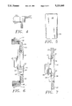
- FIG. 4 is a cross-sectional side view of the bezel of FIG. 2 taken along line 4;
- FIG. 5 is a perspective view of a tab having barbed edges
- FIG. 6 is a cross-sectional top view of the telescoping mount bracket of the present invention having a speaker installed therein and being installed within a wall;
- FIG. 7 is a cross-sectional side view of the installed telescoping mount bracket of FIG. 6.
- FIGS. 1-7 depict a presently preferred embodiment of the invention.
- the telescoping mount bracket is comprised generally of a body 10 and a telescoping tubular member 12 slidably received within a central opening 44 in the body 10.
- Flanges or wings 14, each having an array of apertures 16 formed therein are attachable to the body 10. Attachment of the wings 14 to the body 10 is preferably via sliding engagement of male dovetail members 18 formed upon the wings 14 within female dovetail members 20 formed upon the body 10.
- Those skilled in the art will recognize that various configurations for slidable engagement of the wings 14 and the body 10 are likewise suitable.
- a plurality of slots 22 configured in a stair-step fashion, are positioned about the outer surface of the telescoping tubular member 12 and engage corresponding complimentary projections 24 formed within the central opening 44 of the body 10 to define detents for locking the telescoping tubular member 12 in a desired position relative to the body 10.
- detents for locking the telescoping tubular member 12 in a desired position relative to the body 10.
- Those skilled in the art will recognize that various other detent arrangements are likewise suitable.
- the slots 22 are formed upon elevations 36 which protrude from the telescoping tubular member 12.
- the slots 22 of the telescoping tubular member 12 (as best shown in FIG. 3) lock the telescoping tubular member 12 into position relative to the body 10 once the clamping bolts 38 are tightened as discussed below.
- the slots 22 are formed of sufficient depth that it is thus necessary to slightly retract the telescoping tubular member 12 from the body 10 before effecting rotation thereof for length adjustment.
- the slots 22 and posts 24 thus prevent inadvertent rotation of the telescoping tubular member 12 and consequent inadvertent changes in the length of the telescoping mount bracket.
- the use of slots 22 and post 24 as a detent means provides a positive locking arrangement.
- Bendable tabs 28, best shown in FIG. 5, are formed proximate the distal outer periphery of the telescoping tubular member 12.
- the tabs 28 originally extend in a direction parallel to the axis of the telescoping tubular member 12.
- the tabs 28 may be bent 90 degrees to a position where they extend radially outward.
- the bendable tabs 28 may be formed of a metal such that they are bendable yet will retain their bent configuration during use.
- the tabs 28 are thus suitable for temporarily securing the body 10 and telescoping tubular member 12 in position during installation as described in detail below.
- the tabs 28 may optionally be provided separate from the body 10 and installed into preformed slots within the body 10 as desired. Barbs 34 formed along the lower edges of the tab 28 may be utilized to prevent the tabs 28 from being inadvertently pulled from the body 10.
- a speaker support or bezel 40 is attachable to the tube 12 via fasteners or clamping bolts 38.
- Apertures 30 formed in the bezel 40 receive clamping bolts 38.
- Apertures 32 formed in the bezel 40 facilitate the mounting of a speaker or other component thereto.
- Threaded apertures 26 formed upon a flange 46 extending inwardly from the rearmost periphery of the telescoping tubular member 12 provide for the attachment of the bezel 40 to the telescoping tubular member 12.
- the bezel 40 has a tapered portion 54 (best shown in FIG. 4) and a recess 42 into which a grill (not shown) may be disposed as is common in contemporary wall mount speaker assemblies.
- FIGS. 6 and 7 use of the telescoping mount bracket of the present invention during new construction, i.e., prior to the installation of drywall is illustrated.
- the wings 14 are attached to the body 10 and the telescoping tubular member 12 is inserted therein.
- the body 10 is then positioned at a desired location among the studs 50 of an architectural structure such as a wall or ceiling such that each of the wings 14 extend across a stud 50.
- Fasteners, such as screws or nails 58 are then applied through the apertures 16 and into the studs 50 to secure the wings 14 thereto.
- the tube 12 may be slidably adjusted in or out relative to the wings 14 to provide a degree of depth adjustment.
- the tabs 28 are generally not required during new construction installation since the wings 14 secure the body 10 in place prior to tightening of the clamping bolts 38.
- the telescoping tubular member 12 is adjusted to extend from the body 10 by a length which will position its forward periphery 56 (FIG. 1) flush with the outer surface 53 of the latter installed wall covering 52.
- Plasterboard, or other wall covering 52 forms an exterior member and is then applied over the studs 50 and telescoping mount bracket.
- An aperture is formed by the installer in the plasterboard or other wall covering 52 to receive the telescoping tubular member 12 of the telescoping mount bracket. This aperture is preferably formed prior to applying the wall covering 52 to the studs 50.
- the extension of the telescoping tubular member 12 from the body 10 may be readjusted as necessary after the wall covering 52 is applied such that the forward periphery 56 is flush with the outer surface 53 of the wall covering 52.
- a bezel 40 is attached to the tube 12 via clamping bolts 38 of sufficient length to span the distance between the bezel apertures 30 and the threaded apertures 26.
- the bezel 40 is adapted to attach a desired component such as a speaker thereto.
- a generally round aperture of sufficient size to receive the body 10 with the telescoping tubular member 12 received therein is first made within the exterior member or drywall of the architectural structure.
- the opening is sized to receive the body 10 and telescoping tubular member 12 when the generally planar rectangular body 10 is oriented substantially perpendicularly to the wall covering and not to pass the body 10 and telescoping tubular member 12 therethrough when the body 10 is oriented substantially parallel thereto, such that the body 10 may be inserted through the opening and rotated 90 degrees to prevent its removal.
- the rotated position is the substantially parallel position illustrated in FIGS. 6 and 7.
- the body 10 and telescoping tubular member 12 are passed through the aperture and the body 10 is held flush to the inner surface of the wall covering.
- the telescoping tubular member 12 is then adjusted such that its outermost surface or forward periphery 56 is flush with the outer surface 53 of the exterior member or wall covering 52.
- the tabs 28 are then bent outward to prevent the body 10 and telescoping tubular member 12 from falling inward.
- the wings 14 will generally not be utilized in the installation of the telescoping mount bracket of the present invention into a prior constructed architectural structure since this would involve removal and replacement of a large portion of drywall. Rather, the body 10 and telescoping tubular member 12 are initially secured in place via tabs 28. Next, the clamping bolts 38 are inserted through the clamping bolt apertures 30 in the bezel 40 and the bezel 40 is then attached to the tube 12 by further inserting the clamping bolts 38 through the threaded clamping bolt apertures 26 of the telescoping tubular member 12. Tightening the clamping bolts 38 thus captures a portion of the drywall or wall covering 52 as described previously and illustrated in FIGS. 6 and 7.
- a component such as a stereo speaker 48 may be attached thereto.
- a component such as a stereo speaker 48 may be attached thereto.
- various components e.g., lights, controls, or works of art, may likewise be installed within an architectural structure utilizing the telescoping mount bracket of the present invention.
- the component is generally secured to the bezel 40 by inserting fasteners such as screws through the component and into the threaded mount apertures 32.
- a screw thread arrangement may be utilized to affect telescoping as opposed to the post and stair step detent arrangement discussed above. That is, complimentary screw threads could be formed upon the tubular member 12 and the body 10 such that rotation of the tubular member 12 relative to the body 10 results in extension of the tubular member 12 therefrom. Thus, as the tubular member 12 is rotated it screws itself into or out of the body 10 in the same manner that a bolt screws into or out of a threaded hole.
Abstract
Description
Claims (20)
Priority Applications (1)
| Application Number | Priority Date | Filing Date | Title |
|---|---|---|---|
| US07/881,690 US5221069A (en) | 1992-05-12 | 1992-05-12 | Telescoping support bracket |
Applications Claiming Priority (1)
| Application Number | Priority Date | Filing Date | Title |
|---|---|---|---|
| US07/881,690 US5221069A (en) | 1992-05-12 | 1992-05-12 | Telescoping support bracket |
Publications (1)
| Publication Number | Publication Date |
|---|---|
| US5221069A true US5221069A (en) | 1993-06-22 |
Family
ID=25378988
Family Applications (1)
| Application Number | Title | Priority Date | Filing Date |
|---|---|---|---|
| US07/881,690 Expired - Fee Related US5221069A (en) | 1992-05-12 | 1992-05-12 | Telescoping support bracket |
Country Status (1)
| Country | Link |
|---|---|
| US (1) | US5221069A (en) |
Cited By (34)
| Publication number | Priority date | Publication date | Assignee | Title |
|---|---|---|---|---|
| US5292092A (en) * | 1993-04-26 | 1994-03-08 | Dana Innovations | Retrofit bracket for wall mount speakers |
| US5310149A (en) * | 1993-05-25 | 1994-05-10 | Dana Innovations | Depth adjustable bracket for wall mount speakers |
| US5330144A (en) * | 1993-01-08 | 1994-07-19 | Square D Company | Frame structure and assembly for wall mounting a speaker or camera |
| US5423500A (en) * | 1993-07-06 | 1995-06-13 | Dana Innovatins | Flat bracket for wall mount speakers |
| US5660364A (en) * | 1996-05-30 | 1997-08-26 | Hsieh; Wu Hong | Tom-tom holder |
| US5725190A (en) * | 1994-12-15 | 1998-03-10 | Hunter Fan Company | Sloped ceiling adaptor |
| US6145795A (en) * | 1999-02-26 | 2000-11-14 | Sheerlund Products, Inc. | Pumpkin stand |
| US6186459B1 (en) * | 1998-11-12 | 2001-02-13 | His-Kuang Ma | Angle/direction adjustable display device |
| US6474846B1 (en) * | 1999-03-05 | 2002-11-05 | Victor Kelmelis | Flush trim collar lighting system |
| US20030123679A1 (en) * | 2002-01-02 | 2003-07-03 | Dudleston William R. | In-wall loudspeaker |
| US6588543B1 (en) | 2001-09-04 | 2003-07-08 | Audio Products International Corp. | Spring-loaded dog assembly which enables a bezel of a speaker system and structure holding electric device to be mounted in ceilings and walls without having to use external retaining means |
| US6758451B2 (en) | 2002-02-15 | 2004-07-06 | Ksc Industries, Inc. | Folding speaker bracket |
| US20040179710A1 (en) * | 2002-12-20 | 2004-09-16 | Farinelli Robert P. | Audio speaker system |
| US20040221522A1 (en) * | 2003-05-09 | 2004-11-11 | HENDRICKS Robert | Single piece mounting frame |
| US20050108893A1 (en) * | 2003-11-26 | 2005-05-26 | Hwang Sung G. | Dryer |
| US20050183344A1 (en) * | 2003-11-12 | 2005-08-25 | Ziobro David J. | Recessed plaster collar assembly |
| US20060231326A1 (en) * | 2003-01-21 | 2006-10-19 | Toa Corporation | Mounting support device for ceiling embedded speaker system |
| US20070051862A1 (en) * | 2005-09-08 | 2007-03-08 | Monti Daniel J | Frameless compression component mounts and quick release speaker frames |
| WO2007087530A2 (en) * | 2006-01-26 | 2007-08-02 | Jimmy Lee Murray | Universal installation template and method of use for placement of in-wall or in-ceiling speakers |
| US20070209819A1 (en) * | 2006-03-07 | 2007-09-13 | Punch Shyr | Mounting bracket |
| US20080035417A1 (en) * | 2006-08-08 | 2008-02-14 | Christopher Combest | Balanced Cantilever Spring Bracket |
| US20080067309A1 (en) * | 2006-09-14 | 2008-03-20 | Serge Taba | Wall Mounting Bracket With Slidable Wing |
| US20080075297A1 (en) * | 2006-09-11 | 2008-03-27 | Dana Innovations | Devices And Methods For Flangeless Installations |
| US20080078903A1 (en) * | 2006-09-11 | 2008-04-03 | Dana Innovations | Devices And Methods For Flangeless Installations |
| US20080224006A1 (en) * | 2007-03-12 | 2008-09-18 | Dana Innovations | Mounting System For Flush Assembly in Walls and Ceilings in Walls And Ceilings |
| US20090095861A1 (en) * | 2006-09-14 | 2009-04-16 | Dana Innovations | Wall mounting bracket with slidable wing |
| US20120292458A1 (en) * | 2011-05-18 | 2012-11-22 | Liang-Chih Cheng | Easy-mount in-ceiling speaker mount |
| US20130043671A1 (en) * | 2011-08-18 | 2013-02-21 | Rodney James Harman | Termination collar for air duct |
| US8839578B2 (en) | 2006-09-11 | 2014-09-23 | Dana Innovations | Flush mount panels with multiple aligned receiving brackets |
| US8881468B2 (en) | 2008-09-19 | 2014-11-11 | Tapco International Corporation | Fixture wall mount assembly with integral flashing |
| US9383087B2 (en) | 2014-03-05 | 2016-07-05 | Elite Lighting | Adjustable recessed light fixture |
| USD797611S1 (en) * | 2015-05-29 | 2017-09-19 | Ciro, LLC | Motorcycle speaker accent assembly |
| US9982802B1 (en) | 2017-05-09 | 2018-05-29 | Jeremy Patterson | Conduit support bracket system |
| US10406674B2 (en) | 2016-08-16 | 2019-09-10 | Origin Acoustics | Removable/re-usable bracket |
Citations (6)
| Publication number | Priority date | Publication date | Assignee | Title |
|---|---|---|---|---|
| US3912865A (en) * | 1973-07-13 | 1975-10-14 | American Trading & Prod | Loudspeaker arrangement |
| US4778134A (en) * | 1987-08-20 | 1988-10-18 | Dana Innovations | Speaker wall bracket |
| US4815558A (en) * | 1985-11-23 | 1989-03-28 | U.S. Philips Corp. | Device for accomodating a loudspeaker into a cut-out of a sound panel |
| US4853966A (en) * | 1987-10-29 | 1989-08-01 | Skrzycki Gary E | Speaker mounting system |
| US5082083A (en) * | 1990-10-02 | 1992-01-21 | Culver Electronic Sales, Inc. | Structure wall mounted speaker assembly |
| US5143339A (en) * | 1991-03-01 | 1992-09-01 | Jbl, Incorporated | Speaker mounting assembly |
-
1992
- 1992-05-12 US US07/881,690 patent/US5221069A/en not_active Expired - Fee Related
Patent Citations (6)
| Publication number | Priority date | Publication date | Assignee | Title |
|---|---|---|---|---|
| US3912865A (en) * | 1973-07-13 | 1975-10-14 | American Trading & Prod | Loudspeaker arrangement |
| US4815558A (en) * | 1985-11-23 | 1989-03-28 | U.S. Philips Corp. | Device for accomodating a loudspeaker into a cut-out of a sound panel |
| US4778134A (en) * | 1987-08-20 | 1988-10-18 | Dana Innovations | Speaker wall bracket |
| US4853966A (en) * | 1987-10-29 | 1989-08-01 | Skrzycki Gary E | Speaker mounting system |
| US5082083A (en) * | 1990-10-02 | 1992-01-21 | Culver Electronic Sales, Inc. | Structure wall mounted speaker assembly |
| US5143339A (en) * | 1991-03-01 | 1992-09-01 | Jbl, Incorporated | Speaker mounting assembly |
Cited By (54)
| Publication number | Priority date | Publication date | Assignee | Title |
|---|---|---|---|---|
| US5330144A (en) * | 1993-01-08 | 1994-07-19 | Square D Company | Frame structure and assembly for wall mounting a speaker or camera |
| US5292092A (en) * | 1993-04-26 | 1994-03-08 | Dana Innovations | Retrofit bracket for wall mount speakers |
| US5310149A (en) * | 1993-05-25 | 1994-05-10 | Dana Innovations | Depth adjustable bracket for wall mount speakers |
| US5388795A (en) * | 1993-05-25 | 1995-02-14 | Dana Innovations | Depth adjustable bracket for wall mount speakers |
| US5423500A (en) * | 1993-07-06 | 1995-06-13 | Dana Innovatins | Flat bracket for wall mount speakers |
| US5725190A (en) * | 1994-12-15 | 1998-03-10 | Hunter Fan Company | Sloped ceiling adaptor |
| US5660364A (en) * | 1996-05-30 | 1997-08-26 | Hsieh; Wu Hong | Tom-tom holder |
| US6186459B1 (en) * | 1998-11-12 | 2001-02-13 | His-Kuang Ma | Angle/direction adjustable display device |
| US6145795A (en) * | 1999-02-26 | 2000-11-14 | Sheerlund Products, Inc. | Pumpkin stand |
| US6422525B1 (en) | 1999-02-26 | 2002-07-23 | Sheerlund Products, Inc. | Pumpkin stand |
| US6474846B1 (en) * | 1999-03-05 | 2002-11-05 | Victor Kelmelis | Flush trim collar lighting system |
| US6588543B1 (en) | 2001-09-04 | 2003-07-08 | Audio Products International Corp. | Spring-loaded dog assembly which enables a bezel of a speaker system and structure holding electric device to be mounted in ceilings and walls without having to use external retaining means |
| US20030123679A1 (en) * | 2002-01-02 | 2003-07-03 | Dudleston William R. | In-wall loudspeaker |
| US6758451B2 (en) | 2002-02-15 | 2004-07-06 | Ksc Industries, Inc. | Folding speaker bracket |
| US20040179710A1 (en) * | 2002-12-20 | 2004-09-16 | Farinelli Robert P. | Audio speaker system |
| US20060231326A1 (en) * | 2003-01-21 | 2006-10-19 | Toa Corporation | Mounting support device for ceiling embedded speaker system |
| US7401681B2 (en) * | 2003-01-21 | 2008-07-22 | Toa Corportion | Mounting support device for ceiling embedded speaker system |
| US20040221522A1 (en) * | 2003-05-09 | 2004-11-11 | HENDRICKS Robert | Single piece mounting frame |
| US7510153B2 (en) * | 2003-05-09 | 2009-03-31 | Tapco International Corporation | Single piece mounting frame |
| US20050183344A1 (en) * | 2003-11-12 | 2005-08-25 | Ziobro David J. | Recessed plaster collar assembly |
| US20090196053A1 (en) * | 2003-11-12 | 2009-08-06 | Cooper Technologies Company | Recessed Plaster Collar Assembly |
| US7571570B2 (en) | 2003-11-12 | 2009-08-11 | Cooper Technologies Company | Recessed plaster collar assembly |
| US7827737B2 (en) | 2003-11-12 | 2010-11-09 | Cooper Technologies Company | Recessed plaster collar assembly |
| US20050108893A1 (en) * | 2003-11-26 | 2005-05-26 | Hwang Sung G. | Dryer |
| US7434334B2 (en) * | 2003-11-26 | 2008-10-14 | Lg Electronics Inc. | Dryer with back cover first and second tab latches |
| US20070051862A1 (en) * | 2005-09-08 | 2007-03-08 | Monti Daniel J | Frameless compression component mounts and quick release speaker frames |
| US7455272B2 (en) | 2005-09-08 | 2008-11-25 | Architectural Audio/Video | Frameless compression component mounts and quick release speaker frames |
| WO2007087530A3 (en) * | 2006-01-26 | 2007-11-29 | Jimmy Lee Murray | Universal installation template and method of use for placement of in-wall or in-ceiling speakers |
| WO2007087530A2 (en) * | 2006-01-26 | 2007-08-02 | Jimmy Lee Murray | Universal installation template and method of use for placement of in-wall or in-ceiling speakers |
| US7285722B2 (en) * | 2006-03-07 | 2007-10-23 | P-Sun International Co., Ltd. | Mounting bracket |
| US20070209819A1 (en) * | 2006-03-07 | 2007-09-13 | Punch Shyr | Mounting bracket |
| US20080035417A1 (en) * | 2006-08-08 | 2008-02-14 | Christopher Combest | Balanced Cantilever Spring Bracket |
| US7654361B2 (en) * | 2006-08-08 | 2010-02-02 | Induction Dynamics Llc | Balanced cantilever spring bracket |
| US20080078903A1 (en) * | 2006-09-11 | 2008-04-03 | Dana Innovations | Devices And Methods For Flangeless Installations |
| US8839578B2 (en) | 2006-09-11 | 2014-09-23 | Dana Innovations | Flush mount panels with multiple aligned receiving brackets |
| US20080075297A1 (en) * | 2006-09-11 | 2008-03-27 | Dana Innovations | Devices And Methods For Flangeless Installations |
| US7699138B2 (en) * | 2006-09-11 | 2010-04-20 | Dana Innovations | Devices and methods for flangeless installations |
| US20110138739A1 (en) * | 2006-09-11 | 2011-06-16 | Scott Struthers | Devices And Methods For Flangeless Installations |
| US8250830B2 (en) | 2006-09-11 | 2012-08-28 | Dana Innovations | Devices and methods for flangeless installations |
| US7461483B2 (en) * | 2006-09-11 | 2008-12-09 | Dana Innovations | Devices and methods for flangeless installations |
| US20090095861A1 (en) * | 2006-09-14 | 2009-04-16 | Dana Innovations | Wall mounting bracket with slidable wing |
| US7665700B2 (en) * | 2006-09-14 | 2010-02-23 | Dana Innovations | Wall mounting bracket with slidable wing |
| US20080067309A1 (en) * | 2006-09-14 | 2008-03-20 | Serge Taba | Wall Mounting Bracket With Slidable Wing |
| WO2008112285A1 (en) * | 2007-03-12 | 2008-09-18 | Dana Innovations | Universal mounting system for flush assembly in walls and ceilings |
| US20080224006A1 (en) * | 2007-03-12 | 2008-09-18 | Dana Innovations | Mounting System For Flush Assembly in Walls and Ceilings in Walls And Ceilings |
| US8881468B2 (en) | 2008-09-19 | 2014-11-11 | Tapco International Corporation | Fixture wall mount assembly with integral flashing |
| US8485487B2 (en) * | 2011-05-18 | 2013-07-16 | Liang-Chih Cheng | Easy-mount in-ceiling speaker mount |
| US20120292458A1 (en) * | 2011-05-18 | 2012-11-22 | Liang-Chih Cheng | Easy-mount in-ceiling speaker mount |
| US8833013B2 (en) * | 2011-08-18 | 2014-09-16 | Rodney James Harman | Termination collar for air duct |
| US20130043671A1 (en) * | 2011-08-18 | 2013-02-21 | Rodney James Harman | Termination collar for air duct |
| US9383087B2 (en) | 2014-03-05 | 2016-07-05 | Elite Lighting | Adjustable recessed light fixture |
| USD797611S1 (en) * | 2015-05-29 | 2017-09-19 | Ciro, LLC | Motorcycle speaker accent assembly |
| US10406674B2 (en) | 2016-08-16 | 2019-09-10 | Origin Acoustics | Removable/re-usable bracket |
| US9982802B1 (en) | 2017-05-09 | 2018-05-29 | Jeremy Patterson | Conduit support bracket system |
Similar Documents
| Publication | Publication Date | Title |
|---|---|---|
| US5221069A (en) | Telescoping support bracket | |
| US8632040B2 (en) | Low profile mounting of electronic devices | |
| US4778134A (en) | Speaker wall bracket | |
| US6573446B1 (en) | Apparatus for mounting an electrical component on a structure | |
| US5823664A (en) | Recessed lighting fixture | |
| US5221814A (en) | Blind mounting face plate and anchor means | |
| US5310149A (en) | Depth adjustable bracket for wall mount speakers | |
| US20140224792A1 (en) | Adjustable wall enclosure for electrical devices and the like | |
| US6164475A (en) | Electrical box for fan or fixture support | |
| US6595478B2 (en) | Curtain rod support system | |
| US20080224006A1 (en) | Mounting System For Flush Assembly in Walls and Ceilings in Walls And Ceilings | |
| WO2011082228A1 (en) | Recessed mount with stowed clamps | |
| JPH08507579A (en) | Coated panel | |
| US5463533A (en) | Variable depth load center enclosure | |
| US4903928A (en) | Bracket arrangement | |
| US20050093407A1 (en) | Apparatus and methods for adjustably mounting a faceplate on a drawer | |
| US20080067309A1 (en) | Wall Mounting Bracket With Slidable Wing | |
| GB2592852A (en) | Electrical component enclosures for recessed mounting | |
| US6802656B2 (en) | Retained hardware system and method | |
| US7060899B1 (en) | Pre-wiring assembly system and method | |
| EP0491010A1 (en) | A method for joining two structural members by the aid of an adjustable fastener, and a mounting for use with said method. | |
| US9935438B2 (en) | Door chime assembly | |
| HU220350B (en) | Link structure and method for fastening a pipe | |
| US4874334A (en) | Electrical outlet positioner | |
| JPH0526166Y2 (en) |
Legal Events
| Date | Code | Title | Description |
|---|---|---|---|
| AS | Assignment |
Owner name: DANA INNOVATIONS, INC., CALIFORNIA Free format text: ASSIGNMENT OF ASSIGNORS INTEREST.;ASSIGNORS:STRUTHERS, SCOTT;KINDEL, WILLIAM J.;MAURER, RONALD D.;AND OTHERS;REEL/FRAME:006120/0703 Effective date: 19920505 |
|
| FPAY | Fee payment |
Year of fee payment: 4 |
|
| REMI | Maintenance fee reminder mailed | ||
| LAPS | Lapse for failure to pay maintenance fees | ||
| FP | Lapsed due to failure to pay maintenance fee |
Effective date: 20010622 |
|
| AS | Assignment |
Owner name: UNION BANK, N.A., CALIFORNIA Free format text: SECURITY AGREEMENT;ASSIGNOR:DANA INNOVATIONS;REEL/FRAME:022990/0051 Effective date: 20090715 Owner name: UNION BANK, N.A.,CALIFORNIA Free format text: SECURITY AGREEMENT;ASSIGNOR:DANA INNOVATIONS;REEL/FRAME:022990/0051 Effective date: 20090715 |
|
| STCH | Information on status: patent discontinuation |
Free format text: PATENT EXPIRED DUE TO NONPAYMENT OF MAINTENANCE FEES UNDER 37 CFR 1.362 |
|
| AS | Assignment |
Owner name: DANA INNOVATIONS, CALIFORNIA Free format text: RELEASE BY SECURED PARTY;ASSIGNOR:MUFG UNION BANK, N.A.;REEL/FRAME:060257/0611 Effective date: 20220616 |