US5230459A - Method of bonding a sputter target-backing plate assembly assemblies produced thereby - Google Patents
Method of bonding a sputter target-backing plate assembly assemblies produced thereby Download PDFInfo
- Publication number
- US5230459A US5230459A US07/853,095 US85309592A US5230459A US 5230459 A US5230459 A US 5230459A US 85309592 A US85309592 A US 85309592A US 5230459 A US5230459 A US 5230459A
- Authority
- US
- United States
- Prior art keywords
- target
- assembly
- backing plate
- recited
- alloy
- Prior art date
- Legal status (The legal status is an assumption and is not a legal conclusion. Google has not performed a legal analysis and makes no representation as to the accuracy of the status listed.)
- Expired - Lifetime
Links
- 238000000034 method Methods 0.000 title claims abstract description 40
- 230000000712 assembly Effects 0.000 title abstract description 9
- 238000000429 assembly Methods 0.000 title abstract description 9
- 229910052751 metal Inorganic materials 0.000 claims abstract description 17
- 239000002184 metal Substances 0.000 claims abstract description 17
- 238000002844 melting Methods 0.000 claims abstract description 11
- 230000008018 melting Effects 0.000 claims abstract description 11
- 238000004320 controlled atmosphere Methods 0.000 claims abstract description 5
- 229910045601 alloy Inorganic materials 0.000 claims abstract 4
- 239000000956 alloy Substances 0.000 claims abstract 4
- 230000013011 mating Effects 0.000 claims description 8
- 238000003825 pressing Methods 0.000 claims description 8
- RYGMFSIKBFXOCR-UHFFFAOYSA-N Copper Chemical compound [Cu] RYGMFSIKBFXOCR-UHFFFAOYSA-N 0.000 claims description 7
- 229910052782 aluminium Inorganic materials 0.000 claims description 7
- XAGFODPZIPBFFR-UHFFFAOYSA-N aluminium Chemical compound [Al] XAGFODPZIPBFFR-UHFFFAOYSA-N 0.000 claims description 7
- 229910052802 copper Inorganic materials 0.000 claims description 7
- 239000010949 copper Substances 0.000 claims description 7
- 238000005304 joining Methods 0.000 claims description 6
- RTAQQCXQSZGOHL-UHFFFAOYSA-N Titanium Chemical compound [Ti] RTAQQCXQSZGOHL-UHFFFAOYSA-N 0.000 claims description 5
- 229910052719 titanium Inorganic materials 0.000 claims description 5
- 239000010936 titanium Substances 0.000 claims description 5
- 229910000881 Cu alloy Inorganic materials 0.000 claims description 4
- 239000010970 precious metal Substances 0.000 claims description 4
- ZOKXTWBITQBERF-UHFFFAOYSA-N Molybdenum Chemical compound [Mo] ZOKXTWBITQBERF-UHFFFAOYSA-N 0.000 claims description 3
- 229910052750 molybdenum Inorganic materials 0.000 claims description 3
- 239000011733 molybdenum Substances 0.000 claims description 3
- 229910052737 gold Inorganic materials 0.000 claims description 2
- 229910052741 iridium Inorganic materials 0.000 claims description 2
- 229910052763 palladium Inorganic materials 0.000 claims description 2
- 229910052697 platinum Inorganic materials 0.000 claims description 2
- 229910052703 rhodium Inorganic materials 0.000 claims description 2
- 229910052707 ruthenium Inorganic materials 0.000 claims description 2
- 238000010438 heat treatment Methods 0.000 claims 7
- 229910000838 Al alloy Inorganic materials 0.000 claims 2
- 229910001182 Mo alloy Inorganic materials 0.000 claims 1
- 229910001069 Ti alloy Inorganic materials 0.000 claims 1
- 229910000923 precious metal alloy Inorganic materials 0.000 claims 1
- 230000008569 process Effects 0.000 abstract description 3
- 239000000463 material Substances 0.000 description 18
- 238000004544 sputter deposition Methods 0.000 description 14
- 229910000679 solder Inorganic materials 0.000 description 8
- 238000009792 diffusion process Methods 0.000 description 7
- 239000007787 solid Substances 0.000 description 7
- 239000000758 substrate Substances 0.000 description 6
- 238000000576 coating method Methods 0.000 description 5
- 239000010408 film Substances 0.000 description 5
- 239000013077 target material Substances 0.000 description 5
- 239000002360 explosive Substances 0.000 description 4
- 239000007789 gas Substances 0.000 description 4
- 239000011261 inert gas Substances 0.000 description 4
- 238000000151 deposition Methods 0.000 description 3
- 230000005684 electric field Effects 0.000 description 3
- 238000001513 hot isostatic pressing Methods 0.000 description 3
- 238000010849 ion bombardment Methods 0.000 description 3
- 150000002500 ions Chemical class 0.000 description 3
- 238000003466 welding Methods 0.000 description 3
- XKRFYHLGVUSROY-UHFFFAOYSA-N Argon Chemical compound [Ar] XKRFYHLGVUSROY-UHFFFAOYSA-N 0.000 description 2
- IJGRMHOSHXDMSA-UHFFFAOYSA-N Atomic nitrogen Chemical compound N#N IJGRMHOSHXDMSA-UHFFFAOYSA-N 0.000 description 2
- 229910000831 Steel Inorganic materials 0.000 description 2
- 238000013459 approach Methods 0.000 description 2
- QVGXLLKOCUKJST-UHFFFAOYSA-N atomic oxygen Chemical compound [O] QVGXLLKOCUKJST-UHFFFAOYSA-N 0.000 description 2
- 230000015572 biosynthetic process Effects 0.000 description 2
- 238000004140 cleaning Methods 0.000 description 2
- 230000003749 cleanliness Effects 0.000 description 2
- 239000011248 coating agent Substances 0.000 description 2
- 230000008021 deposition Effects 0.000 description 2
- 238000009713 electroplating Methods 0.000 description 2
- 239000011888 foil Substances 0.000 description 2
- 238000012986 modification Methods 0.000 description 2
- 230000004048 modification Effects 0.000 description 2
- 239000001301 oxygen Substances 0.000 description 2
- 229910052760 oxygen Inorganic materials 0.000 description 2
- 238000002360 preparation method Methods 0.000 description 2
- 238000005476 soldering Methods 0.000 description 2
- 238000005477 sputtering target Methods 0.000 description 2
- 239000010959 steel Substances 0.000 description 2
- 239000010409 thin film Substances 0.000 description 2
- 230000009471 action Effects 0.000 description 1
- 230000001464 adherent effect Effects 0.000 description 1
- 230000002411 adverse Effects 0.000 description 1
- 229910052786 argon Inorganic materials 0.000 description 1
- 238000005219 brazing Methods 0.000 description 1
- 230000008859 change Effects 0.000 description 1
- 238000004581 coalescence Methods 0.000 description 1
- 238000011109 contamination Methods 0.000 description 1
- 230000008602 contraction Effects 0.000 description 1
- 239000002826 coolant Substances 0.000 description 1
- 238000001816 cooling Methods 0.000 description 1
- 239000012809 cooling fluid Substances 0.000 description 1
- 238000011161 development Methods 0.000 description 1
- 230000000694 effects Effects 0.000 description 1
- 238000007772 electroless plating Methods 0.000 description 1
- 229920006333 epoxy cement Polymers 0.000 description 1
- PCHJSUWPFVWCPO-UHFFFAOYSA-N gold Chemical compound [Au] PCHJSUWPFVWCPO-UHFFFAOYSA-N 0.000 description 1
- 239000010931 gold Substances 0.000 description 1
- 230000006872 improvement Effects 0.000 description 1
- 239000012535 impurity Substances 0.000 description 1
- 230000002401 inhibitory effect Effects 0.000 description 1
- 230000000977 initiatory effect Effects 0.000 description 1
- 230000001788 irregular Effects 0.000 description 1
- 238000003754 machining Methods 0.000 description 1
- 238000001755 magnetron sputter deposition Methods 0.000 description 1
- 238000012423 maintenance Methods 0.000 description 1
- 229910044991 metal oxide Inorganic materials 0.000 description 1
- 150000004706 metal oxides Chemical class 0.000 description 1
- 150000002739 metals Chemical class 0.000 description 1
- 238000013508 migration Methods 0.000 description 1
- 230000005012 migration Effects 0.000 description 1
- 239000000203 mixture Substances 0.000 description 1
- 229910052757 nitrogen Inorganic materials 0.000 description 1
- 230000001681 protective effect Effects 0.000 description 1
- 239000000126 substance Substances 0.000 description 1
- 238000012546 transfer Methods 0.000 description 1
- 238000007740 vapor deposition Methods 0.000 description 1
Images

Classifications
-
- C—CHEMISTRY; METALLURGY
- C23—COATING METALLIC MATERIAL; COATING MATERIAL WITH METALLIC MATERIAL; CHEMICAL SURFACE TREATMENT; DIFFUSION TREATMENT OF METALLIC MATERIAL; COATING BY VACUUM EVAPORATION, BY SPUTTERING, BY ION IMPLANTATION OR BY CHEMICAL VAPOUR DEPOSITION, IN GENERAL; INHIBITING CORROSION OF METALLIC MATERIAL OR INCRUSTATION IN GENERAL
- C23C—COATING METALLIC MATERIAL; COATING MATERIAL WITH METALLIC MATERIAL; SURFACE TREATMENT OF METALLIC MATERIAL BY DIFFUSION INTO THE SURFACE, BY CHEMICAL CONVERSION OR SUBSTITUTION; COATING BY VACUUM EVAPORATION, BY SPUTTERING, BY ION IMPLANTATION OR BY CHEMICAL VAPOUR DEPOSITION, IN GENERAL
- C23C14/00—Coating by vacuum evaporation, by sputtering or by ion implantation of the coating forming material
- C23C14/22—Coating by vacuum evaporation, by sputtering or by ion implantation of the coating forming material characterised by the process of coating
- C23C14/34—Sputtering
- C23C14/3407—Cathode assembly for sputtering apparatus, e.g. Target
-
- B—PERFORMING OPERATIONS; TRANSPORTING
- B23—MACHINE TOOLS; METAL-WORKING NOT OTHERWISE PROVIDED FOR
- B23K—SOLDERING OR UNSOLDERING; WELDING; CLADDING OR PLATING BY SOLDERING OR WELDING; CUTTING BY APPLYING HEAT LOCALLY, e.g. FLAME CUTTING; WORKING BY LASER BEAM
- B23K20/00—Non-electric welding by applying impact or other pressure, with or without the application of heat, e.g. cladding or plating
- B23K20/02—Non-electric welding by applying impact or other pressure, with or without the application of heat, e.g. cladding or plating by means of a press ; Diffusion bonding
- B23K20/023—Thermo-compression bonding
-
- B—PERFORMING OPERATIONS; TRANSPORTING
- B23—MACHINE TOOLS; METAL-WORKING NOT OTHERWISE PROVIDED FOR
- B23K—SOLDERING OR UNSOLDERING; WELDING; CLADDING OR PLATING BY SOLDERING OR WELDING; CUTTING BY APPLYING HEAT LOCALLY, e.g. FLAME CUTTING; WORKING BY LASER BEAM
- B23K20/00—Non-electric welding by applying impact or other pressure, with or without the application of heat, e.g. cladding or plating
- B23K20/14—Preventing or minimising gas access, or using protective gases or vacuum during welding
Abstract
Methods of preparing a sputter target/backing plate assembly and assemblies so prepared are disclosed. The methods comprise forming a plurality of grooves in one of the metal surfaces to be joined in the bonding process. The grooves are each provided in a closed, loop configuration or pattern. The target and backing plate to be bonded are adjacently positioned to form an assembly with the grooved surface forming one of the interfacial joint surfaces. The assembly is then placed in a controlled atmosphere, such as a vacuum, heated to a temperature just below the melting point of the lower melting metal to be joined, and pressed until the grooves are substantially filled with metal or alloy from the other, non-grooved interfacial surface.
Description
The invention pertains to a method of bonding together components of a sputter target-backing plate assembly and to target-backing plate assemblies so produced.
Cathodic sputtering is widely used for the deposition of thin layers of material onto desired substrates. Basically, this process requires a gas ion bombardment of the target having a face formed of a desired material that is to be deposited as a thin film or layer on a substrate. Ion bombardment of the target not only causes atoms or molecules of the target material to be sputtered, but imparts considerable thermal energy to the target. This heat is dissipated by use of a cooling fluid typically circulated beneath or around a backing plate that is positioned in heat exchange relation with the target.
The target forms a part of a cathode assembly which together with an anode is placed in an evacuated chamber that contains an inert gas, preferably argon. A high voltage electrical field is applied across the cathode and anode. The inert gas is ionized by collision with the electrons ejected from the cathode. Positively charged gas ions are attracted to the cathode and, upon impingement with the target surface, dislodge the target material. The dislodged target materials traverse the evacuated enclosure and deposit as a thin film on the desired substrate that is normally located proximate the anode.
In addition to the use of an electrical field, increasing sputtering rates have been achieved by the concurrent use of an arch-shaped magnetic field that is superimposed over the electrical field and formed in a closed loop configuration over the surface of the target. These methods are known as magnetron sputtering methods. The arch-shaped magnetic field traps electrons in an annular region adjacent the target surface thereby increasing the number of electron-gas atom collisions in the area to produce an increase in the number of positively charged gas ions in the region that strike the target to dislodge the target material. Accordingly, the target material becomes eroded (i.e., consumed for subsequent deposition on the substrate) in a generally annular section of the target face, known as the target race-way.
In conventional target cathode assemblies, the target is attached to a nonmagnetic backing plate. The backing plate is normally water-cooled to carry away the heat generated by the ion bombardment of the target. Magnets are typically arranged beneath the backing plate in well-known dispositions in order to form the above-noted magnetic field in the form of a loop or tunnel extending around the exposed face of the target.
In order to achieve good thermal and electrical contact between the target and the backing plate, these members are commonly attached to each other by use of soldering, brazing, diffusion bonding, clamping, epoxy cements, etc.
To a certain extent, soft solders can accommodate stresses exerted on the target/backing plate assembly that occur upon cooling. These stresses can be considerable in light of the significant differences in thermal expansion coefficients that may exist between the target and backing plate metals. However, the relatively low joining temperatures associated with the "soft" solders reduce the temperature range over which the target can be operated during sputtering.
In some cases, in order to overcome the problem of joining one or more non-wettable materials by soldering, precoating with a metal is used to enhance solderability. These coatings may be applied by electroplating, sputtering or other convenient methods.
Another method which is applicable and used to some extent in target joining is that of explosive bonding or welding. By this technique, bonds are produced that combine solid state bonding and a mechanical interlocking as a result of the surface irregularities produced in the form of "jetting." The bonds are strong and reliable. The disruption of the initial mating surfaces during the dynamic bonding pulse negates the need for extreme surface cleanliness or preparation.
Diffusion bonding is an applicable method of bonding but has had only limited use in the bonding of sputtering target components. The bond is produced by pressing the material surfaces into intimate contact while applying heat to induce metallurgical joining and diffusion to varying extent across the bond interface. Bonding aids, metal combinations which are more readily joined, are sometimes applied to one or both of the surfaces to be bonded. Such coatings may be applied by electroplating, electroless plating, sputtering, vapor deposition or other usable technique for depositing an adherent metallic film. It is also possible to incorporate a metallic foil between bonding members which foil has the ability to be more easily bonded to either of the materials to be joined. The surfaces to be joined are prepared by chemical or other means to remove oxides or their films which interfere with bonding.
Solder bonds of materials with widely differing thermal expansion rates are susceptible to shear failure initiating at the extreme edges of the bond interface when the solder is too weak for the application. The result commonly experienced is debonding during service. The need for intermediate coatings applied to materials that are difficult to wet and solder presents two problems, 1) adherence reliability of the applied coating and 2) substantial added cost of applying the coating. The higher melting temperature solders used for high power applications are stronger but are less forgiving of the stresses developed in the material system. Targets of large size present greater stress problems as well as greater difficulty of producing sound bonds across the entire bond surface. As sputtering target sizes and power requirements increase, the soft solders become less applicable for joining of the material systems involved.
Explosive bonding is a comparatively costly bonding method. Such bonding requires that the materials to be joined are provided in an oversize condition, allowing for predictable damage at the periphery of the target assembly, thereby adding material cost. Each size of component assembly and combination of materials requires development of the conditions for achieving acceptable products. Although the bonds offer good strength the bond interfaces are variable in physical character. This method is not applicable to a material system which has one component which is brittle or has limited ductility.
Diffusion bonds require extreme care in preparation and in maintaining surface cleanliness prior to and during the bonding operation to ensure reliable bond qualities. The diffusion bond interfaces being planar are subject to stressing in simple shear which commonly leads to peeling away at the ends of the bond area. The formation of brittle metallics at the bond interface, which increase in thickness with the associated long times of heat exposure, add to the potential of bond shear failure.
Accordingly, it is an object of the invention to provide a convenient, inexpensive method for bonding target and backing plate materials that will be capable of withstanding thermal expansion and contraction stresses exerted thereon during and after sputtering.
These and other objects are met by the target/backing plate bonding method of the invention that includes the pre-bonding step of providing machined grooves in the surface of one of the components to be solid state bonded. This feature causes disruption of the bond surface of the associated component during heated pressure application. The material having the greater strength or hardness will normally be provided with the grooves such that, during bonding, it will penetrate into the softer member with the softer metal substantially filling the grooves.
The interfacial deformation involved causes disruption of any bond inhibiting film on the smooth surfaced member and smearing of the grooved surface. This results in cleaning of the grooved surface and initiated welding together of the components by a galling action, such as in cold welding.
The grooved or saw-tooth pattern of the bond interface adds significantly to the resistance of the bonded assembly to failure by shear. The greater the differential in thermal expansion coefficients between target and backing plate, the greater the shear stresses produced. The strength and resistance to shear failure offered by the saw-tooth pattern allow for the use of higher operational sputtering temperatures and extend the range of target sizes achievable without compromising structural reliability.
The invention will be further described in the appended drawings and detailed description.
In the drawings:
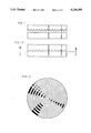
FIG. 1 is a cross-sectional view of a target and backing plate prior to assembly and bonding;
FIG. 2 is a cross-sectional view of a bonded target and backing plate assembly in accordance with the invention;
FIG. 3 is a cross-sectional view taken along the lines and arrows 3--3 of FIG. 2;
FIG. 4 is a top plan view of another embodiment of the invention illustrating a circular, concave face target/backing plate assembly; and
FIG. 5 is a sectional view taken along the lines and arrows 5--5 of FIG. 4.
Turning first to FIG. 1, there is shown target 2 and backing plate 10 prior to bonding. Target 2 includes upper face surface 4 which, in accordance with sputtering technique, will be bombarded with excited inert gas ions during sputtering, dislodging material from surface 4 for ejection therefrom and onto a substrate located proximate the anode (not shown). Together, target 2 and backing plate 10 are part of the cathode of the sputtering assembly.
Bottom surface 6 of the target is provided with a plurality of saw-tooth shaped grooves 8 which may be machined in the surface in accordance with well-known techniques. Bottom surface 6 is adapted for mating with top surface 12 of backing plate 10. Normally, the backing plate is composed of a high thermal conductivity metal, such as copper or aluminum. In most operations, a cooling medium (not shown) is circulated in heat exchange relation with bottom surface 14 of backing plate 10 to transfer heat from the target 2 that results from sputtering operation.
As per FIG. 2, the grooved surface 6 of target 2 is superposed on top of mating top surface of backing plate 12. The, under controlled atmosphere conditions, the so assembled target/backing plate structure is heated and pressed until the material from backing plate 10 substantially fills the grooves which define the saw-tooth pattern to effect bonding of the target and backing plate.
As to the controlled atmosphere, this is most preferably a vacuum but the bonding operation could also be conducted under an inert gas atmosphere or under reducing conditions such as under a nitrogen blanket. The important factor is that oxygen must be excluded from the bonding operation. Otherwise, component metal oxide films could form that would adversely affect bond strength and performance.
The target/backing plate assembly is to be heated either prior to or concurrently with the pressing step. In accordance with solid state bonding methods, these temperatures will be chosen so as to be just below the melting point of the lower melting component of the target-backing plate combination.
Preferably, the target/backing plate assembly is placed in a protective envelope, such as supplied by a stationary hard shell furnace or by encapsulating the assembly in a thin metal container. When the container approach is used, it can be evacuated through a tube or the like that is provided in the container. When a furnace is used, the atmosphere is controlled as stated supra., so that, preferably, a vacuum exists therein.
Pressure applied during the bonding operation may vary over a wide range. The pressure and time required for pressing are controlled so that a strong bond can be formed. Of primary importance is the fact that the grooved component should penetrate into the softer, non-grooved component so that the saw-toothed shaped grooves are substantially filled with this softer metal component. Pressure may vary from 2,000-15,000 psi depending on process conditions.
In accordance with the presently preferred method, a titanium target is diffusion bonded to an aluminum backing plate. A plurality of concentric grooves having a depth of 1/16" are machined in the bottom surface 6 of the titanium target. The target/backing plate assembly is positioned as shown in FIG. 2 and placed in a steel container that is then evacuated to vacuum condition. The assembly is heated to about 550°-625° C. (i.e., just below the melting point of the backing plate). The assembly is pressed at about 10,000 psi until the saw-tooth grooves in the titanium target are filled with aluminum. As another way of assessing the pressing step, the aluminum in the steel can is compressed approximately 1/8", about twice the height dimension of the grooves.
In addition to the preferred bonding method, the assembly could also be placed in a HIP (hot isostatic pressing) can, and HIPed at a temperature of about 600° C. or less under HIPing pressures of about 15,000 psi. This is not preferred however due to its expensive nature.
Another alternative approach is to place a preheated target/backing plate assembly in a vacuum chamber and then press the assembly in an open platen type press or the like until adequate coalescence of the interfaces in accordance with the parameters mentioned above occurs.
Turning now to FIG. 3, there is shown underneath side 6 of target 2. A plurality of concentric grooves 8 are provided which, as per the above, are machined into the surface prior to bonding. Although concentric grooves are shown and are preferred, other closed-looped configurations including triangles, squares, rectangles, and ovals may also be used. The point is that the grooves or loops should be closed so that any oxygen trapped in the metal surface will be impeded from migrating out of the surface during the sputtering operation. Such migration would contaminate the sputtering chamber and could lead to the formation of impurities on the sputter-coated substrate.
In addition to use in conjunction with titanium target/aluminum backing plate assemblies, the invention is applicable to a host of other target/backing plate compositions. For example, a molybdenum target/copper backing plate assembly can be solid state bonded in accordance with the invention. In this case, the bottom side of the molybdenum target is grooved and the assembly would be heated to just below the melting point of the copper or copper alloy. In all of the possible target/backing plate combinations, the harder component is provided with the grooved, interfacial surface, and the heat applied, as per solid state bonding techniques, is controlled to temperatures below the melting point of the lower melting component.
Other target/backing plate assemblies that can be effectively bonded in accordance with the invention include precious metal targets in combination with copper backing plates. The precious metals include Ru, Rh, Pd, Ag, Os, Ir, Pt and gold.
Although the preferred embodiment depicted in FIGS. 1-3 illustrates a circular, planar surface target 2, FIGS. 4 and 5 illustrate that the inventive techniques can also be used to provide a concave face 16 target over a corresponding backing structure. Again, a saw-toothed shaped grooved pattern is provided in the bottom side 6 of the target that is solid state bonded to surface 12 of the associated backing plate.
The invention provides improvement over the use of soft solder bonds in that it can be used over a wider range of sputtering power levels and target operating temperatures without fear of bond melt failures. Additionally, large targets can be bonded with less concern for shear failures along the bonded interface.
The bonds produced by this invention are less costly to develop or produce than by explosive bonding. In the case of HIP bonding, a number of target assemblies can be pressed simultaneously. In press bonding, several assemblies can be furnace heated at one time and each pressed in fairly rapid succession. The mechanical features of the bond interface are more regular and predictable than the "jetting"-type interface features produced in an explosive operation. The bonding operation by this invention reduces the amount of initial oversize condition and amount of post bonding stock removal in the machining operations.
Conventional diffusion bonding necessitates high quality surface cleaning and surface maintenance before and through the bonding operation. The components associated with this invention are less sensitive to surface films or contamination because of the significant degree of mechanical surface disruption occurring during pressure contacting of the components. This type of surface disruption reduces the time and temperature of pressing and, depending on the specific materials involved, yields a solid state bond with little if any interdiffusion of the components.
An important feature of this invention is the use of a closed, grooved or notedly irregular surface of one component which enhances bonding as a result of the disruption of the mating smooth-faced component. In addition, the resulting bond interface feature provides an enhancement of the resistance of the bonded assembly to shear caused by a difference in thermal expansion characteristics and the change in temperature from bonding level to ambient.
While the method described herein and the target/backing plate assemblies produced in accordance with the method have been described with certain specific forms and certain modifications thereof, it will be appreciated that a wide variety of other modifications can be made without departing from the scope and spirit of this invention as defined in the appended claims. It is also to be kept in mind that reference to a metal or metal component herein also includes reference to alloyed forms of the stated metal.
Claims (16)
1. In a method of preparing a bonded sputter target/backing plate assembly comprising a target composed of a first metal or alloy to be sputtered and an underlying backing plate member composed of a second metal or alloy, an improved method for joining said target and backing plate along mating surfaces thereof, comprising:
forming a plurality of grooves in one of said mating surfaces,
positioning said target and backing plate adjacent each other to form an assembly having an interface defined by said mating surfaces;
subjecting said assembly to a controlled atmosphere selected from the group consisting of a vacuum, inert, or reducing conditions;
heating said assembly; and
pressing said assembly so that said grooves are substantially filled with metal or alloy from the other of said mating surfaces.
2. Method as recited in claim 1 wherein said grooves comprise a plurality of closed loop configurations.
3. Method as recited in claim 2 wherein said grooves comprise a plurality of concentric circular grooves.
4. Method as recited in claim 1 wherein said controlled atmosphere is a vacuum.
5. Method as recited in claim 1 wherein said target comprises titanium or titanium alloy and said backing plate comprises aluminum or aluminum alloy.
6. Method as recited in claim 5 wherein said heating comprises heating said assembly to a temperature less than the melting point of said aluminum or aluminum alloy.
7. Method as recited in claim 6 wherein said heating comprises heating said assembly to about 550°-625° C.
8. Method as recited in claim 7 wherein said pressing comprises pressing said assembly at a pressure of about 2,000-15,000 psi.
9. Method as recited in claim 1 wherein said target comprises molybdenum or molybdenum alloy and said backing plate comprises copper or copper alloy.
10. Method as recited in claim 9 wherein said heating comprises heating said assembly to a temperature less than the melting point of said copper or copper alloy.
11. Method as recited in claim 1 wherein said target comprises a precious metal or precious metal alloy, said precious metal being chosen from the group consisting of Ru, Rh, Pd, Ag, Os, Ir, Pt and Au.
12. Method as recited in claim 11 wherein said backing plate comprises copper or copper alloy.
13. Assembly made in accordance with claim 1.
14. Assembly made in accordance with claim 5.
15. Assembly made in accordance with claim 9.
16. Assembly made in accordance with claim 11.
Priority Applications (6)
| Application Number | Priority Date | Filing Date | Title |
|---|---|---|---|
| US07/853,095 US5230459A (en) | 1992-03-18 | 1992-03-18 | Method of bonding a sputter target-backing plate assembly assemblies produced thereby |
| PCT/US1993/002415 WO1993019220A1 (en) | 1992-03-18 | 1993-03-17 | Method of bonding a sputter target-backing plate assembly and assemblies produced thereby |
| KR1019940701197A KR100274488B1 (en) | 1992-03-18 | 1993-03-17 | Method of bonding a sputter target backing plate assembly and assemblies produced thereby |
| JP5516689A JPH07504945A (en) | 1992-03-18 | 1993-03-17 | Method for joining sputter target backing plate assemblies and assemblies produced thereby |
| DE69318975T DE69318975T2 (en) | 1992-03-18 | 1993-03-17 | METHOD FOR CONNECTING A SPUTTER TARGET SUPPORT PLATE UNIT |
| EP93908369A EP0630423B1 (en) | 1992-03-18 | 1993-03-17 | Method of bonding a sputter target-backing plate assembly |
Applications Claiming Priority (1)
| Application Number | Priority Date | Filing Date | Title |
|---|---|---|---|
| US07/853,095 US5230459A (en) | 1992-03-18 | 1992-03-18 | Method of bonding a sputter target-backing plate assembly assemblies produced thereby |
Publications (1)
| Publication Number | Publication Date |
|---|---|
| US5230459A true US5230459A (en) | 1993-07-27 |
Family
ID=25315033
Family Applications (1)
| Application Number | Title | Priority Date | Filing Date |
|---|---|---|---|
| US07/853,095 Expired - Lifetime US5230459A (en) | 1992-03-18 | 1992-03-18 | Method of bonding a sputter target-backing plate assembly assemblies produced thereby |
Country Status (6)
| Country | Link |
|---|---|
| US (1) | US5230459A (en) |
| EP (1) | EP0630423B1 (en) |
| JP (1) | JPH07504945A (en) |
| KR (1) | KR100274488B1 (en) |
| DE (1) | DE69318975T2 (en) |
| WO (1) | WO1993019220A1 (en) |
Cited By (68)
| Publication number | Priority date | Publication date | Assignee | Title |
|---|---|---|---|---|
| US5342496A (en) * | 1993-05-18 | 1994-08-30 | Tosoh Smd, Inc. | Method of welding sputtering target/backing plate assemblies |
| US5397050A (en) * | 1993-10-27 | 1995-03-14 | Tosoh Smd, Inc. | Method of bonding tungsten titanium sputter targets to titanium plates and target assemblies produced thereby |
| US5428882A (en) * | 1993-04-05 | 1995-07-04 | The Regents Of The University Of California | Process for the fabrication of aluminum metallized pyrolytic graphite sputtering targets |
| EP0761372A1 (en) * | 1995-08-07 | 1997-03-12 | Applied Materials, Inc. | Preparation and bonding of workpieces to form sputtering targets and other assemblies |
| US5693203A (en) * | 1992-09-29 | 1997-12-02 | Japan Energy Corporation | Sputtering target assembly having solid-phase bonded interface |
| US5803342A (en) * | 1996-12-26 | 1998-09-08 | Johnson Matthey Electronics, Inc. | Method of making high purity copper sputtering targets |
| US5836506A (en) * | 1995-04-21 | 1998-11-17 | Sony Corporation | Sputter target/backing plate assembly and method of making same |
| US5847725A (en) * | 1997-07-28 | 1998-12-08 | Hewlett-Packard Company | Expansion relief for orifice plate of thermal ink jet print head |
| US5857611A (en) * | 1995-08-16 | 1999-01-12 | Sony Corporation | Sputter target/backing plate assembly and method of making same |
| US5863398A (en) * | 1996-10-11 | 1999-01-26 | Johnson Matthey Electonics, Inc. | Hot pressed and sintered sputtering target assemblies and method for making same |
| US5963778A (en) * | 1997-02-13 | 1999-10-05 | Tosoh Smd, Inc. | Method for producing near net shape planar sputtering targets and an intermediate therefor |
| WO2000015863A1 (en) * | 1998-09-11 | 2000-03-23 | Tosoh Smd, Inc. | Low temperature sputter target bonding method and target assemblies produced thereby |
| US6071389A (en) * | 1998-08-21 | 2000-06-06 | Tosoh Smd, Inc. | Diffusion bonded sputter target assembly and method of making |
| US6073830A (en) * | 1995-04-21 | 2000-06-13 | Praxair S.T. Technology, Inc. | Sputter target/backing plate assembly and method of making same |
| US6164519A (en) * | 1999-07-08 | 2000-12-26 | Praxair S.T. Technology, Inc. | Method of bonding a sputtering target to a backing plate |
| US6183686B1 (en) | 1998-08-04 | 2001-02-06 | Tosoh Smd, Inc. | Sputter target assembly having a metal-matrix-composite backing plate and methods of making same |
| US6274015B1 (en) | 1996-12-13 | 2001-08-14 | Honeywell International, Inc. | Diffusion bonded sputtering target assembly with precipitation hardened backing plate and method of making same |
| US20020028538A1 (en) * | 2000-01-20 | 2002-03-07 | Chris Parfeniuk | Physical Vapor Deposition Target Constructions |
| WO2002022300A1 (en) * | 2000-09-11 | 2002-03-21 | Tosoh Smd, Inc. | Method of manufacturing sputter targets with internal cooling channels |
| US6371357B1 (en) * | 1998-01-12 | 2002-04-16 | Furakawa Electric Co., Inc. | Highly gas tight chamber and method of manufacturing same |
| WO2002049785A1 (en) * | 2000-12-18 | 2002-06-27 | Tosoh Smd, Inc. | Low temperature sputter target/backing plate joining technique and assemblies made thereby |
| US6419806B1 (en) | 1998-12-03 | 2002-07-16 | Tosoh Smd, Inc. | Insert target assembly and method of making same |
| US6451185B2 (en) | 1998-08-12 | 2002-09-17 | Honeywell International Inc. | Diffusion bonded sputtering target assembly with precipitation hardened backing plate and method of making same |
| WO2002099157A1 (en) * | 2001-05-30 | 2002-12-12 | Praxair S.T. Technology, Inc. | Recessed sputter target |
| WO2003000950A1 (en) * | 2001-02-20 | 2003-01-03 | Honeywell International Inc. | Topologically tailored sputtering targets |
| US6521108B1 (en) | 1998-12-29 | 2003-02-18 | Tosoh Smd, Inc. | Diffusion bonded sputter target assembly and method of making same |
| US6527368B1 (en) | 2002-04-30 | 2003-03-04 | Hewlett-Packard Company | Layer with discontinuity over fluid slot |
| US6555250B2 (en) | 1997-03-19 | 2003-04-29 | Honeywell International Inc. | Ni-plated target diffusion bonded to a backing plate and method of making same |
| US6579431B1 (en) * | 1998-01-14 | 2003-06-17 | Tosoh Smd, Inc. | Diffusion bonding of high purity metals and metal alloys to aluminum backing plates using nickel or nickel alloy interlayers |
| US6619537B1 (en) | 2000-06-12 | 2003-09-16 | Tosoh Smd, Inc. | Diffusion bonding of copper sputtering targets to backing plates using nickel alloy interlayers |
| US20040020769A1 (en) * | 2000-08-17 | 2004-02-05 | Ivannov Eugene Y | High purity sputter targets with target end-of-life indication and method of manufacture |
| US6698647B1 (en) * | 2000-03-10 | 2004-03-02 | Honeywell International Inc. | Aluminum-comprising target/backing plate structures |
| US6711803B1 (en) * | 1998-12-25 | 2004-03-30 | Takashima Corporation | Method of joining steel products, method of processing junction surfaces of steel products, and reinforcing member |
| US20040065546A1 (en) * | 2002-10-04 | 2004-04-08 | Michaluk Christopher A. | Method to recover spent components of a sputter target |
| US20040079634A1 (en) * | 2002-10-21 | 2004-04-29 | Wickersham Charles E. | Method of forming a sputtering target assembly and assembly made therefrom |
| US6749103B1 (en) * | 1998-09-11 | 2004-06-15 | Tosoh Smd, Inc. | Low temperature sputter target bonding method and target assemblies produced thereby |
| US20040129560A1 (en) * | 2002-10-01 | 2004-07-08 | Wickersham Charles E. | Method of bonding sputtering target materials |
| US6774339B1 (en) * | 1999-11-09 | 2004-08-10 | Tosoh Smd, Inc. | Hermetic sealing of target/backing plate assemblies using electron beam melted indium or tin |
| US20040200419A1 (en) * | 2003-04-11 | 2004-10-14 | Justin Mauck | Explosion welded design for cooling components |
| US20040262157A1 (en) * | 2003-02-25 | 2004-12-30 | Ford Robert B. | Method of forming sputtering target assembly and assemblies made therefrom |
| US20050061857A1 (en) * | 2003-09-24 | 2005-03-24 | Hunt Thomas J. | Method for bonding a sputter target to a backing plate and the assembly thereof |
| US20050067469A1 (en) * | 2003-09-26 | 2005-03-31 | Facey Joseph C. | Method for centering a sputter target onto a backing plate and the assembly thereof |
| US20050178818A1 (en) * | 1998-12-25 | 2005-08-18 | Kiyokazu Kobayashi | Method of joining steel members, method of processing joined surface of steel member and reinforcing member |
| US20050236270A1 (en) * | 2004-04-23 | 2005-10-27 | Heraeus, Inc. | Controlled cooling of sputter targets |
| KR100536580B1 (en) * | 1998-09-23 | 2006-03-09 | 삼성전자주식회사 | Target Chiller in Sputtering System |
| US20060065517A1 (en) * | 2002-06-14 | 2006-03-30 | Tosoh Smd, Inc. | Target and method of diffusion bonding target to backing plate |
| US20070056845A1 (en) * | 2005-09-13 | 2007-03-15 | Applied Materials, Inc. | Multiple zone sputtering target created through conductive and insulation bonding |
| US20070084719A1 (en) * | 2005-09-28 | 2007-04-19 | Wickersham Charles E Jr | Inertial bonding method of forming a sputtering target assembly and assembly made therefrom |
| US20080149477A1 (en) * | 2006-12-22 | 2008-06-26 | Chi-Fung Lo | Method for consolidating and diffusion-bonding powder metallurgy sputtering target |
| US20080174007A1 (en) * | 2003-03-31 | 2008-07-24 | Intel Corporation | Heat sink with preattached thermal interface material and method of making same |
| US20080236738A1 (en) * | 2007-03-30 | 2008-10-02 | Chi-Fung Lo | Bonded sputtering target and methods of manufacture |
| US20080265047A1 (en) * | 2007-04-25 | 2008-10-30 | Scott Powers | Railway tie of non-homogeneous cross section useful in environments deleterious to timber |
| US7588668B2 (en) | 2005-09-13 | 2009-09-15 | Applied Materials, Inc. | Thermally conductive dielectric bonding of sputtering targets using diamond powder filler or thermally conductive ceramic fillers |
| WO2012170622A1 (en) * | 2011-06-10 | 2012-12-13 | Praxair Technology, Inc. | Rotary sputter target assembly |
| US20130089709A1 (en) * | 2011-10-06 | 2013-04-11 | Hon Hai Precision Industry Co., Ltd. | Three-dimensional nano-structure array |
| US8430334B1 (en) | 2007-04-25 | 2013-04-30 | Jonathan Jaffe | Railroad tie of non-homogeneous cross section useful in environments deleterious to timber |
| WO2013070679A1 (en) * | 2011-11-08 | 2013-05-16 | Tosoh Smd, Inc. | Silicon sputtering target with special surface treatment and good particle performance and methods of making the same |
| US20130161188A1 (en) * | 2010-06-18 | 2013-06-27 | Robert Linsbod | Method for Bonding Components of a Sputtering Target, a Bonded Assembly of Sputtering Target Components and the Use Thereof |
| US20150155143A1 (en) * | 2010-03-12 | 2015-06-04 | Applied Materials, Inc. | Apparatus And Method For Improved Darkspace Gap Design In RF Sputtering Chamber |
| CN104741776A (en) * | 2013-12-31 | 2015-07-01 | 宁波江丰电子材料股份有限公司 | Welding method of target component |
| CN105048240A (en) * | 2015-06-11 | 2015-11-11 | 上海交通大学 | Rotatable pressure-applying connection method for aluminum-copper structure |
| CN106163714A (en) * | 2014-03-24 | 2016-11-23 | 瑟莫康柏克特公司 | The method manufacturing the closed loop of line of cut |
| CN106271033A (en) * | 2016-08-28 | 2017-01-04 | 中航力源液压股份有限公司 | A kind of tin bronze and the diffusion welding method of steel welding construction |
| US9581875B2 (en) | 2005-02-23 | 2017-02-28 | Sage Electrochromics, Inc. | Electrochromic devices and methods |
| CN108367537A (en) * | 2015-07-13 | 2018-08-03 | 雅宝公司 | The method that solid-state lithium low pressure cold is bound to metal base |
| US10138544B2 (en) | 2011-06-27 | 2018-11-27 | Soleras, LTd. | Sputtering target |
| CN110539067A (en) * | 2019-09-16 | 2019-12-06 | 宁波江丰电子材料股份有限公司 | Diffusion welding method for high-purity copper target |
| CN112935511A (en) * | 2021-03-26 | 2021-06-11 | 宁波江丰电子材料股份有限公司 | Diffusion welding method for cobalt target and copper-zinc alloy back plate |
Families Citing this family (7)
| Publication number | Priority date | Publication date | Assignee | Title |
|---|---|---|---|---|
| KR100620213B1 (en) * | 2005-05-31 | 2006-09-06 | 어플라이드 사이언스(주) | Solder bonding method for sputtering target |
| US20080145688A1 (en) | 2006-12-13 | 2008-06-19 | H.C. Starck Inc. | Method of joining tantalum clade steel structures |
| US8197894B2 (en) | 2007-05-04 | 2012-06-12 | H.C. Starck Gmbh | Methods of forming sputtering targets |
| US8246903B2 (en) | 2008-09-09 | 2012-08-21 | H.C. Starck Inc. | Dynamic dehydriding of refractory metal powders |
| WO2013049274A2 (en) | 2011-09-29 | 2013-04-04 | H.C. Starck, Inc. | Large-area sputtering targets and methods of manufacturing large-area sputtering targets |
| CN110788471A (en) * | 2019-11-28 | 2020-02-14 | 宁波江丰电子材料股份有限公司 | Metal welding method |
| CN111843161B (en) * | 2020-07-17 | 2022-02-08 | 宁波江丰电子材料股份有限公司 | WTi target and copper back plate welding method |
Citations (7)
| Publication number | Priority date | Publication date | Assignee | Title |
|---|---|---|---|---|
| US4468313A (en) * | 1981-03-03 | 1984-08-28 | Tokyo Shibaura Denki Kabushiki Kaisha | Sputtering target |
| US4610774A (en) * | 1984-11-14 | 1986-09-09 | Hitachi, Ltd. | Target for sputtering |
| US4752335A (en) * | 1986-04-30 | 1988-06-21 | Schwarzkopf Development Corporation | Process for the manufacture of a target for cathodic sputtering |
| US4820397A (en) * | 1988-04-04 | 1989-04-11 | Tosoh Smd, Inc. | Quick change sputter target assembly |
| US4826584A (en) * | 1986-04-17 | 1989-05-02 | Dos Santos Pereiro Ribeiro Car | Magnetron sputtering cathode |
| US5009765A (en) * | 1990-05-17 | 1991-04-23 | Tosoh Smd, Inc. | Sputter target design |
| US5066381A (en) * | 1988-04-15 | 1991-11-19 | Sharp Kabushiki Kaisha | Target unit |
Family Cites Families (4)
| Publication number | Priority date | Publication date | Assignee | Title |
|---|---|---|---|---|
| EP0276962A1 (en) * | 1987-01-27 | 1988-08-03 | Machine Technology Inc. | Cooling device for a sputter target and source |
| JPS63270459A (en) * | 1987-04-24 | 1988-11-08 | Matsushita Electric Ind Co Ltd | Bonding method for sputtering target |
| JPH028364A (en) * | 1988-06-24 | 1990-01-11 | Matsushita Electric Ind Co Ltd | Sputtering target and its production |
| DE3839775C2 (en) * | 1988-11-25 | 1998-12-24 | Vaw Ver Aluminium Werke Ag | Cathode sputtering target and process for its manufacture |
-
1992
- 1992-03-18 US US07/853,095 patent/US5230459A/en not_active Expired - Lifetime
-
1993
- 1993-03-17 DE DE69318975T patent/DE69318975T2/en not_active Expired - Fee Related
- 1993-03-17 WO PCT/US1993/002415 patent/WO1993019220A1/en active IP Right Grant
- 1993-03-17 KR KR1019940701197A patent/KR100274488B1/en not_active IP Right Cessation
- 1993-03-17 JP JP5516689A patent/JPH07504945A/en active Pending
- 1993-03-17 EP EP93908369A patent/EP0630423B1/en not_active Expired - Lifetime
Patent Citations (7)
| Publication number | Priority date | Publication date | Assignee | Title |
|---|---|---|---|---|
| US4468313A (en) * | 1981-03-03 | 1984-08-28 | Tokyo Shibaura Denki Kabushiki Kaisha | Sputtering target |
| US4610774A (en) * | 1984-11-14 | 1986-09-09 | Hitachi, Ltd. | Target for sputtering |
| US4826584A (en) * | 1986-04-17 | 1989-05-02 | Dos Santos Pereiro Ribeiro Car | Magnetron sputtering cathode |
| US4752335A (en) * | 1986-04-30 | 1988-06-21 | Schwarzkopf Development Corporation | Process for the manufacture of a target for cathodic sputtering |
| US4820397A (en) * | 1988-04-04 | 1989-04-11 | Tosoh Smd, Inc. | Quick change sputter target assembly |
| US5066381A (en) * | 1988-04-15 | 1991-11-19 | Sharp Kabushiki Kaisha | Target unit |
| US5009765A (en) * | 1990-05-17 | 1991-04-23 | Tosoh Smd, Inc. | Sputter target design |
Cited By (113)
| Publication number | Priority date | Publication date | Assignee | Title |
|---|---|---|---|---|
| US5693203A (en) * | 1992-09-29 | 1997-12-02 | Japan Energy Corporation | Sputtering target assembly having solid-phase bonded interface |
| US5428882A (en) * | 1993-04-05 | 1995-07-04 | The Regents Of The University Of California | Process for the fabrication of aluminum metallized pyrolytic graphite sputtering targets |
| US5342496A (en) * | 1993-05-18 | 1994-08-30 | Tosoh Smd, Inc. | Method of welding sputtering target/backing plate assemblies |
| US5397050A (en) * | 1993-10-27 | 1995-03-14 | Tosoh Smd, Inc. | Method of bonding tungsten titanium sputter targets to titanium plates and target assemblies produced thereby |
| US6073830A (en) * | 1995-04-21 | 2000-06-13 | Praxair S.T. Technology, Inc. | Sputter target/backing plate assembly and method of making same |
| US5836506A (en) * | 1995-04-21 | 1998-11-17 | Sony Corporation | Sputter target/backing plate assembly and method of making same |
| EP0761372A1 (en) * | 1995-08-07 | 1997-03-12 | Applied Materials, Inc. | Preparation and bonding of workpieces to form sputtering targets and other assemblies |
| US5799860A (en) * | 1995-08-07 | 1998-09-01 | Applied Materials, Inc. | Preparation and bonding of workpieces to form sputtering targets and other assemblies |
| US5857611A (en) * | 1995-08-16 | 1999-01-12 | Sony Corporation | Sputter target/backing plate assembly and method of making same |
| US6183613B1 (en) | 1995-08-16 | 2001-02-06 | Praxair S.T. Technology, Inc. | Sputter target/backing plate assembly and method of making same |
| US5863398A (en) * | 1996-10-11 | 1999-01-26 | Johnson Matthey Electonics, Inc. | Hot pressed and sintered sputtering target assemblies and method for making same |
| US6274015B1 (en) | 1996-12-13 | 2001-08-14 | Honeywell International, Inc. | Diffusion bonded sputtering target assembly with precipitation hardened backing plate and method of making same |
| US5803342A (en) * | 1996-12-26 | 1998-09-08 | Johnson Matthey Electronics, Inc. | Method of making high purity copper sputtering targets |
| US5963778A (en) * | 1997-02-13 | 1999-10-05 | Tosoh Smd, Inc. | Method for producing near net shape planar sputtering targets and an intermediate therefor |
| US6555250B2 (en) | 1997-03-19 | 2003-04-29 | Honeywell International Inc. | Ni-plated target diffusion bonded to a backing plate and method of making same |
| US6360439B1 (en) | 1997-07-28 | 2002-03-26 | Hewlett-Packard Company | Method of manufacturing an orifice plate having a plurality of closed slits |
| US5847725A (en) * | 1997-07-28 | 1998-12-08 | Hewlett-Packard Company | Expansion relief for orifice plate of thermal ink jet print head |
| US6552311B2 (en) * | 1998-01-12 | 2003-04-22 | The Furukawa Electric Co., Ltd. | Highly gas tight chamber and method of manufacturing same |
| US6371357B1 (en) * | 1998-01-12 | 2002-04-16 | Furakawa Electric Co., Inc. | Highly gas tight chamber and method of manufacturing same |
| US6579431B1 (en) * | 1998-01-14 | 2003-06-17 | Tosoh Smd, Inc. | Diffusion bonding of high purity metals and metal alloys to aluminum backing plates using nickel or nickel alloy interlayers |
| US6183686B1 (en) | 1998-08-04 | 2001-02-06 | Tosoh Smd, Inc. | Sputter target assembly having a metal-matrix-composite backing plate and methods of making same |
| US6451185B2 (en) | 1998-08-12 | 2002-09-17 | Honeywell International Inc. | Diffusion bonded sputtering target assembly with precipitation hardened backing plate and method of making same |
| US6071389A (en) * | 1998-08-21 | 2000-06-06 | Tosoh Smd, Inc. | Diffusion bonded sputter target assembly and method of making |
| EP1115899A4 (en) * | 1998-09-11 | 2004-09-22 | Tosoh Smd Inc | Low temperature sputter target bonding method and target assemblies produced thereby |
| US6749103B1 (en) * | 1998-09-11 | 2004-06-15 | Tosoh Smd, Inc. | Low temperature sputter target bonding method and target assemblies produced thereby |
| EP1115899A1 (en) * | 1998-09-11 | 2001-07-18 | Tosoh Smd, Inc. | Low temperature sputter target bonding method and target assemblies produced thereby |
| WO2000015863A1 (en) * | 1998-09-11 | 2000-03-23 | Tosoh Smd, Inc. | Low temperature sputter target bonding method and target assemblies produced thereby |
| KR100536580B1 (en) * | 1998-09-23 | 2006-03-09 | 삼성전자주식회사 | Target Chiller in Sputtering System |
| US6419806B1 (en) | 1998-12-03 | 2002-07-16 | Tosoh Smd, Inc. | Insert target assembly and method of making same |
| US20050178818A1 (en) * | 1998-12-25 | 2005-08-18 | Kiyokazu Kobayashi | Method of joining steel members, method of processing joined surface of steel member and reinforcing member |
| US6711803B1 (en) * | 1998-12-25 | 2004-03-30 | Takashima Corporation | Method of joining steel products, method of processing junction surfaces of steel products, and reinforcing member |
| US6521108B1 (en) | 1998-12-29 | 2003-02-18 | Tosoh Smd, Inc. | Diffusion bonded sputter target assembly and method of making same |
| US6164519A (en) * | 1999-07-08 | 2000-12-26 | Praxair S.T. Technology, Inc. | Method of bonding a sputtering target to a backing plate |
| US6774339B1 (en) * | 1999-11-09 | 2004-08-10 | Tosoh Smd, Inc. | Hermetic sealing of target/backing plate assemblies using electron beam melted indium or tin |
| US6797362B2 (en) | 2000-01-20 | 2004-09-28 | Honeywell International Inc. | Physical vapor deposition target constructions |
| US6780794B2 (en) | 2000-01-20 | 2004-08-24 | Honeywell International Inc. | Methods of bonding physical vapor deposition target materials to backing plate materials |
| US20020028538A1 (en) * | 2000-01-20 | 2002-03-07 | Chris Parfeniuk | Physical Vapor Deposition Target Constructions |
| US6698647B1 (en) * | 2000-03-10 | 2004-03-02 | Honeywell International Inc. | Aluminum-comprising target/backing plate structures |
| US6840431B1 (en) * | 2000-03-10 | 2005-01-11 | Honeywell International Inc. | Methods of bonding two aluminum-comprising masses to one another |
| US6619537B1 (en) | 2000-06-12 | 2003-09-16 | Tosoh Smd, Inc. | Diffusion bonding of copper sputtering targets to backing plates using nickel alloy interlayers |
| US7063773B2 (en) | 2000-08-17 | 2006-06-20 | Tosoh Smd, Inc. | High purity sputter targets with target end-of-life indication and method of manufacture |
| US20040020769A1 (en) * | 2000-08-17 | 2004-02-05 | Ivannov Eugene Y | High purity sputter targets with target end-of-life indication and method of manufacture |
| US6840427B2 (en) * | 2000-09-11 | 2005-01-11 | Tosoh Smd, Inc. | Method of manufacturing sputter targets with internal cooling channels |
| US20040056070A1 (en) * | 2000-09-11 | 2004-03-25 | Ivanov Eugene Y | Method of manufacturing sputter targets with internal cooling channels |
| US6955852B2 (en) | 2000-09-11 | 2005-10-18 | Tosoh Smd, Inc. | Method of manufacturing sputter targets with internal cooling channels |
| US20050092604A1 (en) * | 2000-09-11 | 2005-05-05 | Tosoh Smd, Inc. | Method of manufacturing sputter targets with internal cooling channels |
| WO2002022300A1 (en) * | 2000-09-11 | 2002-03-21 | Tosoh Smd, Inc. | Method of manufacturing sputter targets with internal cooling channels |
| KR100817742B1 (en) | 2000-12-18 | 2008-03-31 | 토소우 에스엠디, 인크 | Low temperature sputter target/backing plate joining technique and assemblies made thereby |
| US20040113364A1 (en) * | 2000-12-18 | 2004-06-17 | Eugene Ivanov | Low temperature sputter target/backing plate joining technique and assemblies made thereby |
| US7146703B2 (en) | 2000-12-18 | 2006-12-12 | Tosoh Smd | Low temperature sputter target/backing plate method and assembly |
| WO2002049785A1 (en) * | 2000-12-18 | 2002-06-27 | Tosoh Smd, Inc. | Low temperature sputter target/backing plate joining technique and assemblies made thereby |
| WO2003000950A1 (en) * | 2001-02-20 | 2003-01-03 | Honeywell International Inc. | Topologically tailored sputtering targets |
| KR100885770B1 (en) * | 2001-05-30 | 2009-02-26 | 프랙스에어 에스.티. 테크놀로지, 인코포레이티드 | Sputter target assembly and method of manufacturing the same |
| WO2002099157A1 (en) * | 2001-05-30 | 2002-12-12 | Praxair S.T. Technology, Inc. | Recessed sputter target |
| US6527368B1 (en) | 2002-04-30 | 2003-03-04 | Hewlett-Packard Company | Layer with discontinuity over fluid slot |
| US20030202052A1 (en) * | 2002-04-30 | 2003-10-30 | Manish Giri | Layer with discontinuity over fluid slot |
| US20060125885A1 (en) * | 2002-04-30 | 2006-06-15 | Manish Giri | Layer with discontinuity over fluid slot |
| US7024768B2 (en) | 2002-04-30 | 2006-04-11 | Hewlett-Packard Development Company, L.P. | Fluid ejection device having a layer with a discontinuity |
| US20060065517A1 (en) * | 2002-06-14 | 2006-03-30 | Tosoh Smd, Inc. | Target and method of diffusion bonding target to backing plate |
| US6848608B2 (en) | 2002-10-01 | 2005-02-01 | Cabot Corporation | Method of bonding sputtering target materials |
| US20040129560A1 (en) * | 2002-10-01 | 2004-07-08 | Wickersham Charles E. | Method of bonding sputtering target materials |
| US20040065546A1 (en) * | 2002-10-04 | 2004-04-08 | Michaluk Christopher A. | Method to recover spent components of a sputter target |
| US20040079634A1 (en) * | 2002-10-21 | 2004-04-29 | Wickersham Charles E. | Method of forming a sputtering target assembly and assembly made therefrom |
| US7467741B2 (en) | 2002-10-21 | 2008-12-23 | Cabot Corporation | Method of forming a sputtering target assembly and assembly made therefrom |
| US20040262157A1 (en) * | 2003-02-25 | 2004-12-30 | Ford Robert B. | Method of forming sputtering target assembly and assemblies made therefrom |
| US20080174007A1 (en) * | 2003-03-31 | 2008-07-24 | Intel Corporation | Heat sink with preattached thermal interface material and method of making same |
| US7821126B2 (en) * | 2003-03-31 | 2010-10-26 | Intel Corporation | Heat sink with preattached thermal interface material and method of making same |
| US20040200419A1 (en) * | 2003-04-11 | 2004-10-14 | Justin Mauck | Explosion welded design for cooling components |
| US6953143B2 (en) * | 2003-04-11 | 2005-10-11 | Advanced Energy Industries, Inc. | Explosion welded design for cooling components |
| US20050061857A1 (en) * | 2003-09-24 | 2005-03-24 | Hunt Thomas J. | Method for bonding a sputter target to a backing plate and the assembly thereof |
| US20080271997A1 (en) * | 2003-09-26 | 2008-11-06 | Facey Joseph C | Sputter target and backing plate assembly |
| US7431195B2 (en) | 2003-09-26 | 2008-10-07 | Praxair S.T. Technology, Inc. | Method for centering a sputter target onto a backing plate and the assembly thereof |
| US7891537B2 (en) | 2003-09-26 | 2011-02-22 | Praxair S. T. Technology, Inc. | Sputter target and backing plate assembly |
| US20100187098A1 (en) * | 2003-09-26 | 2010-07-29 | Facey Joseph C | Sputter target and backing plate assembly |
| US20050067469A1 (en) * | 2003-09-26 | 2005-03-31 | Facey Joseph C. | Method for centering a sputter target onto a backing plate and the assembly thereof |
| US7721939B2 (en) | 2003-09-26 | 2010-05-25 | Praxair S. T. Technology, Inc. | Sputter target and backing plate assembly |
| US20050236270A1 (en) * | 2004-04-23 | 2005-10-27 | Heraeus, Inc. | Controlled cooling of sputter targets |
| US9581875B2 (en) | 2005-02-23 | 2017-02-28 | Sage Electrochromics, Inc. | Electrochromic devices and methods |
| US10061174B2 (en) | 2005-02-23 | 2018-08-28 | Sage Electrochromics, Inc. | Electrochromic devices and methods |
| US11567383B2 (en) | 2005-02-23 | 2023-01-31 | Sage Electrochromics, Inc. | Electrochromic devices and methods |
| US20070056845A1 (en) * | 2005-09-13 | 2007-03-15 | Applied Materials, Inc. | Multiple zone sputtering target created through conductive and insulation bonding |
| US7588668B2 (en) | 2005-09-13 | 2009-09-15 | Applied Materials, Inc. | Thermally conductive dielectric bonding of sputtering targets using diamond powder filler or thermally conductive ceramic fillers |
| US20070084719A1 (en) * | 2005-09-28 | 2007-04-19 | Wickersham Charles E Jr | Inertial bonding method of forming a sputtering target assembly and assembly made therefrom |
| US20080149477A1 (en) * | 2006-12-22 | 2008-06-26 | Chi-Fung Lo | Method for consolidating and diffusion-bonding powder metallurgy sputtering target |
| US8206646B2 (en) | 2006-12-22 | 2012-06-26 | Praxair Tecnology, Inc. | Method for consolidating and diffusion-bonding powder metallurgy sputtering target |
| US20080236738A1 (en) * | 2007-03-30 | 2008-10-02 | Chi-Fung Lo | Bonded sputtering target and methods of manufacture |
| US20080265047A1 (en) * | 2007-04-25 | 2008-10-30 | Scott Powers | Railway tie of non-homogeneous cross section useful in environments deleterious to timber |
| US7942342B2 (en) * | 2007-04-25 | 2011-05-17 | Scott Powers | Railway tie of non-homogeneous cross section useful in environments deleterious to timber |
| US8430334B1 (en) | 2007-04-25 | 2013-04-30 | Jonathan Jaffe | Railroad tie of non-homogeneous cross section useful in environments deleterious to timber |
| US20150155143A1 (en) * | 2010-03-12 | 2015-06-04 | Applied Materials, Inc. | Apparatus And Method For Improved Darkspace Gap Design In RF Sputtering Chamber |
| US9373485B2 (en) * | 2010-03-12 | 2016-06-21 | Applied Materials, Inc. | Apparatus and method for improved darkspace gap design in RF sputtering chamber |
| US20130161188A1 (en) * | 2010-06-18 | 2013-06-27 | Robert Linsbod | Method for Bonding Components of a Sputtering Target, a Bonded Assembly of Sputtering Target Components and the Use Thereof |
| US20130140173A1 (en) * | 2011-06-10 | 2013-06-06 | Séverin Stéphane Gérard Tierce | Rotary sputter target assembly |
| WO2012170622A1 (en) * | 2011-06-10 | 2012-12-13 | Praxair Technology, Inc. | Rotary sputter target assembly |
| US10138544B2 (en) | 2011-06-27 | 2018-11-27 | Soleras, LTd. | Sputtering target |
| US20130089709A1 (en) * | 2011-10-06 | 2013-04-11 | Hon Hai Precision Industry Co., Ltd. | Three-dimensional nano-structure array |
| US9556018B2 (en) * | 2011-10-06 | 2017-01-31 | Tsinghua University | Three-dimensional nano-structure array |
| WO2013070679A1 (en) * | 2011-11-08 | 2013-05-16 | Tosoh Smd, Inc. | Silicon sputtering target with special surface treatment and good particle performance and methods of making the same |
| US9566618B2 (en) | 2011-11-08 | 2017-02-14 | Tosoh Smd, Inc. | Silicon sputtering target with special surface treatment and good particle performance and methods of making the same |
| CN104741776A (en) * | 2013-12-31 | 2015-07-01 | 宁波江丰电子材料股份有限公司 | Welding method of target component |
| CN104741776B (en) * | 2013-12-31 | 2016-07-06 | 宁波江丰电子材料股份有限公司 | The welding method of target material assembly |
| CN106163714B (en) * | 2014-03-24 | 2018-12-21 | 瑟莫康柏克特公司 | Manufacture the method for the closed loop of cutting line and the closed loop of cutting line |
| CN106163714A (en) * | 2014-03-24 | 2016-11-23 | 瑟莫康柏克特公司 | The method manufacturing the closed loop of line of cut |
| CN105048240B (en) * | 2015-06-11 | 2017-05-24 | 上海交通大学 | Rotatable pressure-applying connection method for aluminum-copper structure |
| CN105048240A (en) * | 2015-06-11 | 2015-11-11 | 上海交通大学 | Rotatable pressure-applying connection method for aluminum-copper structure |
| CN108367537A (en) * | 2015-07-13 | 2018-08-03 | 雅宝公司 | The method that solid-state lithium low pressure cold is bound to metal base |
| CN108367537B (en) * | 2015-07-13 | 2021-05-07 | 雅宝公司 | Method for low pressure cold bonding of solid lithium to metal substrates |
| US11001921B2 (en) * | 2015-07-13 | 2021-05-11 | Albemarle Corporation | Processes for low pressure, cold bonding of solid lithium to metal substrates |
| CN106271033A (en) * | 2016-08-28 | 2017-01-04 | 中航力源液压股份有限公司 | A kind of tin bronze and the diffusion welding method of steel welding construction |
| CN106271033B (en) * | 2016-08-28 | 2019-01-08 | 中航力源液压股份有限公司 | A kind of diffusion welding method of tin bronze and steel welding construction |
| CN110539067A (en) * | 2019-09-16 | 2019-12-06 | 宁波江丰电子材料股份有限公司 | Diffusion welding method for high-purity copper target |
| CN110539067B (en) * | 2019-09-16 | 2021-12-07 | 宁波江丰电子材料股份有限公司 | Diffusion welding method for high-purity copper target |
| CN112935511A (en) * | 2021-03-26 | 2021-06-11 | 宁波江丰电子材料股份有限公司 | Diffusion welding method for cobalt target and copper-zinc alloy back plate |
Also Published As
| Publication number | Publication date |
|---|---|
| EP0630423B1 (en) | 1998-06-03 |
| DE69318975D1 (en) | 1998-07-09 |
| JPH07504945A (en) | 1995-06-01 |
| EP0630423A4 (en) | 1995-04-19 |
| KR100274488B1 (en) | 2000-12-15 |
| WO1993019220A1 (en) | 1993-09-30 |
| EP0630423A1 (en) | 1994-12-28 |
| DE69318975T2 (en) | 1998-10-01 |
Similar Documents
| Publication | Publication Date | Title |
|---|---|---|
| US5230459A (en) | Method of bonding a sputter target-backing plate assembly assemblies produced thereby | |
| US5836506A (en) | Sputter target/backing plate assembly and method of making same | |
| US6073830A (en) | Sputter target/backing plate assembly and method of making same | |
| US7721939B2 (en) | Sputter target and backing plate assembly | |
| US6071389A (en) | Diffusion bonded sputter target assembly and method of making | |
| US6749103B1 (en) | Low temperature sputter target bonding method and target assemblies produced thereby | |
| US6619537B1 (en) | Diffusion bonding of copper sputtering targets to backing plates using nickel alloy interlayers | |
| US5693203A (en) | Sputtering target assembly having solid-phase bonded interface | |
| US6579431B1 (en) | Diffusion bonding of high purity metals and metal alloys to aluminum backing plates using nickel or nickel alloy interlayers | |
| EP1067209B1 (en) | Method of bonding a sputtering target to a backing plate | |
| EP1115899B1 (en) | Low temperature sputter target bonding method and target assemblies produced thereby | |
| US20090186195A1 (en) | Reactive Multilayer Joining With Improved Metallization Techniques | |
| EP2573205A2 (en) | Sputter target assembly having a low-temperature high-strength bond | |
| US20050061857A1 (en) | Method for bonding a sputter target to a backing plate and the assembly thereof | |
| EP1147241B1 (en) | Diffusion bonded sputter target assembly and method of making same | |
| US6723213B2 (en) | Titanium target assembly for sputtering and method for preparing the same | |
| JPS62222060A (en) | Target for sputtering | |
| JPS61288065A (en) | Target | |
| JPS63121662A (en) | Target for sputtering |
Legal Events
| Date | Code | Title | Description |
|---|---|---|---|
| AS | Assignment |
Owner name: TOSOH SMD, INC., OHIO Free format text: ASSIGNMENT OF ASSIGNORS INTEREST.;ASSIGNORS:MUELLER, JOHN J.;STELLRECHT, DAVID E.;REEL/FRAME:006085/0888 Effective date: 19920327 |
|
| STCF | Information on status: patent grant |
Free format text: PATENTED CASE |
|
| FEPP | Fee payment procedure |
Free format text: PAYOR NUMBER ASSIGNED (ORIGINAL EVENT CODE: ASPN); ENTITY STATUS OF PATENT OWNER: LARGE ENTITY |
|
| FPAY | Fee payment |
Year of fee payment: 4 |
|
| CC | Certificate of correction | ||
| FPAY | Fee payment |
Year of fee payment: 8 |
|
| FPAY | Fee payment |
Year of fee payment: 12 |