US5236488A - Method and apparatus for heat-strengthening glass sheets - Google Patents
Method and apparatus for heat-strengthening glass sheets Download PDFInfo
- Publication number
- US5236488A US5236488A US07/721,680 US72168091A US5236488A US 5236488 A US5236488 A US 5236488A US 72168091 A US72168091 A US 72168091A US 5236488 A US5236488 A US 5236488A
- Authority
- US
- United States
- Prior art keywords
- cooling
- panels
- conveyor
- cooling panels
- station
- Prior art date
- Legal status (The legal status is an assumption and is not a legal conclusion. Google has not performed a legal analysis and makes no representation as to the accuracy of the status listed.)
- Expired - Lifetime
Links
Images


Classifications
-
- C—CHEMISTRY; METALLURGY
- C03—GLASS; MINERAL OR SLAG WOOL
- C03B—MANUFACTURE, SHAPING, OR SUPPLEMENTARY PROCESSES
- C03B27/00—Tempering or quenching glass products
- C03B27/04—Tempering or quenching glass products using gas
- C03B27/0404—Nozzles, blow heads, blowing units or their arrangements, specially adapted for flat or bent glass sheets
-
- C—CHEMISTRY; METALLURGY
- C03—GLASS; MINERAL OR SLAG WOOL
- C03B—MANUFACTURE, SHAPING, OR SUPPLEMENTARY PROCESSES
- C03B27/00—Tempering or quenching glass products
- C03B27/016—Tempering or quenching glass products by absorbing heat radiated from the glass product
-
- C—CHEMISTRY; METALLURGY
- C03—GLASS; MINERAL OR SLAG WOOL
- C03B—MANUFACTURE, SHAPING, OR SUPPLEMENTARY PROCESSES
- C03B27/00—Tempering or quenching glass products
- C03B27/04—Tempering or quenching glass products using gas
- C03B27/0413—Stresses, e.g. patterns, values or formulae for flat or bent glass sheets
-
- C—CHEMISTRY; METALLURGY
- C03—GLASS; MINERAL OR SLAG WOOL
- C03B—MANUFACTURE, SHAPING, OR SUPPLEMENTARY PROCESSES
- C03B27/00—Tempering or quenching glass products
- C03B27/04—Tempering or quenching glass products using gas
- C03B27/0417—Controlling or regulating for flat or bent glass sheets
-
- C—CHEMISTRY; METALLURGY
- C03—GLASS; MINERAL OR SLAG WOOL
- C03B—MANUFACTURE, SHAPING, OR SUPPLEMENTARY PROCESSES
- C03B27/00—Tempering or quenching glass products
- C03B27/04—Tempering or quenching glass products using gas
- C03B27/044—Tempering or quenching glass products using gas for flat or bent glass sheets being in a horizontal position
Definitions
- the present invention relates to a method for heat-strengthening glass sheets, wherein a glass sheet is heated close to a softening temperature and then cooled at a certain controlled cooling rate.
- the invention relates also to an apparatus for heat-strengthening glass sheets, said apparatus comprising
- a furnace which is provided with heating elements for heating glass sheets close to a softening temperature
- a cooling station which is provided with nozzles above and below a glass sheet for blowing a cooling gas
- blower which is connected to said nozzles by way of a manifold, and a conveyor for carrying glass sheets in horizontal direction through the furnace and the cooling station.
- the heat-strengthening of glass differs from tempering in the sense that the cooling occurs at a substantially slower rate, which also substantially reduces the surface tensions of glass.
- the characteristics of heat-strengthened glass are described e.g. in the published GB application 2 191 998.
- the cooling rate be accurately controlled. A particular problem here is that, as the thickness of glass changes, the cooling rate also changes substantially (if cooling conditions remain constant).
- FIGS. 7 and 8 illustrate by way of an example the heating and heat-strengthening curves for 10 mm and 12 mm glasses. The curves reveal that e.g.
- a maximum loading delivers heat at a rate of appr. 400 kW.
- heat strengthening is effected in a closed environment, heat must be removed from the environment at a rate of appr. 400 kW in order to maintain the environment at a constant temperature.
- This corresponds to the supply of 20° C. air into the environment at a rate of 2 m 3 /s, since at a rate of 400 kW air can be heated at 2 m 3 /s from 20° C. to 250° C.
- the maximum loading delivers heat at a rate of appr. 450 kW, which corresponds to the raising of the temperature of appr. 3.7 m 3 /s air flow from 20° C. to 150° C.
- the heat strengthening of e.g. 12 mm glass must be carried out at about 250° C. in an environment with no major air movements. If the heat strengthening is carried out in a furnace, the only possible approach is probably to supply into the furnace a sufficient amount of air at a room temperature in order to maintain temperature of the furnace air at equilibrium. On the other hand, this causes a strong movement of air, whereby the coefficient of heat transfer ⁇ is considerably increased, approximately doubled. Thus, the cooling rate will be too rapid and the actually required air temperature is in the order of 500° C. In fact, a problem here is to control the air input in a manner that ⁇ will remain approximately the same all over the glass and that the air flow coming into contact with glass has reached the same temperature everywhere in itself.
- a third problem is a possibility of glass breaking. It is an estimate that, on the average, every fiftieth glass is broken. This means that a furnace should be fitted with a scrap conveyor and, furthermore, a furnace must be quickly openable, so that the harmful shattered bits and pieces can be removed from between the rollers or from top of the lower resistances.
- a fourth problem is the inflexibility of a furnace to varying production: if heat-strengthened glass is produced today, today is no good for any other production since raising the furnace temperature back to the 700° C. temperature takes a long time.
- An object of the invention is to provide a method and an apparatus for heat-strengthening glass sheets without the above problems.
- a particular object of the invention is to provide a method and an apparatus, whereby the cooling of even rather thick ( ⁇ 10 mm) can be carried out in a controlled fashion, i.e. at a sufficiently slow and uniform rate over the entire surface area of a glass sheet.
- Another object of the invention is to provide a method and an apparatus capable of producing also tempered glass in addition to heat strengthening.
- a particular additional object of the invention is to provide a method and an apparatus, capable of flexible production, i.e. also in small series, of both heat-strengthened and tempered glass with a varying glass thickness.
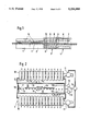
- FIG. 1 shows an apparatus of the invention in a schematic vertical section.
- FIG. 2 is a more detailed view in a schematic vertical section showing a heat-strengthening station included in the apparatus.
- FIG. 3 shows a heat-strengthening station of the invention in a schematic cross-section.
- FIG. 4 is a schematic side view showing the openability of a heat-strengthening station of the invention.
- FIG. 5 is schematic side view showing an alternative embodiment for the heat-strengthening station.
- FIG. 6 illustrates heat-strengthening curves for various glass thicknesses.
- FIG. 7 shows the temperature of 10 mm glass as a function of time at various stages of heat strengthening. In association with the glass temperature curve there is also shown the temperature of each treating station and a coefficient of heat transfer between glass and ambient air.
- FIG. 8 is similar to FIG. 7 but deals with 12 mm glass where heat strengthening was carried out by using a test apparatus of the invention.
- the apparatus shown in FIG. 1 includes a first furnace section 1, a second furnace section 2, a heat-strengthening station 3, and a cooling station 4.
- a conveyor included in furnace 1, 2 comprises horizontal rollers 5 and a conveyor included in stations or sections 3, 4 comprises horizontal rollers 6.
- Rollers 5 and 6 are used to carry glass sheets from one section to another and, in addition, by rotating the rollers in a reciprocating fashion, the glass sheets are set in an oscillating motion in each section.
- Heating elements 19 included in furnace sections 1 and 2 can be e.g. resistance elements but it is naturally possible to employ also other types of sources of heat, such as gas burners.
- Stations 3 and 4 are provided with cooling air nozzles 8 on either side of a top surface level 7 of a conveyor consisting of rollers 6.
- said nozzles 8 are associated with nozzle housings 18, the cooling air being supplied therein by means of blowers or fans 11 and 12.
- blowers or fans 11 and 12 Naturally, it is also possible to employ compressors or combinations of fans and compressors depending on desired blast pressures and the actual size of a jet orifice.
- said nozzles 8 can be identical to those typically used in the quenching stations of tempering plants. These have been generally known and used in various configurations for decades and, thus, such construction is not described further in this context.
- a novel feature in the invention is the fitting of cooling panels 9 between blast nozzles 8 and a glass sheet 15 to be heat-strengthened.
- the cooling panels 9 are made of a highly heat-conductive material, preferably a metal, and secured to nozzle housings 18.
- the cooling panels 9 confine therebetween a heat-strengthening chamber 10, whose temperature can be controlled by cooling said upper and lower cooling panels 9 by means of cooling air jets.
- the power of fans 11 and 12 is controlled by means of temperature sensors 13', connected with thermostats 13 and a regulator 14. Said sensors 13' can be adapted to measure temperature between cooling panels 9 or glass temperature or both.
- the temperature of space 10 can be controlled by adjusting the distance of panels 9 from glass sheet 15.
- the chamber space 10 is designed as a closed environment by having its ends and sides thermally insulated. Thus, heat is transmitted in a controlled fashion over the entire surface area of glass sheet 15 to cooled metal panels 9. The transmission of heat is effected by means of both radiation and convection.
- a thermal insulation barrier confining space 10 at the ends and sides, and serving also as a flow barrier, can be designed by using fixed or movable walls.
- FIG. 2 illustrates a vertically movable gate 16 in the end wall.
- the insulation and flow barrier can also comprise an air screen 17 which closes after a glass sheet has arrived in the chamber space. It is also possible that, particularly with small-size glasses, the space confined by said panels has open sides.
- Metal panels 9 are preferably solid continuous plates and the material thereof is e.g. AISI 304 2BA Steel.
- One or each surface of cooling panels 9 can be provided with heat-exchange ribs 9.2 for intensifying the transmission of heat. This may be necessary as heat must be removed from chamber 10 at a rate of 450 kW (which is roughly equivalent to the cooling capacity of the refrigeration machinery of an indoor ice-hockey rink).
- the surface area of heat-exchange ribs 9.2 per unit area of cooling panel 9 be larger in the central area of a cooling panel than in the end and/or side edges.
- the density and/or height of heat-exchange ribs 9.2 it is possible to eliminate the irregularities detected in cooling. It is also possible to employ local heating resistances e.g. between rollers 6 for controlling the regularity of cooling. When heat-strengthening small individual pieces of glass, such resistances can be used at the same time for preheating the chamber space, if necessary.
- the nozzle housings along with panels 9 thereof By arranging the nozzle housings along with panels 9 thereof to be pivotable by the area of one of the side edges thereof or, as shown in FIG. 4, by the area of at least one of the ends thereof to lie at a major distance from conveyor 6, the bits of broken glass can be readily removed.
- Such an arrangement is shown, for example, in U.S. Pat. No. 5,078,744 and is shown as the adjusting means 100 in FIG. 4.
- panels 9 are continuous over the entire surface area of heat-strengthening station 3 but the panels can be made up by smaller panel units 9.1, as shown in FIG. 5.
- the material and thickness of various panel units 9.1 can be selected to be different e.g. in the central and marginal areas.
- Another special feature associated with a heat-strengthening apparatus of the invention is that one and the same apparatus can be readily used also for tempering glasses having varying thicknesses.
- the glass heat-strengthening process involves the heat-strengthening of glass in station 3 and then rapidly cooling it in station 4 by means of an effective cooling air blast, as shown by the curves of FIGS. 7 and 8. If, instead of heat strengthening, the glass is to be tempered, it will be driven through heat-strengthening station 3 directly into cooling station 4 for carrying out an effective quenching operation. This can be done on all types of glass having a thickness over 3 mm.
- the apparatus is capable of tempering also 3 mm thick glass by designing cooling panels 9 to be readily removable whereby, with panels 9 removed, the quenching operation can be carried out in station 3.
- cooling panels 9 to be readily removable whereby, with panels 9 removed, the quenching operation can be carried out in station 3.
Abstract
Description
Claims (18)
Applications Claiming Priority (2)
| Application Number | Priority Date | Filing Date | Title |
|---|---|---|---|
| FI903362A FI86055C (en) | 1990-07-04 | 1990-07-04 | Device for thermosetting of glass sheets |
| FI903362 | 1990-07-04 |
Publications (1)
| Publication Number | Publication Date |
|---|---|
| US5236488A true US5236488A (en) | 1993-08-17 |
Family
ID=8530744
Family Applications (1)
| Application Number | Title | Priority Date | Filing Date |
|---|---|---|---|
| US07/721,680 Expired - Lifetime US5236488A (en) | 1990-07-04 | 1991-06-26 | Method and apparatus for heat-strengthening glass sheets |
Country Status (7)
| Country | Link |
|---|---|
| US (1) | US5236488A (en) |
| EP (1) | EP0464805B1 (en) |
| JP (1) | JP3253322B2 (en) |
| AU (1) | AU646867B2 (en) |
| CA (1) | CA2045035C (en) |
| DE (1) | DE69122320T2 (en) |
| FI (1) | FI86055C (en) |
Cited By (20)
| Publication number | Priority date | Publication date | Assignee | Title |
|---|---|---|---|---|
| US5882371A (en) * | 1996-07-12 | 1999-03-16 | Asahi Glass Company Ltd. | Method for heat-treating a glass substrate |
| US6279350B1 (en) * | 1996-05-22 | 2001-08-28 | Uniglass Engineering Oy | Adjusting cooling air in glass tempering machine |
| US6427488B1 (en) * | 1995-01-10 | 2002-08-06 | Tamglass Engineering Oy | Method for heating glass sheets to be tempered or heat-strengthened |
| US7000433B1 (en) * | 1999-05-17 | 2006-02-21 | Technopat Ag | Device for heating plates of glass |
| US20080127678A1 (en) * | 2006-12-01 | 2008-06-05 | Glasstech, Inc. | Method and apparatus for quenching formed glass sheets |
| WO2015172723A1 (en) * | 2014-05-15 | 2015-11-19 | Luoyang Landglass Technology Co., Ltd. | Tempering and cooling system for a tempered glass |
| US9296638B2 (en) | 2014-07-31 | 2016-03-29 | Corning Incorporated | Thermally tempered glass and methods and apparatuses for thermal tempering of glass |
| WO2017132702A1 (en) * | 2016-01-31 | 2017-08-03 | Corning Incorporated | Thermally strengthened glass sheets having small-scale index or birefringence patterns |
| US10611664B2 (en) | 2014-07-31 | 2020-04-07 | Corning Incorporated | Thermally strengthened architectural glass and related systems and methods |
| US10988411B2 (en) * | 2017-10-25 | 2021-04-27 | Wuhan China Star Optoelectronics Technology Co., Ltd. | Method and apparatus for drying and cooling glass substrate |
| US11097974B2 (en) | 2014-07-31 | 2021-08-24 | Corning Incorporated | Thermally strengthened consumer electronic glass and related systems and methods |
| CN113698080A (en) * | 2021-02-04 | 2021-11-26 | 佛山市顺德区优畅玻璃有限公司 | Preparation process of high-strength toughened glass |
| US20210380461A1 (en) * | 2020-06-08 | 2021-12-09 | Glaston Finland Oy | Method and device for tempering glass sheets |
| CN113896409A (en) * | 2021-11-08 | 2022-01-07 | 盐城亿高供热设备有限公司 | Forced cooling glass toughening furnace for refrigerator |
| US11479495B2 (en) * | 2017-08-07 | 2022-10-25 | Luoyang Landglass Technology Co., Ltd. | Actuating mechanism control method for glass plate tempering process |
| US11485673B2 (en) | 2017-08-24 | 2022-11-01 | Corning Incorporated | Glasses with improved tempering capabilities |
| US11643355B2 (en) | 2016-01-12 | 2023-05-09 | Corning Incorporated | Thin thermally and chemically strengthened glass-based articles |
| US11697617B2 (en) | 2019-08-06 | 2023-07-11 | Corning Incorporated | Glass laminate with buried stress spikes to arrest cracks and methods of making the same |
| US11708296B2 (en) | 2017-11-30 | 2023-07-25 | Corning Incorporated | Non-iox glasses with high coefficient of thermal expansion and preferential fracture behavior for thermal tempering |
| US11795102B2 (en) | 2016-01-26 | 2023-10-24 | Corning Incorporated | Non-contact coated glass and related coating system and method |
Families Citing this family (5)
| Publication number | Priority date | Publication date | Assignee | Title |
|---|---|---|---|---|
| FI86406C (en) * | 1991-01-11 | 1992-08-25 | Tamglass Oy | Device for thermosetting of glass sheets |
| DE102008005283B4 (en) * | 2008-01-19 | 2009-10-29 | Schott Solar Gmbh | A method of making a transparent metal oxide coated glass sheet for a photovoltaic module and such a coated glass sheet |
| EP3022159B1 (en) * | 2013-07-16 | 2019-03-20 | Corning Incorporated | Apparatus and method for bending thin glass |
| FI126763B (en) * | 2013-09-25 | 2017-05-15 | Glaston Finland Oy | Method and apparatus for curing glass sheets |
| EP3408235A1 (en) * | 2016-01-28 | 2018-12-05 | Corning Incorporated | Processes for thermal strengthening of glass using liquid conduction |
Citations (9)
| Publication number | Priority date | Publication date | Assignee | Title |
|---|---|---|---|---|
| DE529735C (en) * | 1929-09-21 | 1931-07-17 | Saint Gobain | Method and device for hardening individual glass sheets |
| US2188401A (en) * | 1937-06-15 | 1940-01-30 | Libbey Owens Ford Glass Co | Apparatus for tempering glass |
| US3304166A (en) * | 1962-01-19 | 1967-02-14 | Glaceries Reunies Sa | Fluid quenching apparatus for producing a differentially toughened zone in a toughened glass |
| US4225333A (en) * | 1978-11-15 | 1980-09-30 | Ppg Industries, Inc. | Glass sheet tempering apparatus |
| US4236909A (en) * | 1979-05-18 | 1980-12-02 | Ppg Industries, Inc. | Producing glass sheets having improved break patterns |
| US4400194A (en) * | 1982-02-10 | 1983-08-23 | Ppg Industries, Inc. | Method and apparatus for producing heat-strengthened glass sheets having improved break patterns |
| EP0246123A1 (en) * | 1986-04-16 | 1987-11-19 | Saint Gobain Vitrage International | Apparatus for tempering glass sheets |
| GB2191998A (en) * | 1986-06-26 | 1987-12-31 | Pilkington Brothers Plc | Heat strengthened glass |
| US5078774A (en) * | 1991-01-11 | 1992-01-07 | Tamglass Oy | Method and apparatus for heat-strengthening glass sheets |
-
1990
- 1990-07-04 FI FI903362A patent/FI86055C/en active IP Right Grant
-
1991
- 1991-06-19 AU AU79105/91A patent/AU646867B2/en not_active Ceased
- 1991-06-20 CA CA002045035A patent/CA2045035C/en not_active Expired - Fee Related
- 1991-06-26 US US07/721,680 patent/US5236488A/en not_active Expired - Lifetime
- 1991-07-03 EP EP91111060A patent/EP0464805B1/en not_active Expired - Lifetime
- 1991-07-03 DE DE69122320T patent/DE69122320T2/en not_active Expired - Fee Related
- 1991-07-04 JP JP19064291A patent/JP3253322B2/en not_active Expired - Fee Related
Patent Citations (14)
| Publication number | Priority date | Publication date | Assignee | Title |
|---|---|---|---|---|
| DE529735C (en) * | 1929-09-21 | 1931-07-17 | Saint Gobain | Method and device for hardening individual glass sheets |
| US1944625A (en) * | 1929-09-21 | 1934-01-23 | American Securit Co | Apparatus for tempering glass sheets |
| US2188401A (en) * | 1937-06-15 | 1940-01-30 | Libbey Owens Ford Glass Co | Apparatus for tempering glass |
| US3304166A (en) * | 1962-01-19 | 1967-02-14 | Glaceries Reunies Sa | Fluid quenching apparatus for producing a differentially toughened zone in a toughened glass |
| DE1285687B (en) * | 1962-01-19 | 1968-12-19 | Glaceries Reunies Sa | Device for hardening a pane of glass |
| US4225333A (en) * | 1978-11-15 | 1980-09-30 | Ppg Industries, Inc. | Glass sheet tempering apparatus |
| US4236909A (en) * | 1979-05-18 | 1980-12-02 | Ppg Industries, Inc. | Producing glass sheets having improved break patterns |
| US4400194A (en) * | 1982-02-10 | 1983-08-23 | Ppg Industries, Inc. | Method and apparatus for producing heat-strengthened glass sheets having improved break patterns |
| EP0246123A1 (en) * | 1986-04-16 | 1987-11-19 | Saint Gobain Vitrage International | Apparatus for tempering glass sheets |
| US4816058A (en) * | 1986-04-16 | 1989-03-28 | Saint-Gobain Vitrage "Les Miroirs" | Blow box for glass tempering |
| US4874418A (en) * | 1986-04-16 | 1989-10-17 | Saint-Gobain Vitrage "Les Miroirs" | Blow box for glass tempering |
| GB2191998A (en) * | 1986-06-26 | 1987-12-31 | Pilkington Brothers Plc | Heat strengthened glass |
| US4759788A (en) * | 1986-06-26 | 1988-07-26 | Pilkington Brothers P.L.C. | Heat strengthened glass |
| US5078774A (en) * | 1991-01-11 | 1992-01-07 | Tamglass Oy | Method and apparatus for heat-strengthening glass sheets |
Cited By (33)
| Publication number | Priority date | Publication date | Assignee | Title |
|---|---|---|---|---|
| US6427488B1 (en) * | 1995-01-10 | 2002-08-06 | Tamglass Engineering Oy | Method for heating glass sheets to be tempered or heat-strengthened |
| US6279350B1 (en) * | 1996-05-22 | 2001-08-28 | Uniglass Engineering Oy | Adjusting cooling air in glass tempering machine |
| US5882371A (en) * | 1996-07-12 | 1999-03-16 | Asahi Glass Company Ltd. | Method for heat-treating a glass substrate |
| US7000433B1 (en) * | 1999-05-17 | 2006-02-21 | Technopat Ag | Device for heating plates of glass |
| US20080127678A1 (en) * | 2006-12-01 | 2008-06-05 | Glasstech, Inc. | Method and apparatus for quenching formed glass sheets |
| US8074473B2 (en) * | 2006-12-01 | 2011-12-13 | Glasstech, Inc. | Method for quenching formed glass sheets |
| US20120042695A1 (en) * | 2006-12-01 | 2012-02-23 | Glasstech, Inc. | Apparatus for quenching formed glass sheets |
| AU2015258588B2 (en) * | 2014-05-15 | 2017-11-30 | Luoyang Landglass Technology Co., Ltd. | Tempering and cooling system for a tempered glass |
| WO2015172723A1 (en) * | 2014-05-15 | 2015-11-19 | Luoyang Landglass Technology Co., Ltd. | Tempering and cooling system for a tempered glass |
| US20170066678A1 (en) * | 2014-05-15 | 2017-03-09 | Luoyang Landglass Technology Co., Ltd. | Tempering and Cooling System for a Tempered Glass |
| US10005691B2 (en) | 2014-07-31 | 2018-06-26 | Corning Incorporated | Damage resistant glass article |
| US11097974B2 (en) | 2014-07-31 | 2021-08-24 | Corning Incorporated | Thermally strengthened consumer electronic glass and related systems and methods |
| US9783448B2 (en) | 2014-07-31 | 2017-10-10 | Corning Incorporated | Thin dicing glass article |
| US9802853B2 (en) | 2014-07-31 | 2017-10-31 | Corning Incorporated | Fictive temperature in damage-resistant glass having improved mechanical characteristics |
| US11891324B2 (en) | 2014-07-31 | 2024-02-06 | Corning Incorporated | Thermally strengthened consumer electronic glass and related systems and methods |
| US9975801B2 (en) | 2014-07-31 | 2018-05-22 | Corning Incorporated | High strength glass having improved mechanical characteristics |
| US9296638B2 (en) | 2014-07-31 | 2016-03-29 | Corning Incorporated | Thermally tempered glass and methods and apparatuses for thermal tempering of glass |
| US10077204B2 (en) | 2014-07-31 | 2018-09-18 | Corning Incorporated | Thin safety glass having improved mechanical characteristics |
| US10233111B2 (en) | 2014-07-31 | 2019-03-19 | Corning Incorporated | Thermally tempered glass and methods and apparatuses for thermal tempering of glass |
| US10611664B2 (en) | 2014-07-31 | 2020-04-07 | Corning Incorporated | Thermally strengthened architectural glass and related systems and methods |
| US9776905B2 (en) | 2014-07-31 | 2017-10-03 | Corning Incorporated | Highly strengthened glass article |
| US11643355B2 (en) | 2016-01-12 | 2023-05-09 | Corning Incorporated | Thin thermally and chemically strengthened glass-based articles |
| US11795102B2 (en) | 2016-01-26 | 2023-10-24 | Corning Incorporated | Non-contact coated glass and related coating system and method |
| WO2017132702A1 (en) * | 2016-01-31 | 2017-08-03 | Corning Incorporated | Thermally strengthened glass sheets having small-scale index or birefringence patterns |
| US11479495B2 (en) * | 2017-08-07 | 2022-10-25 | Luoyang Landglass Technology Co., Ltd. | Actuating mechanism control method for glass plate tempering process |
| US11485673B2 (en) | 2017-08-24 | 2022-11-01 | Corning Incorporated | Glasses with improved tempering capabilities |
| US10988411B2 (en) * | 2017-10-25 | 2021-04-27 | Wuhan China Star Optoelectronics Technology Co., Ltd. | Method and apparatus for drying and cooling glass substrate |
| US11708296B2 (en) | 2017-11-30 | 2023-07-25 | Corning Incorporated | Non-iox glasses with high coefficient of thermal expansion and preferential fracture behavior for thermal tempering |
| US11697617B2 (en) | 2019-08-06 | 2023-07-11 | Corning Incorporated | Glass laminate with buried stress spikes to arrest cracks and methods of making the same |
| US20210380461A1 (en) * | 2020-06-08 | 2021-12-09 | Glaston Finland Oy | Method and device for tempering glass sheets |
| CN113698080A (en) * | 2021-02-04 | 2021-11-26 | 佛山市顺德区优畅玻璃有限公司 | Preparation process of high-strength toughened glass |
| CN113896409A (en) * | 2021-11-08 | 2022-01-07 | 盐城亿高供热设备有限公司 | Forced cooling glass toughening furnace for refrigerator |
| CN113896409B (en) * | 2021-11-08 | 2022-05-03 | 盐城亿高供热设备有限公司 | Forced cooling glass toughening furnace for refrigerator |
Also Published As
| Publication number | Publication date |
|---|---|
| FI86055C (en) | 1992-07-10 |
| CA2045035A1 (en) | 1992-01-05 |
| AU7910591A (en) | 1992-01-09 |
| FI86055B (en) | 1992-03-31 |
| EP0464805A3 (en) | 1992-04-01 |
| CA2045035C (en) | 2002-02-26 |
| DE69122320D1 (en) | 1996-10-31 |
| DE69122320T2 (en) | 1997-02-06 |
| FI903362A (en) | 1992-01-05 |
| EP0464805A2 (en) | 1992-01-08 |
| JP3253322B2 (en) | 2002-02-04 |
| EP0464805B1 (en) | 1996-09-25 |
| FI903362A0 (en) | 1990-07-04 |
| JPH05116975A (en) | 1993-05-14 |
| AU646867B2 (en) | 1994-03-10 |
Similar Documents
| Publication | Publication Date | Title |
|---|---|---|
| US5236488A (en) | Method and apparatus for heat-strengthening glass sheets | |
| EP0761614B1 (en) | Method for heating, forming and tempering a glass sheet | |
| US5948132A (en) | Glass sheet strip annealing method | |
| US8074473B2 (en) | Method for quenching formed glass sheets | |
| US4300937A (en) | Quench devices, glass tempering furnaces, and methods of utilizing same | |
| US4946491A (en) | Method and apparatus for glass tempering | |
| US4297121A (en) | Glass tempering furnaces and systems | |
| CN105246847B (en) | Using microwave focused beam acts heating heating and mould system | |
| EP0761612B1 (en) | Method for heating a glass sheet | |
| EP0761613B1 (en) | Method for heating and forming a glass sheet | |
| US5656053A (en) | Method for heating and forming a glass sheet | |
| US4182619A (en) | Method of toughening glass sheets | |
| JP3505755B2 (en) | Glass plate heat treatment equipment | |
| US4620864A (en) | Glass sheet tempering utilizing heating and quenching performed in ambient at superatmospheric pressure | |
| PL175890B1 (en) | Method of and system for obtaining convex glass panels | |
| US3806331A (en) | Glass heating and tempering apparatus | |
| TWI749009B (en) | Apparatus for tempering glass sheets | |
| CA1108860A (en) | Position selectable glass surface temperature scanner | |
| US4681616A (en) | Glass sheet tempering method and furnace | |
| GB2320021A (en) | Frame and oven for sag-bending glass | |
| US7216511B2 (en) | Furnace apparatus and method for tempering low emissivity glass | |
| FI71917B (en) | HAERDNING AV GLASSKIVA VARVID ANVAENDS SLAECKNING MED GAS MED STOR TAETHET | |
| EP0499026B1 (en) | Apparatus for heat-strengthening glass sheet | |
| US4983201A (en) | Method and apparatus in a glass sheet bending furnace for preventing the deflection of mould wagon bearing rails | |
| US3454388A (en) | Oscillatory spray tempering apparatus |
Legal Events
| Date | Code | Title | Description |
|---|---|---|---|
| AS | Assignment |
Owner name: TAMGLASS OY Free format text: ASSIGNMENT OF ASSIGNORS INTEREST.;ASSIGNOR:VEHMAS, JUKKA H.;REEL/FRAME:005823/0878 Effective date: 19910619 |
|
| AS | Assignment |
Owner name: TAMGLASS ENGINEERING OY, FINLAND Free format text: ASSIGNMENT OF ASSIGNORS INTEREST.;ASSIGNOR:TAMGLASS OY;REEL/FRAME:006312/0325 Effective date: 19921016 |
|
| STCF | Information on status: patent grant |
Free format text: PATENTED CASE |
|
| FEPP | Fee payment procedure |
Free format text: PAYOR NUMBER ASSIGNED (ORIGINAL EVENT CODE: ASPN); ENTITY STATUS OF PATENT OWNER: LARGE ENTITY Free format text: PAYER NUMBER DE-ASSIGNED (ORIGINAL EVENT CODE: RMPN); ENTITY STATUS OF PATENT OWNER: LARGE ENTITY |
|
| FEPP | Fee payment procedure |
Free format text: PAYOR NUMBER ASSIGNED (ORIGINAL EVENT CODE: ASPN); ENTITY STATUS OF PATENT OWNER: LARGE ENTITY |
|
| FPAY | Fee payment |
Year of fee payment: 4 |
|
| FPAY | Fee payment |
Year of fee payment: 8 |
|
| FPAY | Fee payment |
Year of fee payment: 12 |