US5242295A - Combustion method for simultaneous control of nitrogen oxides and products of incomplete combustion - Google Patents
Combustion method for simultaneous control of nitrogen oxides and products of incomplete combustion Download PDFInfo
- Publication number
- US5242295A US5242295A US07/970,881 US97088192A US5242295A US 5242295 A US5242295 A US 5242295A US 97088192 A US97088192 A US 97088192A US 5242295 A US5242295 A US 5242295A
- Authority
- US
- United States
- Prior art keywords
- combustion
- oxidant
- combustion zone
- fuel
- high velocity
- Prior art date
- Legal status (The legal status is an assumption and is not a legal conclusion. Google has not performed a legal analysis and makes no representation as to the accuracy of the status listed.)
- Expired - Lifetime
Links
Images
Classifications
-
- F—MECHANICAL ENGINEERING; LIGHTING; HEATING; WEAPONS; BLASTING
- F23—COMBUSTION APPARATUS; COMBUSTION PROCESSES
- F23N—REGULATING OR CONTROLLING COMBUSTION
- F23N5/00—Systems for controlling combustion
- F23N5/003—Systems for controlling combustion using detectors sensitive to combustion gas properties
-
- F—MECHANICAL ENGINEERING; LIGHTING; HEATING; WEAPONS; BLASTING
- F23—COMBUSTION APPARATUS; COMBUSTION PROCESSES
- F23G—CREMATION FURNACES; CONSUMING WASTE PRODUCTS BY COMBUSTION
- F23G5/00—Incineration of waste; Incinerator constructions; Details, accessories or control therefor
- F23G5/08—Incineration of waste; Incinerator constructions; Details, accessories or control therefor having supplementary heating
- F23G5/14—Incineration of waste; Incinerator constructions; Details, accessories or control therefor having supplementary heating including secondary combustion
- F23G5/16—Incineration of waste; Incinerator constructions; Details, accessories or control therefor having supplementary heating including secondary combustion in a separate combustion chamber
-
- F—MECHANICAL ENGINEERING; LIGHTING; HEATING; WEAPONS; BLASTING
- F23—COMBUSTION APPARATUS; COMBUSTION PROCESSES
- F23L—SUPPLYING AIR OR NON-COMBUSTIBLE LIQUIDS OR GASES TO COMBUSTION APPARATUS IN GENERAL ; VALVES OR DAMPERS SPECIALLY ADAPTED FOR CONTROLLING AIR SUPPLY OR DRAUGHT IN COMBUSTION APPARATUS; INDUCING DRAUGHT IN COMBUSTION APPARATUS; TOPS FOR CHIMNEYS OR VENTILATING SHAFTS; TERMINALS FOR FLUES
- F23L7/00—Supplying non-combustible liquids or gases, other than air, to the fire, e.g. oxygen, steam
-
- F—MECHANICAL ENGINEERING; LIGHTING; HEATING; WEAPONS; BLASTING
- F23—COMBUSTION APPARATUS; COMBUSTION PROCESSES
- F23N—REGULATING OR CONTROLLING COMBUSTION
- F23N1/00—Regulating fuel supply
- F23N1/02—Regulating fuel supply conjointly with air supply
- F23N1/022—Regulating fuel supply conjointly with air supply using electronic means
-
- F—MECHANICAL ENGINEERING; LIGHTING; HEATING; WEAPONS; BLASTING
- F23—COMBUSTION APPARATUS; COMBUSTION PROCESSES
- F23C—METHODS OR APPARATUS FOR COMBUSTION USING FLUID FUEL OR SOLID FUEL SUSPENDED IN A CARRIER GAS OR AIR
- F23C2900/00—Special features of, or arrangements for combustion apparatus using fluid fuels or solid fuels suspended in air; Combustion processes therefor
- F23C2900/06041—Staged supply of oxidant
-
- F—MECHANICAL ENGINEERING; LIGHTING; HEATING; WEAPONS; BLASTING
- F23—COMBUSTION APPARATUS; COMBUSTION PROCESSES
- F23C—METHODS OR APPARATUS FOR COMBUSTION USING FLUID FUEL OR SOLID FUEL SUSPENDED IN A CARRIER GAS OR AIR
- F23C2900/00—Special features of, or arrangements for combustion apparatus using fluid fuels or solid fuels suspended in air; Combustion processes therefor
- F23C2900/09002—Specific devices inducing or forcing flue gas recirculation
-
- F—MECHANICAL ENGINEERING; LIGHTING; HEATING; WEAPONS; BLASTING
- F23—COMBUSTION APPARATUS; COMBUSTION PROCESSES
- F23G—CREMATION FURNACES; CONSUMING WASTE PRODUCTS BY COMBUSTION
- F23G2202/00—Combustion
- F23G2202/10—Combustion in two or more stages
- F23G2202/101—Combustion in two or more stages with controlled oxidant supply
-
- F—MECHANICAL ENGINEERING; LIGHTING; HEATING; WEAPONS; BLASTING
- F23—COMBUSTION APPARATUS; COMBUSTION PROCESSES
- F23G—CREMATION FURNACES; CONSUMING WASTE PRODUCTS BY COMBUSTION
- F23G2202/00—Combustion
- F23G2202/10—Combustion in two or more stages
- F23G2202/102—Combustion in two or more stages with supplementary heating
-
- F—MECHANICAL ENGINEERING; LIGHTING; HEATING; WEAPONS; BLASTING
- F23—COMBUSTION APPARATUS; COMBUSTION PROCESSES
- F23G—CREMATION FURNACES; CONSUMING WASTE PRODUCTS BY COMBUSTION
- F23G2207/00—Control
- F23G2207/10—Arrangement of sensing devices
- F23G2207/103—Arrangement of sensing devices for oxygen
-
- F—MECHANICAL ENGINEERING; LIGHTING; HEATING; WEAPONS; BLASTING
- F23—COMBUSTION APPARATUS; COMBUSTION PROCESSES
- F23G—CREMATION FURNACES; CONSUMING WASTE PRODUCTS BY COMBUSTION
- F23G2209/00—Specific waste
- F23G2209/12—Sludge, slurries or mixtures of liquids
-
- F—MECHANICAL ENGINEERING; LIGHTING; HEATING; WEAPONS; BLASTING
- F23—COMBUSTION APPARATUS; COMBUSTION PROCESSES
- F23G—CREMATION FURNACES; CONSUMING WASTE PRODUCTS BY COMBUSTION
- F23G2209/00—Specific waste
- F23G2209/24—Contaminated soil; foundry sand
-
- F—MECHANICAL ENGINEERING; LIGHTING; HEATING; WEAPONS; BLASTING
- F23—COMBUSTION APPARATUS; COMBUSTION PROCESSES
- F23G—CREMATION FURNACES; CONSUMING WASTE PRODUCTS BY COMBUSTION
- F23G2900/00—Special features of, or arrangements for incinerators
- F23G2900/52001—Rotary drums with co-current flows of waste and gas
-
- F—MECHANICAL ENGINEERING; LIGHTING; HEATING; WEAPONS; BLASTING
- F23—COMBUSTION APPARATUS; COMBUSTION PROCESSES
- F23L—SUPPLYING AIR OR NON-COMBUSTIBLE LIQUIDS OR GASES TO COMBUSTION APPARATUS IN GENERAL ; VALVES OR DAMPERS SPECIALLY ADAPTED FOR CONTROLLING AIR SUPPLY OR DRAUGHT IN COMBUSTION APPARATUS; INDUCING DRAUGHT IN COMBUSTION APPARATUS; TOPS FOR CHIMNEYS OR VENTILATING SHAFTS; TERMINALS FOR FLUES
- F23L2900/00—Special arrangements for supplying or treating air or oxidant for combustion; Injecting inert gas, water or steam into the combustion chamber
- F23L2900/07005—Injecting pure oxygen or oxygen enriched air
-
- F—MECHANICAL ENGINEERING; LIGHTING; HEATING; WEAPONS; BLASTING
- F23—COMBUSTION APPARATUS; COMBUSTION PROCESSES
- F23L—SUPPLYING AIR OR NON-COMBUSTIBLE LIQUIDS OR GASES TO COMBUSTION APPARATUS IN GENERAL ; VALVES OR DAMPERS SPECIALLY ADAPTED FOR CONTROLLING AIR SUPPLY OR DRAUGHT IN COMBUSTION APPARATUS; INDUCING DRAUGHT IN COMBUSTION APPARATUS; TOPS FOR CHIMNEYS OR VENTILATING SHAFTS; TERMINALS FOR FLUES
- F23L2900/00—Special arrangements for supplying or treating air or oxidant for combustion; Injecting inert gas, water or steam into the combustion chamber
- F23L2900/07006—Control of the oxygen supply
-
- F—MECHANICAL ENGINEERING; LIGHTING; HEATING; WEAPONS; BLASTING
- F23—COMBUSTION APPARATUS; COMBUSTION PROCESSES
- F23L—SUPPLYING AIR OR NON-COMBUSTIBLE LIQUIDS OR GASES TO COMBUSTION APPARATUS IN GENERAL ; VALVES OR DAMPERS SPECIALLY ADAPTED FOR CONTROLLING AIR SUPPLY OR DRAUGHT IN COMBUSTION APPARATUS; INDUCING DRAUGHT IN COMBUSTION APPARATUS; TOPS FOR CHIMNEYS OR VENTILATING SHAFTS; TERMINALS FOR FLUES
- F23L2900/00—Special arrangements for supplying or treating air or oxidant for combustion; Injecting inert gas, water or steam into the combustion chamber
- F23L2900/07008—Injection of water into the combustion chamber
-
- F—MECHANICAL ENGINEERING; LIGHTING; HEATING; WEAPONS; BLASTING
- F23—COMBUSTION APPARATUS; COMBUSTION PROCESSES
- F23N—REGULATING OR CONTROLLING COMBUSTION
- F23N2237/00—Controlling
- F23N2237/16—Controlling secondary air
-
- Y—GENERAL TAGGING OF NEW TECHNOLOGICAL DEVELOPMENTS; GENERAL TAGGING OF CROSS-SECTIONAL TECHNOLOGIES SPANNING OVER SEVERAL SECTIONS OF THE IPC; TECHNICAL SUBJECTS COVERED BY FORMER USPC CROSS-REFERENCE ART COLLECTIONS [XRACs] AND DIGESTS
- Y02—TECHNOLOGIES OR APPLICATIONS FOR MITIGATION OR ADAPTATION AGAINST CLIMATE CHANGE
- Y02E—REDUCTION OF GREENHOUSE GAS [GHG] EMISSIONS, RELATED TO ENERGY GENERATION, TRANSMISSION OR DISTRIBUTION
- Y02E20/00—Combustion technologies with mitigation potential
- Y02E20/34—Indirect CO2mitigation, i.e. by acting on non CO2directly related matters of the process, e.g. pre-heating or heat recovery
Definitions
- This invention relates generally to combustion and is particularly applicable to the incineration of waste such as hazardous waste.
- the oxygen may be injected into the combustion zone in the form of air, oxygen-enriched air or technically pure oxygen.
- the higher is the oxygen concentration of the oxidant the greater is the tendency for the subsequent combustion to form nitrogen oxides (NO x ) which are themselves undesirable pollutants resulting from combustion processes.
- PICs environmental pollutant
- NO x nitrogen oxides
- a method for combusting material with controlled generation of both nitrogen oxides and products of incomplete combustion comprising:
- Another aspect of this invention comprises:
- a method for operating a pyrolytic combustion zone for simultaneously controlling the generation of both nitrogen oxides and products of incomplete combustion comprising:
- oxidant jet diameter means the diameter of the oxidant stream at the point where it emerges from the injection device such as a nozzle.
- smoke means a black substance, comprising very small particles of carbon or heavy hydrocarbons, which appears in smoke often resulting from incomplete combustion.
- blow-off velocity means the maximum oxidant jet velocity, as measured at the orifice, that will maintain a flame attached to the orifice when the oxidant jet is surrounded by gaseous fuel.
- FIG. 1 is a simplified schematic diagram of one embodiment of the invention carried out in conjunction with the incineration of hazardous waste.
- FIG. 2 is a more detailed view of the embodiment illustrated in FIG. 1 showing in greater detail the injection of high velocity oxidant and the aspiration thereinto of exhaust gases.
- combustible material is provided into a first combustion zone.
- the combustible material or fuel may be in solid, liquid, gaseous or mixed phase form and may be provided into the first combustion zone separately from or with the oxidant for combustion.
- the invention will have particular utility with combustible material which has a highly variable heating value per unit volume and/or which is supplied into the first combustion zone at a highly variable rate.
- Examples of combustible material or fuel which may be employed with the combustion method of this invention include coal, wood, lignite, heavy oil, trash, solid and/or liquid waste, aqueous plant effluent and hazardous waste.
- gaseous fuel will volatize from the solid or liquid.
- the oxidant employed in the first combustion zone may be air, oxygen-enriched air and/or technically pure oxygen and may be supplied with the combustible material such as through a burner or as a separate oxidant stream such as through a lance. Air may also pass into the first combustion zone by infiltration.
- the combustible material is combusted to produce gaseous exhaust which comprises products of complete combustion, such as carbon dioxide and water vapor, and also products of incomplete combustion.
- a product of incomplete combustion or PIC may be defined as a species which can undergo oxidation or further oxidation under combustion zone conditions of temperature and pressure. Examples of well known PICs include carbon monoxide, hydrocarbons, soot and chlorinated hydrocarbons such as dioxins and furans.
- the gaseous exhaust is then passed from the first combustion zone into a second combustion zone which may be integral with the first combustion zone or may be separate from the first combustion zone and connected therewith by a conduit or other passageway.
- the first combustion zone may be the primary combustion chamber of an incineration system and the second combustion zone may be the secondary combustion chamber of such a system.
- the primary combustion chamber of an incineration system comprises a rotary kiln.
- the primary combustion chamber is often used for handling solid or sludge waste while the secondary combustion chamber is used to treat the gaseous exhaust from the primary combustion chamber to ensure good destruction of the waste by operating at a higher temperature and providing sufficient gas residence time to ensure the destruction of the waste.
- the high velocity oxidant is technically pure oxygen having an oxygen concentration of 99.5 percent or more.
- the high velocity oxidant will have a velocity of at least 300 feet per second and generally the velocity will be within the range of from 400 to 1500 feet per second. The velocity is sufficiently high to cause exhaust gases to aspirate into the oxidant. The aspiration may occur within the second combustion zone and/or may occur upstream of the second combustion zone.
- the aspiration enables the exhaust gas and in particular the PICs within the exhaust gas to intimately mix with the oxidant resulting in the subsequent combustion being stable with the avoidance of hot spots which would favor NO x formation and would cause refractory damage.
- the products of complete combustion from the combustion reaction e.g. carbon dioxide and water vapor, within the exhaust gas which are also aspirated into the high velocity oxidant serve as ballast for the combustion reaction whereby the combustion reaction is spread out and heat from the combustion reaction is absorbed by this heat sink. This further inhibits NO x formation.
- the high velocity oxidant is injected into the second combustion zone in a manner such that there is no impingement of the oxidant jet on the walls of the second combustion zone within about 300 oxidant jet diameters from the high velocity oxidant injection point.
- the high velocity oxidant is injected into the second combustion zone with an orientation substantially parallel to the axial direction of the second combustion zone. In this way local overheating which may cause refractory damage as well as excessive NO x generation is avoided.
- the high velocity oxidant is injected into the second combustion zone in a plurality of streams.
- the number of high velocity oxidant streams will be within the range of from 30 to 50.
- the plurality of high velocity oxidant streams may be injected parallel to each other. However, since neighboring parallel streams would generally immediately merge into a single jet, it is preferred that at least two, and preferably most of the plurality of high velocity oxidant streams be injected as outwardly diverging streams. In a particularly preferred embodiment, the outwardly diverging streams in close proximity converge after aspiration of PICs-containing exhaust gas into the oxidant.
- the use of a plurality of streams improves the overall aspiration of exhaust gas into the oxidant and the use of outwardly diverging oxidant streams further improves the completeness of the aspiration, thus serving to ensure that PICs do not bypass the flame zone in the second combustion zone while further retarding NO x formation.
- the downstream convergence of the outwardly divergent streams bring the PICs together with the oxidant in a manner which improves the complete combustion of these species within the second combustion zone. It also prevents flame impingement on the furnace or combustion zone walls so as to avoid overheating of refractory or slagging.
- a preferred embodiment of this invention involves the injection of the oxidant through a plurality of orifices as a cluster, such as on a nozzle, such that the farther away from the center of the cluster, the greater is the divergent angle of the orifice.
- This embodiment has the advantage of promoting staged combustion thus further reducing flame temperature and NO x formation.
- atomized water or another coolant may be provided into the second combustion zone.
- auxiliary coolant it is preferred that it be provided in such manner that it also is aspirated into the high velocity oxidant either prior to combustion or during the combustion.
- the first combustion zone be operated under pyrolytic or fuel-rich conditions.
- Fuel-rich conditions within the first combustion reduce the gas volumetric flow within the first combustion zone, thus reducing the particulate carryover to the second combustion zone.
- fuel-rich conditions within the first combustion zone could lead to a more stable temperature and thus to a more stable generation of combustible vapors which reduces the fluctuation of oxygen demand while significantly reducing the fuel requirement in the second combustion zone. As a result a higher throughput can be achieved.
- the initial jet velocity is too high for combustion to take place.
- the gas residence time at conditions suitable for NO x generation i.e. high temperature, excess oxygen
- the aspiration effect of the high velocity jet creates intense mixing and strong recirculation of the furnace gas. This minimizes the probability of local excess oxygen.
- the intensive mixing of the furnace gas in a fuel-rich combustion zone promotes the gasification of the organic materials to form gaseous fuels, such as carbon monoxide, hydrogen and methane, while it minimizes the formation of soot particles.
- Soot particles are a source of PICs and may be difficult to burn out in the secondary combustion zone once they are formed.
- volatiles would undergo chemical reactions including pyrolysis (thermal cracking), partial oxidation (also known as oxidative pyrolysis) or complete oxidation. If the local oxygen/carbon ratio is low and/or the free radical concentrations are low, heavy hydrocarbons (soot) are formed through polymerization (recombination) reactions. With the use of high velocity jets to enhance the mixing and recirculation of the gas stream, a more uniform profile of local oxygen/carbon ratios is obtained.
- Oxygen can be supplied not only by oxygen molecules but also by steam and carbon dioxide.
- Internal recirculation within the combustion zone caused by the high velocity oxidant enables stream and/or carbon dioxide generated by the drying or combustion of material within the combustion zone, such as solid waste, to be beneficially used for soot reduction.
- the vigorous mixing and recirculation within the combustion zone distributes free radicals uniformly throughout the combustion zone thus helping to further reduce the formation of soot.
- the preferred method of the invention is to use multiple streams of jets so that smaller diameter jets can be used.
- the diameter of each jet is less than 1/100 of the diameter or width of the combustion chamber or zone The smaller the diameter, the quicker the aspiration takes place and the smaller is the turbulence scale.
- a particularly preferred embodiment of the invention is the use of the multiple-stream, divergent-converging configuration described earlier.
- the luminous flame size is increased due to this divergent-converging configuration compared to a single stream flame, leading to greater radiative heat transfer to the heat load.
- the velocity of the high velocity jet or jets will generally be within the range of from 400 to 1500 feet per second.
- the second combustion zone be operated under oxidative or oxygen-rich conditions. This ensures that all combustibles are completely combusted so that undesired emissions to the atmosphere are eliminated.
- the injection rate and duration of the high velocity oxidant injected into the second combustion zone may be increased or decreased in order to maintain the desired level of excess oxygen within the second combustions zone.
- the primary way of maintaining the desired level of excess oxygen within the second combustion zone is to monitor the oxygen concentration within the second combustion zone or within the effluent from the second combustion zone and adjust the high velocity oxidant flow accordingly.
- a preferred supplemental method of maintaining a sufficient level of excess oxygen within the second combustion zone is to monitor the carbon monoxide concentration within the second combustion zone or within the effluent and to increase the oxygen concentration set point or increase the oxidant flow accordingly.
- Other parameters of the effluent which may be monitored to maintain the desired oxidative conditions within the second combustion zone include opacity and luminosity.
- Example is provided to further illustrate the invention and the benefits attainable thereby.
- the Example is not intended to be limiting.
- the invention was carried out in conjunction with the incineration of hazardous waste employing a system such as illustrated in FIGS. 1 and 2.
- the numerals in the Figures are the same for the common elements.
- hazardous waste comprising oily sludge and contaminated soil was provided at a rate of 4.1 tons per hour through input means 1 into rotary kiln 2 which was the first combustion zone of the invention.
- Natural gas 17 and air 18 were provided into kiln 2 through burner 3 and oxygen 19 was provided into kiln 2 through lance 20.
- the hazardous waste was combusted under pyrolytic conditions to produce exhaust gas which included products of incomplete combustion.
- the PICs comprised carbon monoxide, methane and other unknown organic components.
- the oxygen flow into the rotary kiln was adjusted to maintain the kiln 2 exit temperature near the desired level which ensured the removal of hazardous waste from the ash without overheating the ash.
- the gaseous exhaust was passed from kiln 2 into transition chamber 4 and from there into secondary combustion chamber 5.
- Chambers 4 and 5 are the second combustion zone of this invention.
- a small amount of natural gas 15 and air 16 were also supplied through a burner 10 to assist the combustion within chamber 4.
- Atomized water spray 9 was also supplied into chamber 4.
- the gaseous exhaust and the atomized water were aspirated into the high velocity oxidant streams and combustion was carried out in transition chamber 4 and in secondary combustion chamber 5.
- Oxidative conditions were maintained throughout the combustion in chamber 5 by monitoring the oxygen concentration of the flue gas at the exit of chamber 5 as a process variable.
- the process variable was compared with a desired set point to determine the desired flowrate of oxygen using a proportional-integral-derivative (PID) controller as indicated by line 21 and the oxygen flow rate was increased whenever the oxygen level in the effluent fell below a predetermined level.
- PID proportional-integral-derivative
- Exhaust or effluent from chamber 5 was passed through spray tower 11 and baghouse 12 and then exhausted to the atmosphere through stack 13. There were no appreciable levels of carbon monoxide in the exhaust gases passing up stack 13 thus indicating that all PICs were completely combusted. Minimal soot formation was observed in the combustion process. Moreover the NO x level was well within acceptable levels.
Abstract
A combustion method for the simultaneous control of PICs and NOx wherein the combustion is carried out in two combustion zones. High velocity oxidant is injected into the second combustion zone to aspirate exhaust from the first combustion zone prior to combustion within the second combustion zone. The first combustion zone is preferably operated under pyrolytic conditions.
Description
This application is a division of application Ser. No. 07/830,774 filed Feb. 6, 1992, now Pat. No. 5,213,492, which is a continuation of application Ser. No. 07/653,370 filed Feb. 11, 1991 and abandoned.
This invention relates generally to combustion and is particularly applicable to the incineration of waste such as hazardous waste.
In the burning of combustible material, such as in the incineration of hazardous waste, a problem often arises where the material is not completely combusted. This situation typically occurs due to the highly variable nature of the combustible material supplied for combustion. When material having a high fuel value per unit volume is introduced into a combustion zone for combustion, the oxygen supplied to the combustion zone may not be sufficient to completely combust the material. In addition, the combustion reaction will not be complete if the combustibles, such as waste, are not well-mixed with the oxygen provided to the combustion zone or if cold zones are present in the combustion zone. This results in the generation of products of incomplete combustion (PICs) which not only burden downstream cleaning steps, but also could comprise toxic or otherwise hazardous compounds which may be released to the atmosphere, thus presenting a potential health risk to the operators and to the local population.
Those skilled in this art have addressed this problem by injecting into the combustion zone additional oxygen when it appears that PICs are being generated in excessive amounts. The oxygen may be injected into the combustion zone in the form of air, oxygen-enriched air or technically pure oxygen. The higher the oxygen concentration of the oxidant injected into the combustion zone to deal with the PICs problems, the less is the quantity of unproductive nitrogen which is passed into the combustion which would burden the efficiency of the system and thus a higher oxygen concentration oxidant is preferred. Unfortunately, the higher is the oxygen concentration of the oxidant, the greater is the tendency for the subsequent combustion to form nitrogen oxides (NOx) which are themselves undesirable pollutants resulting from combustion processes. Thus, in attempting to reduce or eliminate one environmental pollutant (PICs) from a combustion reaction, there often results the generation of another environmental pollutant (NOx).
It is thus desirable to have a combustion method which can enable one to carry out a combustion reaction without the generation of excessive amounts of either PICs or NOx.
Accordingly it is an object of this invention to provide a combustion method whereby the generation of products of incomplete combustion is controlled without generating excessive amounts of nitrogen oxides.
The above and other objects which will become apparent to one skilled in the art upon a reading of this disclosure are attained by the present invention one aspect of which comprises:
A method for combusting material with controlled generation of both nitrogen oxides and products of incomplete combustion comprising:
(A) combusting material in a first combustion zone to produce gaseous exhaust containing products of incomplete combustion;
(B) passing the gaseous exhaust from the first combustion zone into a second combustion zone;
(C) injecting at least one stream of oxidant having an oxygen concentration of at least 25 percent into the second combustion zone at a high velocity sufficient to aspirate gaseous exhaust into the high velocity oxidant stream(s); and
(D) combusting products of incomplete combustion contained in the aspirated gaseous exhaust with high velocity oxidant within the second combustion zone.
Another aspect of this invention comprises:
A method for operating a pyrolytic combustion zone for simultaneously controlling the generation of both nitrogen oxides and products of incomplete combustion comprising:
(A) injecting into a combustion zone containing furnace gases including fuel at least one jet of oxidant at a high velocity sufficient to entrain furnace gases including fuel into the jet;
(B) increasing the fuel to oxygen ratio within the jet to exceed the stoichiometric ratio while causing intense mixing of the fuel and oxidant in the combustion zone due to the high velocity jet; and
(C) combusting fuel and oxidant in the combustion zone while maintaining the level of nitrogen oxides generation low because of the high fuel to oxygen ratio and while generating products of incomplete combustion because of the high fuel to oxygen ratio but limiting the amount of soot produced because of the intense mixing of fuel and oxidant.
As used herein the term "oxidant jet diameter" means the diameter of the oxidant stream at the point where it emerges from the injection device such as a nozzle.
As used herein the term "soot" means a black substance, comprising very small particles of carbon or heavy hydrocarbons, which appears in smoke often resulting from incomplete combustion.
As used herein the term "blow-off velocity" means the maximum oxidant jet velocity, as measured at the orifice, that will maintain a flame attached to the orifice when the oxidant jet is surrounded by gaseous fuel.
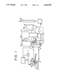
FIG. 1 is a simplified schematic diagram of one embodiment of the invention carried out in conjunction with the incineration of hazardous waste.
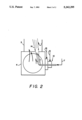
FIG. 2 is a more detailed view of the embodiment illustrated in FIG. 1 showing in greater detail the injection of high velocity oxidant and the aspiration thereinto of exhaust gases.
In the combustion method of this invention combustible material is provided into a first combustion zone. The combustible material or fuel may be in solid, liquid, gaseous or mixed phase form and may be provided into the first combustion zone separately from or with the oxidant for combustion. The invention will have particular utility with combustible material which has a highly variable heating value per unit volume and/or which is supplied into the first combustion zone at a highly variable rate. Examples of combustible material or fuel which may be employed with the combustion method of this invention include coal, wood, lignite, heavy oil, trash, solid and/or liquid waste, aqueous plant effluent and hazardous waste. Typically when the fuel is in solid or liquid form, gaseous fuel will volatize from the solid or liquid.
The oxidant employed in the first combustion zone may be air, oxygen-enriched air and/or technically pure oxygen and may be supplied with the combustible material such as through a burner or as a separate oxidant stream such as through a lance. Air may also pass into the first combustion zone by infiltration.
Within the first combustion zone the combustible material is combusted to produce gaseous exhaust which comprises products of complete combustion, such as carbon dioxide and water vapor, and also products of incomplete combustion. A product of incomplete combustion or PIC may be defined as a species which can undergo oxidation or further oxidation under combustion zone conditions of temperature and pressure. Examples of well known PICs include carbon monoxide, hydrocarbons, soot and chlorinated hydrocarbons such as dioxins and furans.
The gaseous exhaust is then passed from the first combustion zone into a second combustion zone which may be integral with the first combustion zone or may be separate from the first combustion zone and connected therewith by a conduit or other passageway. In the incineration of hazardous waste the first combustion zone may be the primary combustion chamber of an incineration system and the second combustion zone may be the secondary combustion chamber of such a system. Frequently the primary combustion chamber of an incineration system comprises a rotary kiln. The primary combustion chamber is often used for handling solid or sludge waste while the secondary combustion chamber is used to treat the gaseous exhaust from the primary combustion chamber to ensure good destruction of the waste by operating at a higher temperature and providing sufficient gas residence time to ensure the destruction of the waste.
At least one high velocity oxidant stream having an oxygen concentration of at least 25 percent, and preferably at least 30 percent, is injected into the second combustion zone. Most preferably the high velocity oxidant is technically pure oxygen having an oxygen concentration of 99.5 percent or more. Typically the high velocity oxidant will have a velocity of at least 300 feet per second and generally the velocity will be within the range of from 400 to 1500 feet per second. The velocity is sufficiently high to cause exhaust gases to aspirate into the oxidant. The aspiration may occur within the second combustion zone and/or may occur upstream of the second combustion zone. The aspiration enables the exhaust gas and in particular the PICs within the exhaust gas to intimately mix with the oxidant resulting in the subsequent combustion being stable with the avoidance of hot spots which would favor NOx formation and would cause refractory damage. Moreover the products of complete combustion from the combustion reaction, e.g. carbon dioxide and water vapor, within the exhaust gas which are also aspirated into the high velocity oxidant serve as ballast for the combustion reaction whereby the combustion reaction is spread out and heat from the combustion reaction is absorbed by this heat sink. This further inhibits NOx formation.
After aspiration of exhaust gas into the high velocity oxidant, products of incomplete combustion combust with the oxidant within the second combustion zone. If desired, additional fuel and/or oxidant may be provided into the second combustion zone to carry out combustion.
The high velocity oxidant is injected into the second combustion zone in a manner such that there is no impingement of the oxidant jet on the walls of the second combustion zone within about 300 oxidant jet diameters from the high velocity oxidant injection point. Preferably the high velocity oxidant is injected into the second combustion zone with an orientation substantially parallel to the axial direction of the second combustion zone. In this way local overheating which may cause refractory damage as well as excessive NOx generation is avoided.
Preferably the high velocity oxidant is injected into the second combustion zone in a plurality of streams. Generally the number of high velocity oxidant streams will be within the range of from 30 to 50. The plurality of high velocity oxidant streams may be injected parallel to each other. However, since neighboring parallel streams would generally immediately merge into a single jet, it is preferred that at least two, and preferably most of the plurality of high velocity oxidant streams be injected as outwardly diverging streams. In a particularly preferred embodiment, the outwardly diverging streams in close proximity converge after aspiration of PICs-containing exhaust gas into the oxidant. The use of a plurality of streams improves the overall aspiration of exhaust gas into the oxidant and the use of outwardly diverging oxidant streams further improves the completeness of the aspiration, thus serving to ensure that PICs do not bypass the flame zone in the second combustion zone while further retarding NOx formation. The downstream convergence of the outwardly divergent streams bring the PICs together with the oxidant in a manner which improves the complete combustion of these species within the second combustion zone. It also prevents flame impingement on the furnace or combustion zone walls so as to avoid overheating of refractory or slagging.
A preferred embodiment of this invention involves the injection of the oxidant through a plurality of orifices as a cluster, such as on a nozzle, such that the farther away from the center of the cluster, the greater is the divergent angle of the orifice. This embodiment has the advantage of promoting staged combustion thus further reducing flame temperature and NOx formation.
In order to further improve the temperature control of the combustion carried out within the second combustion zone, atomized water or another coolant may be provided into the second combustion zone. When such auxiliary coolant is employed, it is preferred that it be provided in such manner that it also is aspirated into the high velocity oxidant either prior to combustion or during the combustion.
In thee practice of this invention, it is sometimes preferred that the first combustion zone be operated under pyrolytic or fuel-rich conditions. Fuel-rich conditions within the first combustion reduce the gas volumetric flow within the first combustion zone, thus reducing the particulate carryover to the second combustion zone. Moreover, fuel-rich conditions within the first combustion zone could lead to a more stable temperature and thus to a more stable generation of combustible vapors which reduces the fluctuation of oxygen demand while significantly reducing the fuel requirement in the second combustion zone. As a result a higher throughput can be achieved.
It is often thought that in a fuel-rich combustion zone the formation of NOx would be necessarily low. However, this is not generally true in a mixing-limited combustion process (as opposed to premixed combustion). The problem is that at the local interface of fuel and oxidant, there is often still sufficient excess oxygen and high temperature to generate NOx at significant rates. With the use of a small-diameter high-velocity oxidant jet, preferably wherein the velocity of oxidant jet exceeds the blow-off velocity, fuel containing furnace gas is being rapidly aspirated into the jet. Therefore, the fuel/oxygen ratio is quickly increased beyond the stoichiometric ratio and the equilibrium flame temperature of the mixture is quickly reduced due to the entrainment of excess fuel and combustion products. Meanwhile the initial jet velocity is too high for combustion to take place. As a result, the gas residence time at conditions suitable for NOx generation (i.e. high temperature, excess oxygen) is too short for any significant generation of NOx. Furthermore, the aspiration effect of the high velocity jet creates intense mixing and strong recirculation of the furnace gas. This minimizes the probability of local excess oxygen.
The intensive mixing of the furnace gas in a fuel-rich combustion zone promotes the gasification of the organic materials to form gaseous fuels, such as carbon monoxide, hydrogen and methane, while it minimizes the formation of soot particles. Soot particles are a source of PICs and may be difficult to burn out in the secondary combustion zone once they are formed. Depending on the amount of oxygen available, at a sufficiently high temperature, volatiles would undergo chemical reactions including pyrolysis (thermal cracking), partial oxidation (also known as oxidative pyrolysis) or complete oxidation. If the local oxygen/carbon ratio is low and/or the free radical concentrations are low, heavy hydrocarbons (soot) are formed through polymerization (recombination) reactions. With the use of high velocity jets to enhance the mixing and recirculation of the gas stream, a more uniform profile of local oxygen/carbon ratios is obtained.
Oxygen can be supplied not only by oxygen molecules but also by steam and carbon dioxide. Internal recirculation within the combustion zone caused by the high velocity oxidant enables stream and/or carbon dioxide generated by the drying or combustion of material within the combustion zone, such as solid waste, to be beneficially used for soot reduction. In addition, the vigorous mixing and recirculation within the combustion zone distributes free radicals uniformly throughout the combustion zone thus helping to further reduce the formation of soot.
The preferred method of the invention is to use multiple streams of jets so that smaller diameter jets can be used. Preferably, the diameter of each jet is less than 1/100 of the diameter or width of the combustion chamber or zone The smaller the diameter, the quicker the aspiration takes place and the smaller is the turbulence scale. A particularly preferred embodiment of the invention is the use of the multiple-stream, divergent-converging configuration described earlier. The luminous flame size is increased due to this divergent-converging configuration compared to a single stream flame, leading to greater radiative heat transfer to the heat load. The velocity of the high velocity jet or jets will generally be within the range of from 400 to 1500 feet per second.
In the practice of this invention, it is preferred that the second combustion zone be operated under oxidative or oxygen-rich conditions. This ensures that all combustibles are completely combusted so that undesired emissions to the atmosphere are eliminated. The injection rate and duration of the high velocity oxidant injected into the second combustion zone may be increased or decreased in order to maintain the desired level of excess oxygen within the second combustions zone. The primary way of maintaining the desired level of excess oxygen within the second combustion zone is to monitor the oxygen concentration within the second combustion zone or within the effluent from the second combustion zone and adjust the high velocity oxidant flow accordingly. A preferred supplemental method of maintaining a sufficient level of excess oxygen within the second combustion zone is to monitor the carbon monoxide concentration within the second combustion zone or within the effluent and to increase the oxygen concentration set point or increase the oxidant flow accordingly. Other parameters of the effluent which may be monitored to maintain the desired oxidative conditions within the second combustion zone include opacity and luminosity.
The following Example is provided to further illustrate the invention and the benefits attainable thereby. The Example is not intended to be limiting.
The invention was carried out in conjunction with the incineration of hazardous waste employing a system such as illustrated in FIGS. 1 and 2. The numerals in the Figures are the same for the common elements.
Referring now to the Figures, hazardous waste comprising oily sludge and contaminated soil was provided at a rate of 4.1 tons per hour through input means 1 into rotary kiln 2 which was the first combustion zone of the invention. Natural gas 17 and air 18 were provided into kiln 2 through burner 3 and oxygen 19 was provided into kiln 2 through lance 20. The hazardous waste was combusted under pyrolytic conditions to produce exhaust gas which included products of incomplete combustion. In this case the PICs comprised carbon monoxide, methane and other unknown organic components. The oxygen flow into the rotary kiln was adjusted to maintain the kiln 2 exit temperature near the desired level which ensured the removal of hazardous waste from the ash without overheating the ash.
The gaseous exhaust was passed from kiln 2 into transition chamber 4 and from there into secondary combustion chamber 5. Chambers 4 and 5 are the second combustion zone of this invention. In proximity to the flow of the gaseous exhaust through transition chamber 4 there was injected through lance 6 technically pure oxygen 7 in over 30 diverging streams 8 at a velocity of up to 1500 feet per second toward and into secondary combustion chamber 5. All of the high velocity oxidant streams 8 converged into combined jet 14. A small amount of natural gas 15 and air 16 were also supplied through a burner 10 to assist the combustion within chamber 4. Atomized water spray 9 was also supplied into chamber 4. The gaseous exhaust and the atomized water were aspirated into the high velocity oxidant streams and combustion was carried out in transition chamber 4 and in secondary combustion chamber 5. Oxidative conditions were maintained throughout the combustion in chamber 5 by monitoring the oxygen concentration of the flue gas at the exit of chamber 5 as a process variable. The process variable was compared with a desired set point to determine the desired flowrate of oxygen using a proportional-integral-derivative (PID) controller as indicated by line 21 and the oxygen flow rate was increased whenever the oxygen level in the effluent fell below a predetermined level. In addition the desired oxygen flow rate was increased whenever the carbon monoxide level in the flue gas exceeded 20 ppm.
Exhaust or effluent from chamber 5 was passed through spray tower 11 and baghouse 12 and then exhausted to the atmosphere through stack 13. There were no appreciable levels of carbon monoxide in the exhaust gases passing up stack 13 thus indicating that all PICs were completely combusted. Minimal soot formation was observed in the combustion process. Moreover the NOx level was well within acceptable levels.
For comparative purposes a procedure similar to that described above was carried out except the injection of high velocity oxidant into the second combustion zone was not employed. The processing rate for hazardous waste could not exceed 2.5 tons per hour without the frequent excursions of significant levels of carbon monoxide in the effluent released to the atmosphere.
Although the invention has been described in detail with reference to certain embodiments, those skilled in the art will recognize that there are other embodiments within the spirit and scope of the claims.
Claims (8)
1. A method for operating a pyrolytic combustion zone for simultaneously controlling the generation of both nitrogen oxides and products of incomplete combustion comprising:
(A) injecting into a combustion zone operation under fuel-rich conditions and containing furnace gases including fuel at least one jet of oxidant at an initial high velocity sufficient to entrain furnace gases including fuel into the jet, said initial high velocity being too high for combustion to take place;
(B) increasing the fuel to oxygen ratio within the jet to exceed the stoichiometric ratio while causing intense mixing of the fuel and oxidant in the combustion zone due to the high velocity jet; and thereafter
(C) combusting fuel and oxidant in the combustion zone while maintaining the level of nitrogen oxides generation low because of the high fuel to oxygen ratio and while generating products of incomplete combustion because of the high fuel to oxygen ratio but limiting the amount of soot produced because of the intense mixing of fuel and oxidant.
2. The method of claim 1 wherein a plurality of high velocity oxidant jets is employed.
3. The method of claim 2 wherein at least two high velocity oxidant jets are injected into the combustion zone in a diverging orientation and subsequently converge downstream in the combustion zone.
4. The method of claim 1 wherein the velocity of the oxidant jet(s) exceeds the blow-off velocity.
5. The method of claim 1 wherein the high velocity oxidant jet(s) cause recirculation to occur within the combustion zone.
6. The method of claim 5 wherein at least one of steam and carbon dioxide within the combustion zone are brought to the combustion by the internal recirculation and serve to provide oxygen to the combustion.
7. The method of claim 1 further comprising passing products of incomplete combustion into a second combustion zone and combusting them therein.
8. The method of claim 7 further comprising injecting at least one stream of oxidant having an oxygen concentration of at least 25 percent into the second combustion zone at a high velocity sufficient to aspirate products of incomplete combustion into the high velocity oxidant stream(s) and combusting products of incomplete combustion with high velocity oxidant within the second combustion zone.
Priority Applications (1)
| Application Number | Priority Date | Filing Date | Title |
|---|---|---|---|
| US07/970,881 US5242295A (en) | 1991-02-11 | 1992-11-03 | Combustion method for simultaneous control of nitrogen oxides and products of incomplete combustion |
Applications Claiming Priority (3)
| Application Number | Priority Date | Filing Date | Title |
|---|---|---|---|
| US65337091A | 1991-02-11 | 1991-02-11 | |
| US07/830,774 US5213492A (en) | 1991-02-11 | 1992-02-06 | Combustion method for simultaneous control of nitrogen oxides and products of incomplete combustion |
| US07/970,881 US5242295A (en) | 1991-02-11 | 1992-11-03 | Combustion method for simultaneous control of nitrogen oxides and products of incomplete combustion |
Related Parent Applications (1)
| Application Number | Title | Priority Date | Filing Date |
|---|---|---|---|
| US07/830,774 Division US5213492A (en) | 1991-02-11 | 1992-02-06 | Combustion method for simultaneous control of nitrogen oxides and products of incomplete combustion |
Publications (1)
| Publication Number | Publication Date |
|---|---|
| US5242295A true US5242295A (en) | 1993-09-07 |
Family
ID=27417896
Family Applications (1)
| Application Number | Title | Priority Date | Filing Date |
|---|---|---|---|
| US07/970,881 Expired - Lifetime US5242295A (en) | 1991-02-11 | 1992-11-03 | Combustion method for simultaneous control of nitrogen oxides and products of incomplete combustion |
Country Status (1)
| Country | Link |
|---|---|
| US (1) | US5242295A (en) |
Cited By (10)
| Publication number | Priority date | Publication date | Assignee | Title |
|---|---|---|---|---|
| US5315941A (en) * | 1993-06-07 | 1994-05-31 | The Babcock & Wilcox Company | Method and apparatus for injecting nox inhibiting reagent into the flue gas of a boiler |
| US5495813A (en) * | 1992-11-18 | 1996-03-05 | The Boc Group Pcl | Combustion method and apparatus |
| EP0738856A2 (en) * | 1995-03-30 | 1996-10-23 | Müllkraftwerk Schwandorf Betriebsgesellschaft mbH | Method and device for the combustion of solid fuels |
| EP0773406A2 (en) | 1995-11-08 | 1997-05-14 | Process Combustion Corporation | Method to minimize chemically bound NOx in a combustion process |
| US5993203A (en) * | 1995-11-01 | 1999-11-30 | Gas Research Institute | Heat transfer enhancements for increasing fuel efficiency in high temperature furnaces |
| US6481998B2 (en) | 1995-06-07 | 2002-11-19 | Ge Energy And Environmental Research Corporation | High velocity reburn fuel injector |
| US20030175631A1 (en) * | 2000-10-12 | 2003-09-18 | Asahi Glass Company Limited | Method for reducing nitrogen oxides in combustion gas from combustion furnace |
| US20090263752A1 (en) * | 2008-04-22 | 2009-10-22 | Aga Ab | Method and device for combustion of solid phase fuel |
| GB2531010A (en) * | 2014-10-07 | 2016-04-13 | Linde Ag | Incineration of waste |
| US11148504B2 (en) * | 2016-11-29 | 2021-10-19 | Webasto SE | Fuel-operated vehicle heating device and method to operating a fuel-operated vehicle heating device |
Citations (24)
| Publication number | Priority date | Publication date | Assignee | Title |
|---|---|---|---|---|
| US3355254A (en) * | 1966-04-26 | 1967-11-28 | Cornell Hoskinson Mfg | Waste products combustion apparatus |
| US3547056A (en) * | 1969-05-14 | 1970-12-15 | Little Inc A | Incinerator system |
| US3601069A (en) * | 1969-09-25 | 1971-08-24 | Thomas P Mancuso | Incinerator |
| US3792671A (en) * | 1972-05-17 | 1974-02-19 | Clean Air Ator Corp | Incinerator with afterburner |
| US4078503A (en) * | 1976-07-19 | 1978-03-14 | Nichols Engineering & Research Corporation | Method and apparatus for treating off-gas from a furnace for burning organic material in an oxygen deficient atmosphere |
| US4167909A (en) * | 1976-12-09 | 1979-09-18 | Dauvergne Hector A | Solid fuel burner |
| GB2064735A (en) * | 1979-12-01 | 1981-06-17 | Bruun & Soerensen | Incineration process and plant |
| US4279208A (en) * | 1978-12-04 | 1981-07-21 | L'air Liquide, Societe Anonyme Pour L'etude Et L'exploitation Des Procedes Georges Claude | Method and apparatus for heat treatment of industrial wastes |
| US4329932A (en) * | 1979-06-07 | 1982-05-18 | Mitsubishi Jukogyo Kabushiki Kaisha | Method of burning fuel with lowered nitrogen-oxides emission |
| US4378205A (en) * | 1980-04-10 | 1983-03-29 | Union Carbide Corporation | Oxygen aspirator burner and process for firing a furnace |
| US4408982A (en) * | 1982-01-05 | 1983-10-11 | Union Carbide Corporation | Process for firing a furnace |
| US4474121A (en) * | 1981-12-21 | 1984-10-02 | Sterling Drug Inc. | Furnace control method |
| US4541796A (en) * | 1980-04-10 | 1985-09-17 | Union Carbide Corporation | Oxygen aspirator burner for firing a furnace |
| US4861262A (en) * | 1984-08-17 | 1989-08-29 | American Combustion, Inc. | Method and apparatus for waste disposal |
| US4863371A (en) * | 1988-06-03 | 1989-09-05 | Union Carbide Corporation | Low NOx high efficiency combustion process |
| US4878829A (en) * | 1988-05-05 | 1989-11-07 | Union Carbide Corporation | Fuel jet burner and combustion method |
| US4907961A (en) * | 1988-05-05 | 1990-03-13 | Union Carbide Corporation | Oxygen jet burner and combustion method |
| US4922841A (en) * | 1988-09-14 | 1990-05-08 | Kent John M | Method and apparatus for using hazardous waste to form non-hazardous aggregate |
| US4946382A (en) * | 1989-05-23 | 1990-08-07 | Union Carbide Corporation | Method for combusting fuel containing bound nitrogen |
| US4957050A (en) * | 1989-09-05 | 1990-09-18 | Union Carbide Corporation | Combustion process having improved temperature distribution |
| US4969814A (en) * | 1989-05-08 | 1990-11-13 | Union Carbide Corporation | Multiple oxidant jet combustion method and apparatus |
| US4973346A (en) * | 1989-10-30 | 1990-11-27 | Union Carbide Corporation | Glassmelting method with reduced nox generation |
| EP0426471A2 (en) * | 1989-11-02 | 1991-05-08 | Entech, Inc. | Municipal waste thermal oxidation system |
| US5014680A (en) * | 1989-03-15 | 1991-05-14 | The United States Of America As Represented By The United States Department Of Energy | Self-powered automatic secondary air controllers for woodstoves and small furnaces |
-
1992
- 1992-11-03 US US07/970,881 patent/US5242295A/en not_active Expired - Lifetime
Patent Citations (24)
| Publication number | Priority date | Publication date | Assignee | Title |
|---|---|---|---|---|
| US3355254A (en) * | 1966-04-26 | 1967-11-28 | Cornell Hoskinson Mfg | Waste products combustion apparatus |
| US3547056A (en) * | 1969-05-14 | 1970-12-15 | Little Inc A | Incinerator system |
| US3601069A (en) * | 1969-09-25 | 1971-08-24 | Thomas P Mancuso | Incinerator |
| US3792671A (en) * | 1972-05-17 | 1974-02-19 | Clean Air Ator Corp | Incinerator with afterburner |
| US4078503A (en) * | 1976-07-19 | 1978-03-14 | Nichols Engineering & Research Corporation | Method and apparatus for treating off-gas from a furnace for burning organic material in an oxygen deficient atmosphere |
| US4167909A (en) * | 1976-12-09 | 1979-09-18 | Dauvergne Hector A | Solid fuel burner |
| US4279208A (en) * | 1978-12-04 | 1981-07-21 | L'air Liquide, Societe Anonyme Pour L'etude Et L'exploitation Des Procedes Georges Claude | Method and apparatus for heat treatment of industrial wastes |
| US4329932A (en) * | 1979-06-07 | 1982-05-18 | Mitsubishi Jukogyo Kabushiki Kaisha | Method of burning fuel with lowered nitrogen-oxides emission |
| GB2064735A (en) * | 1979-12-01 | 1981-06-17 | Bruun & Soerensen | Incineration process and plant |
| US4541796A (en) * | 1980-04-10 | 1985-09-17 | Union Carbide Corporation | Oxygen aspirator burner for firing a furnace |
| US4378205A (en) * | 1980-04-10 | 1983-03-29 | Union Carbide Corporation | Oxygen aspirator burner and process for firing a furnace |
| US4474121A (en) * | 1981-12-21 | 1984-10-02 | Sterling Drug Inc. | Furnace control method |
| US4408982A (en) * | 1982-01-05 | 1983-10-11 | Union Carbide Corporation | Process for firing a furnace |
| US4861262A (en) * | 1984-08-17 | 1989-08-29 | American Combustion, Inc. | Method and apparatus for waste disposal |
| US4907961A (en) * | 1988-05-05 | 1990-03-13 | Union Carbide Corporation | Oxygen jet burner and combustion method |
| US4878829A (en) * | 1988-05-05 | 1989-11-07 | Union Carbide Corporation | Fuel jet burner and combustion method |
| US4863371A (en) * | 1988-06-03 | 1989-09-05 | Union Carbide Corporation | Low NOx high efficiency combustion process |
| US4922841A (en) * | 1988-09-14 | 1990-05-08 | Kent John M | Method and apparatus for using hazardous waste to form non-hazardous aggregate |
| US5014680A (en) * | 1989-03-15 | 1991-05-14 | The United States Of America As Represented By The United States Department Of Energy | Self-powered automatic secondary air controllers for woodstoves and small furnaces |
| US4969814A (en) * | 1989-05-08 | 1990-11-13 | Union Carbide Corporation | Multiple oxidant jet combustion method and apparatus |
| US4946382A (en) * | 1989-05-23 | 1990-08-07 | Union Carbide Corporation | Method for combusting fuel containing bound nitrogen |
| US4957050A (en) * | 1989-09-05 | 1990-09-18 | Union Carbide Corporation | Combustion process having improved temperature distribution |
| US4973346A (en) * | 1989-10-30 | 1990-11-27 | Union Carbide Corporation | Glassmelting method with reduced nox generation |
| EP0426471A2 (en) * | 1989-11-02 | 1991-05-08 | Entech, Inc. | Municipal waste thermal oxidation system |
Cited By (14)
| Publication number | Priority date | Publication date | Assignee | Title |
|---|---|---|---|---|
| US5495813A (en) * | 1992-11-18 | 1996-03-05 | The Boc Group Pcl | Combustion method and apparatus |
| US5315941A (en) * | 1993-06-07 | 1994-05-31 | The Babcock & Wilcox Company | Method and apparatus for injecting nox inhibiting reagent into the flue gas of a boiler |
| EP0738856A2 (en) * | 1995-03-30 | 1996-10-23 | Müllkraftwerk Schwandorf Betriebsgesellschaft mbH | Method and device for the combustion of solid fuels |
| EP0738856A3 (en) * | 1995-03-30 | 1998-07-15 | Müllkraftwerk Schwandorf Betriebsgesellschaft mbH | Method and device for the combustion of solid fuels |
| US6481998B2 (en) | 1995-06-07 | 2002-11-19 | Ge Energy And Environmental Research Corporation | High velocity reburn fuel injector |
| US5993203A (en) * | 1995-11-01 | 1999-11-30 | Gas Research Institute | Heat transfer enhancements for increasing fuel efficiency in high temperature furnaces |
| EP0773406A2 (en) | 1995-11-08 | 1997-05-14 | Process Combustion Corporation | Method to minimize chemically bound NOx in a combustion process |
| US5707596A (en) * | 1995-11-08 | 1998-01-13 | Process Combustion Corporation | Method to minimize chemically bound nox in a combustion process |
| US20030175631A1 (en) * | 2000-10-12 | 2003-09-18 | Asahi Glass Company Limited | Method for reducing nitrogen oxides in combustion gas from combustion furnace |
| US6939125B2 (en) * | 2000-10-12 | 2005-09-06 | Asahi Glass Company, Limited | Method for reducing nitrogen oxides in combustion gas from combustion furnace |
| US20090263752A1 (en) * | 2008-04-22 | 2009-10-22 | Aga Ab | Method and device for combustion of solid phase fuel |
| US8382468B2 (en) * | 2008-04-22 | 2013-02-26 | Aga Ab | Method and device for combustion of solid phase fuel |
| GB2531010A (en) * | 2014-10-07 | 2016-04-13 | Linde Ag | Incineration of waste |
| US11148504B2 (en) * | 2016-11-29 | 2021-10-19 | Webasto SE | Fuel-operated vehicle heating device and method to operating a fuel-operated vehicle heating device |
Similar Documents
| Publication | Publication Date | Title |
|---|---|---|
| EP0344784B1 (en) | Low nox high efficiency combustion process | |
| EP0541105B1 (en) | Recirculation and plug flow combustion method | |
| US5213492A (en) | Combustion method for simultaneous control of nitrogen oxides and products of incomplete combustion | |
| EP0397088B1 (en) | Multiple oxidant jet combustion method and apparatus | |
| US20090136406A1 (en) | Flameless thermal oxidation method | |
| US5123364A (en) | Method and apparatus for co-processing hazardous wastes | |
| KR100252332B1 (en) | Method for deeply staged combustion | |
| EP0509193B1 (en) | Fluid waste burner system | |
| US6244200B1 (en) | Low NOx pulverized solid fuel combustion process and apparatus | |
| US5242295A (en) | Combustion method for simultaneous control of nitrogen oxides and products of incomplete combustion | |
| EP0451648B1 (en) | Opposed fired rotary kiln | |
| EP0434056A1 (en) | Method for combusting wet waste | |
| US5102330A (en) | Opposed fired rotary kiln | |
| EP0663564B1 (en) | Combustion method for simultaneous control of nitrogen oxides and products of incomplete combustion | |
| WO2013133290A1 (en) | Grate-type waste incinerator and method for incinerating waste | |
| US5216968A (en) | Method of stabilizing a combustion process | |
| EP1071912B1 (en) | Method and apparatus for the prevention of global warming, through elimination of hazardous exhaust gases of waste and/or fuel burners | |
| EP1500875A1 (en) | Method of operating waste incinerator and waste incinerator | |
| JP3014953B2 (en) | Incinerator | |
| JPH0650507A (en) | Boiler device | |
| JPH10220720A (en) | Low nox combustion method in incineration furnace | |
| RU2027104C1 (en) | Method and device for low-temperature burning of gas | |
| JP2002005422A (en) | Combustion method of combustion melting furnace and combustion melting furnace | |
| MX2008002067A (en) | Methods and systems for removing mercury from combustion flue gas. | |
| EP0419463A1 (en) | A method for waste disposal |
Legal Events
| Date | Code | Title | Description |
|---|---|---|---|
| STCF | Information on status: patent grant |
Free format text: PATENTED CASE |
|
| CC | Certificate of correction | ||
| FPAY | Fee payment |
Year of fee payment: 4 |
|
| FPAY | Fee payment |
Year of fee payment: 8 |
|
| FPAY | Fee payment |
Year of fee payment: 12 |