US5243656A - Audio circuit - Google Patents
Audio circuit Download PDFInfo
- Publication number
- US5243656A US5243656A US07/814,823 US81482391A US5243656A US 5243656 A US5243656 A US 5243656A US 81482391 A US81482391 A US 81482391A US 5243656 A US5243656 A US 5243656A
- Authority
- US
- United States
- Prior art keywords
- input signal
- amplifier
- power source
- receiving
- amplifiers
- Prior art date
- Legal status (The legal status is an assumption and is not a legal conclusion. Google has not performed a legal analysis and makes no representation as to the accuracy of the status listed.)
- Expired - Fee Related
Links
Images


Classifications
-
- H—ELECTRICITY
- H04—ELECTRIC COMMUNICATION TECHNIQUE
- H04R—LOUDSPEAKERS, MICROPHONES, GRAMOPHONE PICK-UPS OR LIKE ACOUSTIC ELECTROMECHANICAL TRANSDUCERS; DEAF-AID SETS; PUBLIC ADDRESS SYSTEMS
- H04R5/00—Stereophonic arrangements
- H04R5/04—Circuit arrangements, e.g. for selective connection of amplifier inputs/outputs to loudspeakers, for loudspeaker detection, or for adaptation of settings to personal preferences or hearing impairments
Definitions
- the present invention relates generally to an audio circuit. Particularly, the present invention relates to an audio circuit applicable at an output stage for multi-channel systems.
- an audio circuit comprising: amplification means, including a plurality of amplifiers respectively receiving a corresponding input signal from a signal source, at least one of the amplifiers being an inverted amplifier for inverting at least one of the signals; and a plurality of transducing means respectively corresponding to each amplifier for receiving signals output from the amplifiers for converting the signals into vibratory energy, a transducing means corresponding to the inverted amplifier being connected at a polarity opposite that of the other transducing means.
- a multi-channel audio circuit comprising: filtering means for providing selected frequencies for a left input signal, a right input signal and a combined left and right input signal; amplification means, including a left amplifier for receiving the left input signal, a right amplifier for receiving the right input signal, one of the left or right amplifiers being an inverted amplifier for inverting at least one of the left or right input signals; and a plurality of transducing means respectively receiving the left input signal, the right input signal, and a combination of both of the left and right input signals, a polarity of the transducing means receiving the inverted left or right signal being opposite a polarity of the transducing means receiving the non-inverted left or right signal.
- a 3-D multi-channel audio system comprising: a power source; means for producing left and right stereo input signals; filtering means for providing selected frequencies for a left input signal, a right input signal and a combined left and right input signal; amplification means, including, a left amplifier for receiving the left input signal, a right amplifier for receiving the right input signal, one of the left or right amplifiers being an inverted amplifier for inverting at least one of the left or right input signals; power amplifiers for each of the left, right, and combined left and right input signals, respectively; and a plurality of transducing means respectively receiving the left input signal, the right input signal, and a combination of both of the left and right input signals, a polarity of the transducing means receiving the inverted left or right signal being opposite a polarity of a transducing means receiving the non-inverted left or right signal.
- FIG. 1 is a block diagram of an audio system according to the present invention.
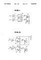
- FIG. 2 is a circuit diagram of a second embodiment of an audio circuit according to the invention.
- FIGS. 3a-3c is a graph showing an input audio signal in relation to a convention al power source current strength and a power source current strength according to the invention.
- FIG. 4 is circuit diagram of a third embodiment of an audio circuit according to the present invention.
- FIG. 5 is a block diagram of a 3-D audio system according to the present invention.
- FIG. 1 is a circuit diagram of a first embodiment according to the present invention. This embodiment is applied to a two channel audio circuit.
- the circuit consists of a signal amplifier 1, an inverted signal amplifier 2, power amplifiers 3, 4 speakers 5, 6 and condensers C 1 and C 2 .
- One input channel, I N1 is connected to the gain amplifier 1 and fed to power amplifier 3.
- the power amplifier 3 is connected through condenser C 1 to the positive (+) terminal of the speaker 5.
- the other input channel, IN 2 is connected through the inverted amplifier 2 to the other power amplifier 4.
- the output of the power amplifier 4 is fed through condensor C 2 to the negative (-) terminal of the speaker 6.
- the (-) terminal of speaker 5 and the (+) terminal of speaker 6 are connected to ground. It will be noted that the polarities of speakers 5 and 6 are reversed.
- IN 1 and IN 2 combine to provide stereo reproduction of the source material. Additionally, since low frequency sounds are often nearly identical for both left and right channels, a third amplifier may be implemented for only the low frequencies of both left and right channels to form the basis for a 3-D sound system as will be explained in detail hereinlater.
- FIG. 2 shows a second embodiment of an audio circuit according to the present invention.
- each power amplifier of a 2 channel audio system is arranged with a push-pull circuit.
- the audio circuit of this embodiment comprises a signal amplifier 1, an inverted signal amplifier 2, power amplifiers 3 and 4, speakers 5, 6, power source 7 and condensers C 1 and C 2 .
- an npn transistor Tr1 and a pnp transistor Tr2 are connected in series. The bases of each transistor are connected to the output of amplifier 1 and the collector of Tr1 is connected to the positive terminal of the power source 7 while the collector of Tr2 is connected to ground.
- Each emitter is connected commonly through the condenser C 1 to the positive terminal of the speaker 5.
- transistors Tr3 (npn) and Tr4 (pnp) are connected in series between the positive pole of the power source 7 and ground, while the bases of both Tr3 and Tr4 are connected to the output of inverted power amplifier 2.
- the collector of Tr3 is connected to the positive terminal of the power source 7 while the collector of Tr4 is connected to ground.
- the emitters of Tr3 and Tr4 are commonly connected to the negative (-) terminal of the speaker 6 via the condenser C 2 . Meanwhile, the negative terminal of speaker 5 and the positive terminal of speaker 6 are connected to ground.
- the transistor Tr1 of power amplifier 3 is ON in the positive half and OFF in the negative half of each cycle.
- Tr2 is OFF in the positive half and ON in the negative half of each cycle. Therefore, during the positive half of each cycle the connection arrangement is as follows: power source 7>Tr1>C 1 >speaker 5>ground, thereby storing a charge in C 1 .
- the charge from C 1 is discharged through a loop arranged as follows: Tr2>ground>speaker 5>back to C 1 .
- the power amplifier 4, receiving IN2 is set up reciprocally to the above.
- Tr3 since the signal IN2 is inverted by the inverting amplifier 2 and in a case where the cyclic frequency of IN2 is identical to IN1, during a positive half cycle of IN2, Tr3 will be OFF, Tr4 will be ON and during a negative cycle of IN2, Tr3 will be ON and Tr4 will be OFF. Therefore, during a positive half cycle of IN2, current from the power source 7 will not flow while during a negative half cycle, current will flow.
- the input signal frequencies are reciprocal at every half cycle ripple caused at the the power source 7 will be considerably reduced, as will the maximum power expenditure required.
- a power transformer for powering an apparatus utilizing the arrangement of the invention may be made smaller and lighter and may be produced at lower cost.
- FIG. 3 shows (a) an input signal, (b) a current signal from a power source of an audio circuit according to the prior art and, (c) a current signal from a power source for an apparatus utilizing the circuit of the invention.
- a current signal according to the conventional art will display 0.4 A peak-to-peak ripple.
- a peak-to-peak ripple of only 0.15 A is incurred, less than half that of conventional arrangements.
- FIG. 4 shows a third embodiment of a circuit according to the present invention.
- the above-described second embodiment is applicable to a single power source apparatus
- the third embodiment is adapted to a device utilizing double power sources, otherwise the numbering of components will be the same and description of like parts of the previous embodiments will be omitted for brevity.
- condensers C 1 and C 2 utilized in the second embodiment, are not required.
- the emitters of Tr1 and Tr2 are connected directly to the positive (+) terminal of speaker 5 whereas the emitters of Tr3 and Tr4 are connected directly to the negative (-) terminal of speaker 6.
- the collectors of Tr1 and Tr3 are connected to the positive pole of a positive power source 7a, while the collectors of Tr2 and Tr4 are to the negative pole of a negative power source 7b.
- the negative pole of the positive power source 7a is connected to ground via the positive pole of the negative power source 7b, otherwise the arrangement is the same as that of the second embodiment.
- each power source 7a and 7b always supplies power to one of the power amplifiers 3 and 4 and further, according to the above construction, a size of each of the power sources 7a and 7b can be significantly reduced.
- signal amplifiers 1 and 2 power amplifiers 3 and 4, and speakers 5 and 6 are identical to the previous embodiment and will not be explained again in detail.
- the present embodiment namely at the input stage, before the left (L) and right (R) channel signals are input into the amplifier 1 and the inverted amplifier 2, they are passed through high-pass filters 7 and 8 through which middle and high frequencies, for example, are passed.
- a third signal comprised of both L and R signals combined, is passed through a low-pass filter 9 to allow bass frequencies, for example, to pass to a third power amplifier 10 and therethrough to a third speaker 11.
- power source ripple can be significantly reduced and utilization of the circuit of the invention further allows smaller power sources to be employed. This reduces manufacturing costs and increases design flexibility.
Abstract
Description
Claims (13)
Applications Claiming Priority (2)
| Application Number | Priority Date | Filing Date | Title |
|---|---|---|---|
| JP3-000779 | 1991-01-09 | ||
| JP3000779A JPH04250710A (en) | 1991-01-09 | 1991-01-09 | Audio circuit |
Publications (1)
| Publication Number | Publication Date |
|---|---|
| US5243656A true US5243656A (en) | 1993-09-07 |
Family
ID=11483188
Family Applications (1)
| Application Number | Title | Priority Date | Filing Date |
|---|---|---|---|
| US07/814,823 Expired - Fee Related US5243656A (en) | 1991-01-09 | 1991-12-31 | Audio circuit |
Country Status (2)
| Country | Link |
|---|---|
| US (1) | US5243656A (en) |
| JP (1) | JPH04250710A (en) |
Cited By (12)
| Publication number | Priority date | Publication date | Assignee | Title |
|---|---|---|---|---|
| US5459813A (en) * | 1991-03-27 | 1995-10-17 | R.G.A. & Associates, Ltd | Public address intelligibility system |
| US5469509A (en) * | 1993-12-30 | 1995-11-21 | Monster Cable International, Ltd. | Car audio system with high signal output |
| US6031921A (en) * | 1997-03-25 | 2000-02-29 | Aiwa Co., Ltd. | Loudspeaker unit |
| USD432244S (en) * | 1998-04-20 | 2000-10-17 | Adeza Biomedical Corporation | Device for encasing an assay test strip |
| US6181796B1 (en) * | 1998-02-13 | 2001-01-30 | National Semiconductor Corporation | Method and system which drives left, right, and subwoofer transducers with multichannel amplifier having reduced power supply requirements |
| EP1263130A2 (en) * | 2001-05-17 | 2002-12-04 | Pioneer Corporation | D-class power amplifier with electric power regeneration function |
| US6529787B2 (en) * | 1999-11-15 | 2003-03-04 | Labtec Corporation | Multimedia computer speaker system with bridge-coupled subwoofer |
| US6993480B1 (en) | 1998-11-03 | 2006-01-31 | Srs Labs, Inc. | Voice intelligibility enhancement system |
| US7010131B1 (en) * | 1998-05-15 | 2006-03-07 | Cirrus Logic, Inc. | Quasi-differential power amplifier and method |
| US20070121964A1 (en) * | 2004-01-30 | 2007-05-31 | Thomson Licensing Inc. | First-order loudspeaker crossover network |
| EP1453351A3 (en) * | 2003-02-28 | 2009-01-28 | Yamaha Corporation | Driving system and method of driving loads |
| US8050434B1 (en) | 2006-12-21 | 2011-11-01 | Srs Labs, Inc. | Multi-channel audio enhancement system |
Citations (6)
| Publication number | Priority date | Publication date | Assignee | Title |
|---|---|---|---|---|
| US3394227A (en) * | 1964-12-21 | 1968-07-23 | Philco Ford Corp | Stereophonic power amplifier |
| US4186273A (en) * | 1978-06-05 | 1980-01-29 | Bose Corporation | Stereophonic system having power amplifiers and speakers in a bridge circuit with capacitor connecting junction of speakers to common terminal |
| US4204092A (en) * | 1978-04-11 | 1980-05-20 | Bruney Paul F | Audio image recovery system |
| US4218583A (en) * | 1978-07-28 | 1980-08-19 | Bose Corporation | Varying loudspeaker spatial characteristics |
| GB2074427A (en) * | 1980-03-04 | 1981-10-28 | Clarion Co Ltd | Acoustic apparatus |
| US4837825A (en) * | 1987-02-28 | 1989-06-06 | Shivers Clarence L | Passive ambience recovery system for the reproduction of sound |
-
1991
- 1991-01-09 JP JP3000779A patent/JPH04250710A/en active Pending
- 1991-12-31 US US07/814,823 patent/US5243656A/en not_active Expired - Fee Related
Patent Citations (6)
| Publication number | Priority date | Publication date | Assignee | Title |
|---|---|---|---|---|
| US3394227A (en) * | 1964-12-21 | 1968-07-23 | Philco Ford Corp | Stereophonic power amplifier |
| US4204092A (en) * | 1978-04-11 | 1980-05-20 | Bruney Paul F | Audio image recovery system |
| US4186273A (en) * | 1978-06-05 | 1980-01-29 | Bose Corporation | Stereophonic system having power amplifiers and speakers in a bridge circuit with capacitor connecting junction of speakers to common terminal |
| US4218583A (en) * | 1978-07-28 | 1980-08-19 | Bose Corporation | Varying loudspeaker spatial characteristics |
| GB2074427A (en) * | 1980-03-04 | 1981-10-28 | Clarion Co Ltd | Acoustic apparatus |
| US4837825A (en) * | 1987-02-28 | 1989-06-06 | Shivers Clarence L | Passive ambience recovery system for the reproduction of sound |
Cited By (16)
| Publication number | Priority date | Publication date | Assignee | Title |
|---|---|---|---|---|
| US5459813A (en) * | 1991-03-27 | 1995-10-17 | R.G.A. & Associates, Ltd | Public address intelligibility system |
| US5469509A (en) * | 1993-12-30 | 1995-11-21 | Monster Cable International, Ltd. | Car audio system with high signal output |
| US6031921A (en) * | 1997-03-25 | 2000-02-29 | Aiwa Co., Ltd. | Loudspeaker unit |
| US6181796B1 (en) * | 1998-02-13 | 2001-01-30 | National Semiconductor Corporation | Method and system which drives left, right, and subwoofer transducers with multichannel amplifier having reduced power supply requirements |
| USD432244S (en) * | 1998-04-20 | 2000-10-17 | Adeza Biomedical Corporation | Device for encasing an assay test strip |
| US7010131B1 (en) * | 1998-05-15 | 2006-03-07 | Cirrus Logic, Inc. | Quasi-differential power amplifier and method |
| US6993480B1 (en) | 1998-11-03 | 2006-01-31 | Srs Labs, Inc. | Voice intelligibility enhancement system |
| US6529787B2 (en) * | 1999-11-15 | 2003-03-04 | Labtec Corporation | Multimedia computer speaker system with bridge-coupled subwoofer |
| US6710653B2 (en) | 2001-05-17 | 2004-03-23 | Pioneer Corporation | D-class power amplifier with electric power regeneration function |
| EP1263130A3 (en) * | 2001-05-17 | 2003-07-09 | Pioneer Corporation | D-class power amplifier with electric power regeneration function |
| EP1263130A2 (en) * | 2001-05-17 | 2002-12-04 | Pioneer Corporation | D-class power amplifier with electric power regeneration function |
| EP1453351A3 (en) * | 2003-02-28 | 2009-01-28 | Yamaha Corporation | Driving system and method of driving loads |
| US20070121964A1 (en) * | 2004-01-30 | 2007-05-31 | Thomson Licensing Inc. | First-order loudspeaker crossover network |
| US8050434B1 (en) | 2006-12-21 | 2011-11-01 | Srs Labs, Inc. | Multi-channel audio enhancement system |
| US8509464B1 (en) | 2006-12-21 | 2013-08-13 | Dts Llc | Multi-channel audio enhancement system |
| US9232312B2 (en) | 2006-12-21 | 2016-01-05 | Dts Llc | Multi-channel audio enhancement system |
Also Published As
| Publication number | Publication date |
|---|---|
| JPH04250710A (en) | 1992-09-07 |
Similar Documents
| Publication | Publication Date | Title |
|---|---|---|
| US6181796B1 (en) | Method and system which drives left, right, and subwoofer transducers with multichannel amplifier having reduced power supply requirements | |
| US5243656A (en) | Audio circuit | |
| US7417503B2 (en) | Method for high efficiency audio amplifier | |
| KR19990072901A (en) | Class d amplifier no low pass filter feedback with zero phase delay | |
| KR20010071499A (en) | Capacitor-less crossover network for electro-acoustic loudspeakers | |
| US6529787B2 (en) | Multimedia computer speaker system with bridge-coupled subwoofer | |
| US6307431B1 (en) | PWM bridge amplifier with input network configurable for analog or digital input not needing a triangular wave generator | |
| US4560946A (en) | Power amplifier | |
| JP2610715B2 (en) | Speaker low frequency compensation circuit | |
| US5399986A (en) | Isolated multi-output power amplifier | |
| CA2247694A1 (en) | Audio output amplifier with parallel class ab stages | |
| US5349301A (en) | Multiple amplifier system for a car | |
| US7439786B2 (en) | Power amplification circuits | |
| US5086474A (en) | Amplifier having maximum summed power output from a plurality of devices having limited current sinking capability | |
| US20030219135A1 (en) | Acoustic drive circuit | |
| US3912946A (en) | Automatic-volume-control system for a-c signals | |
| US8660276B2 (en) | Driving circuit for a sound outputting apparatus | |
| WO2007148879A1 (en) | Headphone driver and method for driving the same | |
| JPH01157107A (en) | Audio amplifying circuit | |
| US4949049A (en) | Biasing network for integrated pairs of amplifiers internally commutable from a single-ended to a balanced configuration and viceversa | |
| RU1790044C (en) | Portable stereophonic sound amplification system | |
| JP2000115880A (en) | Three-dimensional woofer drive circuit | |
| JPH067668Y2 (en) | Audio playback device | |
| KR960010378Y1 (en) | Super wooper system | |
| JPS5827599Y2 (en) | Composite speaker |
Legal Events
| Date | Code | Title | Description |
|---|---|---|---|
| AS | Assignment |
Owner name: SONY CORPORATION, JAPAN Free format text: ASSIGNMENT OF ASSIGNORS INTEREST.;ASSIGNORS:TANIDA, KIKUO;KUNIMOTO, ISAO;SHOJI, KAZUMI;REEL/FRAME:005968/0889 Effective date: 19911224 |
|
| FPAY | Fee payment |
Year of fee payment: 4 |
|
| FEPP | Fee payment procedure |
Free format text: PAYOR NUMBER ASSIGNED (ORIGINAL EVENT CODE: ASPN); ENTITY STATUS OF PATENT OWNER: LARGE ENTITY |
|
| FPAY | Fee payment |
Year of fee payment: 8 |
|
| REMI | Maintenance fee reminder mailed | ||
| LAPS | Lapse for failure to pay maintenance fees | ||
| STCH | Information on status: patent discontinuation |
Free format text: PATENT EXPIRED DUE TO NONPAYMENT OF MAINTENANCE FEES UNDER 37 CFR 1.362 |
|
| FP | Lapsed due to failure to pay maintenance fee |
Effective date: 20050907 |
|
| AS | Assignment |
Owner name: NATIONAL INSTITUTES OF HEALTH (NIH), U.S. DEPT. OF Free format text: EXECUTIVE ORDER 9424, CONFIRMATORY LICENSE;ASSIGNOR:ROCKEFELLER UNIVERSITY;REEL/FRAME:021359/0385 Effective date: 19920529 |