US5259641A - Air bag attachment device - Google Patents
Air bag attachment device Download PDFInfo
- Publication number
- US5259641A US5259641A US07/840,901 US84090192A US5259641A US 5259641 A US5259641 A US 5259641A US 84090192 A US84090192 A US 84090192A US 5259641 A US5259641 A US 5259641A
- Authority
- US
- United States
- Prior art keywords
- air bag
- mounting holes
- base plate
- inflator
- retainer ring
- Prior art date
- Legal status (The legal status is an assumption and is not a legal conclusion. Google has not performed a legal analysis and makes no representation as to the accuracy of the status listed.)
- Expired - Lifetime
Links
Images
Classifications
-
- B—PERFORMING OPERATIONS; TRANSPORTING
- B60—VEHICLES IN GENERAL
- B60R—VEHICLES, VEHICLE FITTINGS, OR VEHICLE PARTS, NOT OTHERWISE PROVIDED FOR
- B60R21/00—Arrangements or fittings on vehicles for protecting or preventing injuries to occupants or pedestrians in case of accidents or other traffic risks
- B60R21/02—Occupant safety arrangements or fittings, e.g. crash pads
- B60R21/16—Inflatable occupant restraints or confinements designed to inflate upon impact or impending impact, e.g. air bags
- B60R21/20—Arrangements for storing inflatable members in their non-use or deflated condition; Arrangement or mounting of air bag modules or components
- B60R21/217—Inflation fluid source retainers, e.g. reaction canisters; Connection of bags, covers, diffusers or inflation fluid sources therewith or together
-
- Y—GENERAL TAGGING OF NEW TECHNOLOGICAL DEVELOPMENTS; GENERAL TAGGING OF CROSS-SECTIONAL TECHNOLOGIES SPANNING OVER SEVERAL SECTIONS OF THE IPC; TECHNICAL SUBJECTS COVERED BY FORMER USPC CROSS-REFERENCE ART COLLECTIONS [XRACs] AND DIGESTS
- Y10—TECHNICAL SUBJECTS COVERED BY FORMER USPC
- Y10T—TECHNICAL SUBJECTS COVERED BY FORMER US CLASSIFICATION
- Y10T403/00—Joints and connections
- Y10T403/46—Rod end to transverse side of member
Definitions
- This invention relates generally to inflatable restraint systems for passenger vehicles and, more particularly, to a device for attaching an air bag to an inflator.
- the inflator includes mounting holes (e.g. 4) for attachment to a base plate which has a plurality of (e.g. 12) spaced mounting holes.
- the air bag has an internal cuff having a like number of mating holes.
- a retainer ring, having a like number of corresponding mounting holes is mounted inwardly of the air bag. The ring clamps the air bag cuff to the inflator base plate and to the inflator by rivets extending through the corresponding mounting holes.
- Such an arrangement is labor intensive and time consuming in that it requires alignment of the holes in all three elements and multiple riveting operations.
- the retaining ring is sewn to the air bag and is provided with apertured headed studs in place of the mounting apertures.
- the retainer ring is attached to the air bag by pressing the stud heads through the air bag mounting apertures.
- integral locking tabs are folded back over the stud heads to lock the ring to the air bag.
- this invention features an inflatable vehicle passenger restraint system comprising an inflatable air bag, having a central opening flanked by a plurality of spaced mounting holes, and an inflator base plate having a mating central opening flanked by a plurality of spaced mounting holes each corresponding to an air bag mounting hole.
- An attachment device for attaching the air bag to the base plate comprises a unitary retainer ring having a central opening mating with the air bag and base plate openings, a plurality of spaced mounting holes corresponding to some of the air bag and base plate mounting holes, and a plurality of integral, spaced spring tabs extending from the surface of the retainer ring intermediate the mounting holes. The spring tabs extend sequentially through the remaining air bag and base plate mounting holes into engagement with the base plate to clamp the air bag to the base plate in a subassembly to facilitate subsequent handling thereof.
- this invention features an inflatable vehicle passenger restraint system comprising an inflatable air bag, an inflator and a retainer ring.
- the air bag has a circular central opening flanked by a plurality of circumferentially-spaced mounting holes.
- the base plate is rectangular and has a circular central opening mating with the air bag opening and a plurality of circumferentially-spaced mounting holes, each corresponding to an air bag mounting hole.
- the circular inflator has a plurality of mounting holes mating with a minority of the air bag and base plate mounting holes.
- the retainer ring a unitary circular ring having an inside diameter sized to receive the inflator, a plurality of circumferentially-spaced mounting holes corresponding to the minority of air bag and base plate mounting holes, and a plurality of integral, circumferentially-spaced spring tabs extending from the surface of the ring.
- the tabs correspond to the remaining majority of the air bag and base plate mounting holes and extend sequentially therethrough to grip the base plate to clamp the air bag to the base plate in a subassembly for subsequent mounting to the inflator by fasteners extending through the minority of corresponding air bag and base plate and retainer ring and inflator mounting holes.
- this invention features mounting holes and spring tabs on the retainer ring that are all equally, circumferentially spaced about the retainer ring.
- this invention features a retainer ring having four equally-spaced mounting holes and two spring tabs located between any two mounting holes.
- the base plate mounting holes are preferably more closely diametrically spaced than the tabs such that the tabs grip the plate outwardly of the holes.
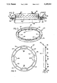
- FIG. 1 is an exploded perspective view of the component parts of an inflatable restraint system including a retainer ring, according to this invention
- FIG. 2 is an enlarged elevation of a mounting arrangement utilized in the restraint system of FIG. 1;
- FIG. 3 is a perspective view of the retainer ring
- FIG. 4 is a plan view of the retainer ring
- FIG. 5 is a side elevation of the retainer ring.
- FIG. 1 shows the component parts of an inflatable restraint system according to this invention.
- this type of restraint system is mounted in the hub of a steering wheel for deployment of the air bag upon detection of a threshold vehicle deceleration.
- the restraint system includes an inflatable air bag 10, having a circular central opening 12 in its inner end that is flanked by a first plurality of four mounting holes 14 and a second plurality of eight mounting holes 16 located in pairs between holes 14.
- a circular air bag retainer ring 20 includes a circular central opening 22 flanked by a plurality of four circumferentially-spaced mounting holes 24 and eight spring fingers or tabs 26 arranged in pairs between mounting holes 24. Mounting holes 24 correspond with air bag holes 14, while tabs 26 correspond to air bag holes 16.
- a base plate 30 has a circular opening 32 that is flanked by a first plurality of mounting holes 34 that correspond with air bag holes 14 and retainer holes 24.
- a second plurality of eight mounting holes 36 are interspersed in pairs between holes 34 and correspond to air bag holes 16 and retainer ring tabs 26.
- Eight mounting apertures 38 are spaced about the periphery of base plate 30.
- a pad retainer 40 includes a rectangular opening 42 having a circular central enlargement. Eight apertures 44, which mate with base plate apertures 38, are spaced around opening 42.
- An inflator 50 has a generally cylindrical casing including an upper portion 52 that includes a plurality of circumferentially-spaced radial pressure gas discharge ports 54. Upper portion 52 terminates in a central mounting flange 56 which incorporates four spaced mounting holes 58 that correspond to air bag mounting holes 14, retainer ring mounting holes 24 and base plate mounting holes 34.
- the usual rectangular container 62 and its decorative cover 64 are provided for covering the installed air bag.
- a plurality of fasteners such as bolts or rivets 66 are provided to mount container 62, as will be later described.
- retainer ring 20 is preferably made of steel and has a generally U-shaped cross-section formed of an upstanding outer peripheral wall 70 and a shorter inner wall 72 defining central opening 22. Walls 70 and 72 are interconnected by a circular floor 74 that includes mounting holes 24.
- the eight spring tabs 26 are lanced or stamped from inner wall 72 and floor 74 and each have a serpentine shape forming an outer engagement shoulder 76.
- the restraint system is assembled by inserting retainer ring 20 within air bag opening 12 and tabs 26 are projected through mounting holes 16. This action assembles bag 10 to ring 20 and aligns ring mounting holes 24 with air bag holes 14.
- tabs 26 are projected through base plate mounting holes 36 to assemble the air bag 10 to the base plate 30.
- Retainer ring 20 is formed so that all spring tabs 26 have their engagement shoulders 76 located radially slightly outwardly of the outer edges of mounting holes 36 in base plate 30. This enables tabs 26 to spring through holes 36 and tightly grip base plate 30 to clamp air bag 10 to the base plate 30, as shown in FIG. 2.
- this subassembly also facilitates further assembly of the inflatable restraint system. Further assembly of the system consists of mounting the inflator to the subassembly by aligning inflator mounting holes 58 with the aligned subassembly holes 14, 24, 34 and inserting rivets 80 which are upset to engage ring floor 74 and secure the inflator to the air bag and base plate.
- the restraint system assembly is completed by inserting fasteners 66 through pad retainer holes 44 and base plate holes 38 so that flanges of container 62 (not shown) and flanges (not shown) of decorative cover 64 are sandwiched between base plate 30 and pad retainer 40.
- the mating central circular openings 12, 22 and 32 all are sized to slidably receive inflator cylindrical portion 52, as shown in FIG. 2.
- the opening 42 of pad retainer 40 is large enough to clear inflator flange 56.
Abstract
Description
Claims (6)
Priority Applications (1)
Application Number | Priority Date | Filing Date | Title |
---|---|---|---|
US07/840,901 US5259641A (en) | 1992-02-25 | 1992-02-25 | Air bag attachment device |
Applications Claiming Priority (1)
Application Number | Priority Date | Filing Date | Title |
---|---|---|---|
US07/840,901 US5259641A (en) | 1992-02-25 | 1992-02-25 | Air bag attachment device |
Publications (1)
Publication Number | Publication Date |
---|---|
US5259641A true US5259641A (en) | 1993-11-09 |
Family
ID=25283519
Family Applications (1)
Application Number | Title | Priority Date | Filing Date |
---|---|---|---|
US07/840,901 Expired - Lifetime US5259641A (en) | 1992-02-25 | 1992-02-25 | Air bag attachment device |
Country Status (1)
Country | Link |
---|---|
US (1) | US5259641A (en) |
Cited By (22)
Publication number | Priority date | Publication date | Assignee | Title |
---|---|---|---|---|
US5320379A (en) * | 1993-05-05 | 1994-06-14 | Automotive Systems Laboratory, Inc. | Inflator mounting system |
US5443284A (en) * | 1991-10-17 | 1995-08-22 | Morton International, Inc. | Air bag cushion rivetless retainer ring, axial pin method |
US5470100A (en) * | 1994-08-25 | 1995-11-28 | General Motors Corporation | Air bag module inflator retainer |
US5501484A (en) * | 1995-03-20 | 1996-03-26 | Morton International, Inc. | Rivetless cushion retaining ring with tabs which lock the ring in place after rotation |
US5542692A (en) * | 1994-10-18 | 1996-08-06 | Morton International, Inc. | Inflatable cushion assembly and system |
US5577763A (en) * | 1995-03-29 | 1996-11-26 | Trw Inc. | Air bag mounting structure and method |
US5615907A (en) * | 1996-06-25 | 1997-04-01 | Morton International, Inc. | Airbag inflator retention tabs |
US5636858A (en) * | 1995-05-05 | 1997-06-10 | General Motors Corporation | Air bag module |
US5653006A (en) * | 1994-10-17 | 1997-08-05 | Morton International, Inc. | Passenger-side airbag module darted end caps and method of assembly |
US5678848A (en) * | 1996-01-17 | 1997-10-21 | Morton International, Inc. | Air bag module with combined assembly and mounting hardware |
US5683099A (en) * | 1995-03-28 | 1997-11-04 | Toyoda Gosei Co., Ltd. | Air bag device |
AU686971B1 (en) * | 1996-08-12 | 1998-02-12 | Autoliv Asp, Inc. | Integral steering wheel and airbag module |
WO1998012073A1 (en) * | 1996-09-19 | 1998-03-26 | Alliedsignal Deutschland Gmbh | Horn switch |
US5762359A (en) * | 1996-10-02 | 1998-06-09 | General Motors Corporation | Air bag module and steering wheel assembly |
WO1999020494A1 (en) * | 1997-10-21 | 1999-04-29 | Autoliv Development Ab | An air-bag arrangement |
US6161865A (en) * | 1999-05-28 | 2000-12-19 | Autoliv Asp, Inc. | Interlocking airbag attachment and module assembly |
US6206417B1 (en) | 1998-05-08 | 2001-03-27 | Autoliv Asp, Inc. | Air bag inflator exit gas dispersion features |
US20040041372A1 (en) * | 2002-08-27 | 2004-03-04 | Trw Automotive Safety Systems Gmbh | Gas bag module |
US20110169253A1 (en) * | 2010-01-08 | 2011-07-14 | Tk Holdings Inc. | Airbag module |
US20170355347A1 (en) * | 2015-01-08 | 2017-12-14 | Takata Corporation | Airbag device |
US20190143927A1 (en) * | 2016-04-26 | 2019-05-16 | Jacobo Casal Alonso | Gas bag unit and vehicle passenger safety system having such a gas bag unit, and manufactured method |
US10967712B2 (en) * | 2016-02-04 | 2021-04-06 | Kabushiki Kaisha Toyota Jidoshokki | Register panel mounting structure |
Citations (8)
Publication number | Priority date | Publication date | Assignee | Title |
---|---|---|---|---|
US3193613A (en) * | 1963-05-08 | 1965-07-06 | United Carr Inc | Combination conduit and wall connector device for the conduit |
US4063660A (en) * | 1977-04-06 | 1977-12-20 | Ware Fuse Corporation | Electrical outlet box |
US4934735A (en) * | 1988-12-12 | 1990-06-19 | General Motors Corporation | Switch assembly for modular occupant restraint system |
US4988119A (en) * | 1988-10-14 | 1991-01-29 | Irvin Automotive Products, Inc. | Vehicle occupant restraint system |
US5064218A (en) * | 1988-10-14 | 1991-11-12 | Takata, Inc. | Air cushion restraint device having reinforced inflation attachment |
JPH0455142A (en) * | 1990-06-21 | 1992-02-21 | Ikeda Bussan Co Ltd | Air bag device |
US5094477A (en) * | 1989-12-27 | 1992-03-10 | Ikeda Bussan Co., Ltd. | Airbag restraint system |
US5141247A (en) * | 1990-12-18 | 1992-08-25 | Trw Inc. | Air bag inflator assembly |
-
1992
- 1992-02-25 US US07/840,901 patent/US5259641A/en not_active Expired - Lifetime
Patent Citations (8)
Publication number | Priority date | Publication date | Assignee | Title |
---|---|---|---|---|
US3193613A (en) * | 1963-05-08 | 1965-07-06 | United Carr Inc | Combination conduit and wall connector device for the conduit |
US4063660A (en) * | 1977-04-06 | 1977-12-20 | Ware Fuse Corporation | Electrical outlet box |
US4988119A (en) * | 1988-10-14 | 1991-01-29 | Irvin Automotive Products, Inc. | Vehicle occupant restraint system |
US5064218A (en) * | 1988-10-14 | 1991-11-12 | Takata, Inc. | Air cushion restraint device having reinforced inflation attachment |
US4934735A (en) * | 1988-12-12 | 1990-06-19 | General Motors Corporation | Switch assembly for modular occupant restraint system |
US5094477A (en) * | 1989-12-27 | 1992-03-10 | Ikeda Bussan Co., Ltd. | Airbag restraint system |
JPH0455142A (en) * | 1990-06-21 | 1992-02-21 | Ikeda Bussan Co Ltd | Air bag device |
US5141247A (en) * | 1990-12-18 | 1992-08-25 | Trw Inc. | Air bag inflator assembly |
Cited By (29)
Publication number | Priority date | Publication date | Assignee | Title |
---|---|---|---|---|
US5443284A (en) * | 1991-10-17 | 1995-08-22 | Morton International, Inc. | Air bag cushion rivetless retainer ring, axial pin method |
WO1994025311A1 (en) * | 1993-05-05 | 1994-11-10 | Automotive Systems Laboratory, Inc. | Inflator mounting system |
US5320379A (en) * | 1993-05-05 | 1994-06-14 | Automotive Systems Laboratory, Inc. | Inflator mounting system |
US5470100A (en) * | 1994-08-25 | 1995-11-28 | General Motors Corporation | Air bag module inflator retainer |
US5653006A (en) * | 1994-10-17 | 1997-08-05 | Morton International, Inc. | Passenger-side airbag module darted end caps and method of assembly |
US5542692A (en) * | 1994-10-18 | 1996-08-06 | Morton International, Inc. | Inflatable cushion assembly and system |
EP0733516A1 (en) * | 1995-03-20 | 1996-09-25 | Morton International, Inc. | Rivetless cushion retaining ring with tabs which lock the ring in place after rotation |
US5501484A (en) * | 1995-03-20 | 1996-03-26 | Morton International, Inc. | Rivetless cushion retaining ring with tabs which lock the ring in place after rotation |
US5683099A (en) * | 1995-03-28 | 1997-11-04 | Toyoda Gosei Co., Ltd. | Air bag device |
US5577763A (en) * | 1995-03-29 | 1996-11-26 | Trw Inc. | Air bag mounting structure and method |
US5636858A (en) * | 1995-05-05 | 1997-06-10 | General Motors Corporation | Air bag module |
US5678848A (en) * | 1996-01-17 | 1997-10-21 | Morton International, Inc. | Air bag module with combined assembly and mounting hardware |
US5615907A (en) * | 1996-06-25 | 1997-04-01 | Morton International, Inc. | Airbag inflator retention tabs |
US5765861A (en) * | 1996-08-12 | 1998-06-16 | Morton International, Inc. | Integral steering wheel and airbag module |
AU686971B1 (en) * | 1996-08-12 | 1998-02-12 | Autoliv Asp, Inc. | Integral steering wheel and airbag module |
WO1998012073A1 (en) * | 1996-09-19 | 1998-03-26 | Alliedsignal Deutschland Gmbh | Horn switch |
US5762359A (en) * | 1996-10-02 | 1998-06-09 | General Motors Corporation | Air bag module and steering wheel assembly |
US6029992A (en) * | 1996-10-02 | 2000-02-29 | General Motors Corporation | Air bag module and steering wheel assembly |
WO1999020494A1 (en) * | 1997-10-21 | 1999-04-29 | Autoliv Development Ab | An air-bag arrangement |
US6206417B1 (en) | 1998-05-08 | 2001-03-27 | Autoliv Asp, Inc. | Air bag inflator exit gas dispersion features |
US6394491B2 (en) | 1998-05-08 | 2002-05-28 | Autoliv Asp, Inc. | Air bag inflation exit gas dispersion features |
US6161865A (en) * | 1999-05-28 | 2000-12-19 | Autoliv Asp, Inc. | Interlocking airbag attachment and module assembly |
US20040041372A1 (en) * | 2002-08-27 | 2004-03-04 | Trw Automotive Safety Systems Gmbh | Gas bag module |
US20110169253A1 (en) * | 2010-01-08 | 2011-07-14 | Tk Holdings Inc. | Airbag module |
US8622416B2 (en) * | 2010-01-08 | 2014-01-07 | Tk Holdings Inc. | Airbag module |
US20170355347A1 (en) * | 2015-01-08 | 2017-12-14 | Takata Corporation | Airbag device |
US10369955B2 (en) * | 2015-01-08 | 2019-08-06 | Joyson Safety Systems Japan K.K. | Airbag device |
US10967712B2 (en) * | 2016-02-04 | 2021-04-06 | Kabushiki Kaisha Toyota Jidoshokki | Register panel mounting structure |
US20190143927A1 (en) * | 2016-04-26 | 2019-05-16 | Jacobo Casal Alonso | Gas bag unit and vehicle passenger safety system having such a gas bag unit, and manufactured method |
Similar Documents
Publication | Publication Date | Title |
---|---|---|
US5259641A (en) | Air bag attachment device | |
US7255364B2 (en) | Driver air bag cover and attachment method | |
US5409256A (en) | Driver-side air bag module assembly | |
US5354093A (en) | Air bag module having integral cover attachment | |
US5762361A (en) | Airbag arrangement | |
US5284358A (en) | Air bag assembly | |
EP0733516A1 (en) | Rivetless cushion retaining ring with tabs which lock the ring in place after rotation | |
US6837513B2 (en) | Fixing method and structure of inflator, and airbag apparatus | |
US5518266A (en) | Vehicle safety apparatus including inflatable restraint | |
US5853228A (en) | Wheel cover retainer device | |
EP1283790B1 (en) | Airbag assembly | |
US5042881A (en) | Universal wheel liner | |
US6695343B1 (en) | Snap-in air bag module | |
JP2002524332A (en) | Snap-in airbag module | |
EP1403149B1 (en) | Snap together mounting of an air bag module and a vehicle steering wheel | |
US3512840A (en) | Wheel cover | |
US5560642A (en) | Driver air bag module assembly | |
US5340201A (en) | Snap-on dress wheel simulator | |
US6036222A (en) | Driver air bag module | |
US2576683A (en) | Hubcap | |
US20040231454A1 (en) | Pedal device | |
AU658540B2 (en) | Sliding cushion retainer with self-locking device | |
US6709004B1 (en) | Offset mounting system for assembling driver side airbag modules | |
US4657309A (en) | Wire wheel cover | |
US4229048A (en) | Wire wheel cover |
Legal Events
Date | Code | Title | Description |
---|---|---|---|
AS | Assignment |
Owner name: GENERAL MOTORS CORPORATION, MICHIGAN Free format text: ASSIGNMENT OF ASSIGNORS INTEREST.;ASSIGNORS:SCHENCK, DAVID P.;WEBBER, JAMES L.;REEL/FRAME:006057/0423 Effective date: 19920318 |
|
STCF | Information on status: patent grant |
Free format text: PATENTED CASE |
|
FPAY | Fee payment |
Year of fee payment: 4 |
|
FPAY | Fee payment |
Year of fee payment: 8 |
|
FPAY | Fee payment |
Year of fee payment: 12 |
|
AS | Assignment |
Owner name: DELPHI TECHNOLOGIES, INC., MICHIGAN Free format text: ASSIGNMENT OF ASSIGNORS INTEREST;ASSIGNOR:GENERAL MOTORS CORPORATION;REEL/FRAME:022399/0840 Effective date: 19990101 |