US5261101A - Method for calling and returning from subroutine that is invoked by either a near call or a far call - Google Patents
Method for calling and returning from subroutine that is invoked by either a near call or a far call Download PDFInfo
- Publication number
- US5261101A US5261101A US07/486,067 US48606790A US5261101A US 5261101 A US5261101 A US 5261101A US 48606790 A US48606790 A US 48606790A US 5261101 A US5261101 A US 5261101A
- Authority
- US
- United States
- Prior art keywords
- instruction
- subroutine
- far
- offset
- code segment
- Prior art date
- Legal status (The legal status is an assumption and is not a legal conclusion. Google has not performed a legal analysis and makes no representation as to the accuracy of the status listed.)
- Expired - Lifetime
Links
Images


Classifications
-
- G—PHYSICS
- G06—COMPUTING; CALCULATING OR COUNTING
- G06F—ELECTRIC DIGITAL DATA PROCESSING
- G06F9/00—Arrangements for program control, e.g. control units
- G06F9/06—Arrangements for program control, e.g. control units using stored programs, i.e. using an internal store of processing equipment to receive or retain programs
- G06F9/44—Arrangements for executing specific programs
- G06F9/448—Execution paradigms, e.g. implementations of programming paradigms
- G06F9/4482—Procedural
- G06F9/4484—Executing subprograms
- G06F9/4486—Formation of subprogram jump address
Definitions
- This invention relates to a method for calling and returning from a computer subroutine during execution of a computer program, and more specifically, a method for programming to handle both inter-segment and intra-segment subroutine linkage.
- a computer program is a collection of computer instructions ordered in a manner such that when the program is executed by the computer the computer will produce certain results.
- Computer programs can be very simple, containing only a few instructions. Conversely, computer programs can be very complex, containing millions of instructions. For example, a certain type of computer program called an operating system can be extremely complex and often contains over a million instructions.
- a subroutine is a set of instructions that is stored only once in a program, but can be “called” from several different places in a program.
- the computer starts executing the instructions in the subroutine.
- a "return” instruction in the subroutine is executed, the computer then "returns,” that is, resumes execution of the program at the instruction after the call.
- the set of instructions is as if it was inserted into the program at the call.
- Subroutines have several advantages over the duplicating of the set of instructions. Subroutines save space in the program, since the set of instructions is stored only once. Subroutines make it easier to organize complex programs. Subroutines make it easier to make changes to the set of instructions, since the changes need only be made once.
- the state-of-the-art computers such as those based on Intel 8086-family microprocessors, have special-purpose instructions to facilitate the calling of and returning from subroutines. Specifically, there are two instructions for calling and two instructions for returning.
- the Intel 8086-family of microprocessors uses a segmented addressing architecture.
- One such microprocessor is the Intel 80386, which is manufactured by the Intel Corporation of Santa Clara, Calif.
- the design and operation of the Intel 80386 is described in detail in a publication entitled "iAPX 386 Programmer's Reference Manual Including the iAPX 386 Numeric Supplement,” which is available from Intel Corporation and is hereby incorporated by reference.
- the Intel 80386 has one call instruction and one return instruction that are for invoking an intra-segment (a near) subroutine and another call instruction and return instruction that are for invoking an inter-segment (a far) subroutine.
- the addresses in the 8086-family comprise a segment and an offset. Each call and return must specify a segment and an offset. When a call or return is executed, the microprocessor combines the segment and the offset to form an address.
- the call instruction forms the address of the subroutine; the return instruction forms the address of the instruction to return to.
- the methods of calling and returning from subroutines is referred to as subroutine "linkage.”
- the near call and return are designed to be used when the call instruction and called subroutine are within the same segment when executed, that is, the current code segment.
- the code segment (CS) register contains information pointing to the current code segment.
- the processor pushes onto the stack the offset in the current segment of the instruction after the call instruction.
- the processor then jumps to the subroutine, which is located at a specified offset in the current code segment.
- the subroutine returns, it executes a near return instruction.
- the near return instruction When the near return instruction is executed, it pops the offset, which was pushed onto the stack by the near call instruction, from the stack.
- the processor then forms an address based on current code segment and the offset. This address is the address of the instruction after the near call instruction.
- the processor then proceeds to execute the instruction at that address.
- the limitation of the near call and return instructions is that only subroutines within the same segment can be called.
- the far call and return instructions have no such limitation.
- the far call and return instructions work similarly to their near counterparts, except that these instructions push and pop both a segment and offset component.
- the far call specifies both a segment and an offset for the subroutine. Consequently, the current setting of the CS register is saved on the stack in addition to the offset of the instruction after the call.
- the processor pops the segment and offset values pushed by the corresponding call instruction, forms an address, and returns to that address.
- the far call can specify any address and, unlike the near call, is not limited to those addresses within the current code segment.
- a typical subroutine is designed to be called either by a near call instruction or a far call instruction. If designed to be called by a near call instruction, then the subroutine executes a near return instruction, which pops only the offset, to return. If designed to be called by a far call instruction, then the subroutine executes a far return instruction, which pops both the segment and offset, to return. If a subroutine that is designed to be called by a far call is invoked by a near call, then the subroutine will not return to the instruction after the far call. This mixing of near call with far return or mixing of a far call with a near return will result in a program error.
- a subroutine is designed to be invoked by both a near call and a far call.
- the subroutine has a near entry point and a far entry point.
- the near return instruction is executed, it pops the offset pushed by the instruction executed at the far entry point.
- the processor then continues execution at the far return instruction, which the offset points to, to effect a return to the instruction after the far call.
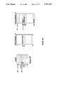
- FIGS. 1A through 1D trace the execution of a near call and a near return of prior systems.
- FIGS. 2A through 2D trace the execution of a far call and far return of prior systems.
- FIGS. 3A through 3D trace the execution of a near call and near return.
- FIGS. 4A through 4F trace the execution of a far call and far return.
- FIGS. 5A through 5D trace the execution of a near call and near return of a preferred embodiment of the present invention.
- FIGS. 6A through 6F trace the execution of a far call and far return of a preferred embodiment of the present invention.
- a preferred embodiment of the present invention provides a method for linking subroutines in a way that the subroutine may be invoked using both a far call and a near call.
- the description of the invention that follows uses the term "address" symbolically.
- the instructions referred to may be multi-byte instructions.
- the addresses used refer to the logical addresses of the instructions.
- the "CALLN 500" stored at logical address 150 is a multi-byte instruction.
- the next instruction is shown at address 151, instead of address 150 plus the number of bytes in the "CALLN 500" instruction.
- FIGS. 1A through 1D show the linking method for calling a near subroutine.
- the stack shows the state of the stack at various times during calling and returning from the subroutine.
- the Stack Segment (SS) register points to the segment that contains the stack, and the Stack Pointer (SP) register contains the offset in SS of the top of the stack.
- the code segment contains the program that calls the subroutine and the subroutine.
- the Code Segment (CS) register points to the segment that contains the code
- the Instruction Pointer (IP) register contains an offset into the code segment of the instruction currently being executed.
- a segment register points either directly or indirectly to a segment.
- the subroutine is stored at offset 500 through 512 in the code segment.
- the entry point of the subroutine being at offset 500.
- the near return (RETN) for the subroutine is stored at offset 512.
- the near call which invokes the subroutine is stored at offset 150 in the code segment.
- the call instruction is "CALLN 500.”
- the "CALLN” represents the operation code for the near call, and the "500” represents the entry point of the subroutine to be invoked.
- FIG. 1A shows the state of stack, code segment, and associated registers (referred to as state of the processor in the following) just before the execution of the CALLN instruction at offset 150 in the code segment.
- FIG. 1B shows the state of the processor after execution of the CALLN instruction.
- the CALLN was executed, the next address after the CALLN instruction, that is, offset 151 in the code segment, was pushed onto the stack.
- the IP register was set to 500, which is the entry point of the subroutine.
- FIG. 1C shows the state of the processor just before the subroutine executes the near return (RETN) instruction.
- the IP register points to the RETN instruction.
- the subroutine may have pushed data on and popped data off the stack, the SP register points to the return offset in the code segment.
- the RETN instruction causes the stack to be popped and the IP register to be set to the popped value, offset 151 in this example.
- FIG. 1D shows the state of the processor after the RETN instruction is executed.
- the stack no longer contains the offset and the IP register points to the instruction immediately following the CALLN instruction.
- FIGS. 2A through 2D show an example of the linking method of prior systems for calling a far subroutine.
- the stack shows the state of the stack before the far call (CALLF) instruction is executed.
- the SS register points to the segment that contains the stack, and the SP register contains the offset in SS of the top of the stack.
- the code segment number 10 contains the program that calls the subroutine
- the code segment number 27 contains the subroutine.
- the CS register points to the code segment currently being executed.
- the IP register contains an offset into the current code segment of the instruction to be executed next.
- the subroutine is stored at offset 500 through 512 in the code segment number 27.
- the entry point of the subroutine is at offset 500 in code segment number 27.
- the far return (RETF) from the subroutine is stored at offset 512 in code segment number 27.
- the far call which invokes the subroutine is stored at offset 150 in code segment number 10.
- the call instruction is "CALLF 27:500.”
- the "CALLF” represents the operation code for the far call and the "27:500” represents the entry point of the subroutine to be invoked.
- the "27” is the code segment number of the segment where the subroutine is located.
- the "500” contains the offset in code segment number 27 of the entry point to the subroutine.
- FIG. 2A shows the state of the processor before the CALLF instruction is executed.
- the CALLF instruction causes the current code segment number 10 to be pushed onto the stack.
- the offset of the instruction after the CALLF that is, offset 151 is also pushed onto the stack.
- the CALLF instruction causes the CS register to be set to 27, which is the segment number where the subroutine is located.
- the CALLF instruction also causes the IP register to be set to 500, which is the offset into code segment number 27 of the entry point of the subroutine.
- FIG. 2C shows the state of the processor before the RETF instruction of the subroutine is executed.
- the RETF instruction causes the stack to be popped twice.
- the IP register is set to first popped value which is the offset in code segment number 10 at which the subroutine is to return to.
- the CS register is set to point to code segment number 10. This effects the return from the subroutine.
- FIG. 2D shows the state of the processor after the return from the subroutine.
- FIGS. 3A through 3D show a method of near subroutine linkage.
- FIG. 3A shows a code segment which contains a subroutine.
- the subroutine has two instructions added to support subroutine linkage.
- One instruction is a RETF instruction and the other instruction is a PUSH instruction.
- the PUSH instruction pushes the offset of the RETF instruction onto the stack.
- the RETF instruction is stored two instructions before the entry point of the subroutine at offset 498
- the PUSH instruction is stored one instruction before the entry point at offset 499.
- FIGS. 3A through 3D The instruction sequence shown in FIGS. 3A through 3D is identical to the sequence shown in FIGS. 1A through 1D.
- the advantages of including the RETF and the PUSH instructions before a subroutine can be illustrated by a far call invoking the subroutine.
- FIGS. 4A through 4F trace the execution of a far call to the subroutine.
- the subroutine is stored in a different code segment than the location of the far call.
- the subroutine is the same as that shown in FIG. 3A, except that it is stored in a different code segment.
- the same two instructions, RETF and PUSH, are placed before the entry point at offset 500.
- the subroutine also has a RETN instruction at offset 512.
- the call instruction in code segment 10 is a far call that specifies an entry point of offset 499, rather than 500.
- the entry point at offset 499 is referred to as the far entry point.
- the entry point at offset 500 is referred to as the near entry point.
- FIG. 4A shows the state of the processor before the "CALLF 27:499" instruction is executed.
- the execution of the far call causes the return address, that is, the code segment number 10 and the offset 151, to be pushed onto the stack.
- the execution also causes the CS register to be set to 27 and the IP register to be set to 499.
- the offset 499 can be considered a secondary entry point into the subroutine.
- the 499 entry point is used by far calls.
- FIG. 4B shows the state of the processor after the CALLF instruction is executed.
- FIG. 4C shows the state of the processor after the "PUSH 498" instruction is executed.
- the PUSH instruction pushes the offset 498 of the RETF instruction onto the stack and the IP register is set to point to the next instruction, which is at offset 500.
- FIG. 4D shows the state of the processor before the RETN instruction is executed.
- the top of the stack contains the offset 498 of the RETF instruction.
- the offset 498 is popped from the stack and the IP register is set to that value.
- FIG. 4E shows the state of the processor after the RETN is executed.
- the IP register points to the RETF instruction.
- offset 151 and code segment number 10 are popped from the stack.
- the CS register is set to point to code segment number 10 and the IP register is set to point to the offset 151.
- FIG. 4F shows the state of the processor after the RETF is executed.
- the CS register points to code segment number 10, and the IP register points to the instruction after the CALLF instruction to complete the return from the subroutine.
- a far call instruction of the alternate entry point at offset 499 allows the offset of the RETF instruction to be pushed onto the stack.
- the offset of the RETF instruction is popped from the stack and execution continues at the RETF instruction.
- the RETF instruction then causes the code segment number and offset of the return address to be popped from the stack to effect the far return.
- FIGS. 5A through 5D and 6A through 6F show a preferred embodiment of the present invention.
- FIGS. 5A through 5D trace the execution of the near call and near return. Again, the execution is the same as shown in FIGS. 1A through 1D and 3A through 3D.
- the subroutine stored at offset 500 through 512 is the same.
- a RETF instruction and a "PUSH 0" instruction are included in the code segment.
- the RETF instruction is stored at offset 0 in the code segment and the "PUSH 0" instruction is stored at offset 499.
- the execution of the call and return functions is similar to the embodiment shown in FIGS. 3A through 3D and 4A through 4F.
- An advantage of the preferred embodiment is that for certain computers, such as those based on the 8086-family, the "PUSH 0" instruction can be stored as a 2-byte instruction: 1-byte operation code and 1 byte of immediate data, the 0. Whereas PUSH instructions typically are a 6-byte instruction.
- the RETF instruction needs to be stored once for each code segment, rather than once for each subroutine. In other words, all the subroutines in a given code segment can share the same RETF instruction.
- one byte of immediate data can refer to offsets less than 128 or greater than 65,407.
- FIGS. 6A through 6F trace the execution of a far call and far return in the preferred embodiment. Tracing the execution of the far call and far return will show how the same subroutine can be invoked either by a far call or a near call and return to the proper address.
- FIG. 6A shows the state of the processor before the "CALLF 27:499" instruction is executed. The execution of the far call causes the return address, that is, the code segment number 10 and the offset 151, to be pushed onto the stack. The execution also causes the CS register to be set to 27 and the IP register to be set to 499. The offset 499 can be considered a secondary entry point into the subroutine. The 499 entry point is used by far calls.
- FIG. 6B shows the state of the processor after the CALLF instruction is executed.
- FIG. 6C shows the state of the processor after the "PUSH 0" instruction is executed.
- the PUSH instruction pushes the offset 0, which is the offset of the RETF instruction, onto the stack and the IP register is set to point to the next instruction offset 500.
- FIG. 6D shows the state of the processor before the RETN instruction is executed.
- the top of the stack contains offset 0, which is the offset of the RETF instruction.
- the offset 0 is popped from the stack and the IP register is set to that value.
- FIG. 6E shows the state of the processor after the RETN instruction is executed.
- the IP register points to the RETF instruction.
- offset 151 and code segment number 10 are popped from the stack.
- the CS register is set to point to code segment number 10 and the IP register is set to point to the offset 151.
- FIG. 6F shows the state of the processor after the RETF instruction is executed.
- the IP register points to the instruction after the CALLF instruction to complete the return from the subroutine.
Abstract
Description
Claims (17)
Priority Applications (1)
| Application Number | Priority Date | Filing Date | Title |
|---|---|---|---|
| US07/486,067 US5261101A (en) | 1990-02-28 | 1990-02-28 | Method for calling and returning from subroutine that is invoked by either a near call or a far call |
Applications Claiming Priority (1)
| Application Number | Priority Date | Filing Date | Title |
|---|---|---|---|
| US07/486,067 US5261101A (en) | 1990-02-28 | 1990-02-28 | Method for calling and returning from subroutine that is invoked by either a near call or a far call |
Publications (1)
| Publication Number | Publication Date |
|---|---|
| US5261101A true US5261101A (en) | 1993-11-09 |
Family
ID=23930470
Family Applications (1)
| Application Number | Title | Priority Date | Filing Date |
|---|---|---|---|
| US07/486,067 Expired - Lifetime US5261101A (en) | 1990-02-28 | 1990-02-28 | Method for calling and returning from subroutine that is invoked by either a near call or a far call |
Country Status (1)
| Country | Link |
|---|---|
| US (1) | US5261101A (en) |
Cited By (17)
| Publication number | Priority date | Publication date | Assignee | Title |
|---|---|---|---|---|
| EP0603632A2 (en) * | 1992-12-23 | 1994-06-29 | Siemens Aktiengesellschaft | Method for controlling a processor device |
| US5655154A (en) * | 1993-07-06 | 1997-08-05 | Microsoft Corporation | Method and system for sharing utilities between operating systems |
| US5848246A (en) * | 1996-07-01 | 1998-12-08 | Sun Microsystems, Inc. | Object-oriented system, method and article of manufacture for a client-server session manager in an interprise computing framework system |
| US5987245A (en) * | 1996-07-01 | 1999-11-16 | Sun Microsystems, Inc. | Object-oriented system, method and article of manufacture (#12) for a client-server state machine framework |
| US5999972A (en) * | 1996-07-01 | 1999-12-07 | Sun Microsystems, Inc. | System, method and article of manufacture for a distributed computer system framework |
| US6038590A (en) * | 1996-07-01 | 2000-03-14 | Sun Microsystems, Inc. | Object-oriented system, method and article of manufacture for a client-server state machine in an interprise computing framework system |
| US6266709B1 (en) | 1996-07-01 | 2001-07-24 | Sun Microsystems, Inc. | Object-oriented system, method and article of manufacture for a client-server failure reporting process |
| US6272555B1 (en) | 1996-07-01 | 2001-08-07 | Sun Microsystems, Inc. | Object-oriented system, method and article of manufacture for a client-server-centric interprise computing framework system |
| US6304893B1 (en) | 1996-07-01 | 2001-10-16 | Sun Microsystems, Inc. | Object-oriented system, method and article of manufacture for a client-server event driven message framework in an interprise computing framework system |
| US6363473B1 (en) * | 1999-04-01 | 2002-03-26 | Compaq Information Technologies Group, L.P. | Simulated memory stack in a stackless environment |
| US6424991B1 (en) | 1996-07-01 | 2002-07-23 | Sun Microsystems, Inc. | Object-oriented system, method and article of manufacture for a client-server communication framework |
| US6434598B1 (en) | 1996-07-01 | 2002-08-13 | Sun Microsystems, Inc. | Object-oriented system, method and article of manufacture for a client-server graphical user interface (#9) framework in an interprise computing framework system |
| US6658602B1 (en) | 1999-05-27 | 2003-12-02 | Autonetworks Technologies, Ltd. | Apparatus for detecting abnormal execution of program |
| WO2004001586A1 (en) * | 2002-06-24 | 2003-12-31 | Infineon Technologies Ag | Device and method for processing a sequence of jump instructions |
| US20050138263A1 (en) * | 2003-12-23 | 2005-06-23 | Mckeen Francis X. | Method and apparatus to retain system control when a buffer overflow attack occurs |
| US20050154868A1 (en) * | 2002-06-24 | 2005-07-14 | Dirk Rabe | Apparatus and method for processing a sequence of jump instructions |
| US20060224866A1 (en) * | 2005-03-30 | 2006-10-05 | Arm Limited | Selecting subroutine return mechanisms |
Citations (1)
| Publication number | Priority date | Publication date | Assignee | Title |
|---|---|---|---|---|
| US4944578A (en) * | 1988-07-21 | 1990-07-31 | Telex Communications | Color graphic imager utilizing a liquid crystal display |
-
1990
- 1990-02-28 US US07/486,067 patent/US5261101A/en not_active Expired - Lifetime
Patent Citations (1)
| Publication number | Priority date | Publication date | Assignee | Title |
|---|---|---|---|---|
| US4944578A (en) * | 1988-07-21 | 1990-07-31 | Telex Communications | Color graphic imager utilizing a liquid crystal display |
Cited By (21)
| Publication number | Priority date | Publication date | Assignee | Title |
|---|---|---|---|---|
| EP0603632A3 (en) * | 1992-12-23 | 1995-01-04 | Siemens Ag | Method for controlling a processor device. |
| EP0603632A2 (en) * | 1992-12-23 | 1994-06-29 | Siemens Aktiengesellschaft | Method for controlling a processor device |
| US5655154A (en) * | 1993-07-06 | 1997-08-05 | Microsoft Corporation | Method and system for sharing utilities between operating systems |
| US6434598B1 (en) | 1996-07-01 | 2002-08-13 | Sun Microsystems, Inc. | Object-oriented system, method and article of manufacture for a client-server graphical user interface (#9) framework in an interprise computing framework system |
| US5848246A (en) * | 1996-07-01 | 1998-12-08 | Sun Microsystems, Inc. | Object-oriented system, method and article of manufacture for a client-server session manager in an interprise computing framework system |
| US5987245A (en) * | 1996-07-01 | 1999-11-16 | Sun Microsystems, Inc. | Object-oriented system, method and article of manufacture (#12) for a client-server state machine framework |
| US5999972A (en) * | 1996-07-01 | 1999-12-07 | Sun Microsystems, Inc. | System, method and article of manufacture for a distributed computer system framework |
| US6038590A (en) * | 1996-07-01 | 2000-03-14 | Sun Microsystems, Inc. | Object-oriented system, method and article of manufacture for a client-server state machine in an interprise computing framework system |
| US6266709B1 (en) | 1996-07-01 | 2001-07-24 | Sun Microsystems, Inc. | Object-oriented system, method and article of manufacture for a client-server failure reporting process |
| US6272555B1 (en) | 1996-07-01 | 2001-08-07 | Sun Microsystems, Inc. | Object-oriented system, method and article of manufacture for a client-server-centric interprise computing framework system |
| US6304893B1 (en) | 1996-07-01 | 2001-10-16 | Sun Microsystems, Inc. | Object-oriented system, method and article of manufacture for a client-server event driven message framework in an interprise computing framework system |
| US6424991B1 (en) | 1996-07-01 | 2002-07-23 | Sun Microsystems, Inc. | Object-oriented system, method and article of manufacture for a client-server communication framework |
| US6363473B1 (en) * | 1999-04-01 | 2002-03-26 | Compaq Information Technologies Group, L.P. | Simulated memory stack in a stackless environment |
| US6658602B1 (en) | 1999-05-27 | 2003-12-02 | Autonetworks Technologies, Ltd. | Apparatus for detecting abnormal execution of program |
| WO2004001586A1 (en) * | 2002-06-24 | 2003-12-31 | Infineon Technologies Ag | Device and method for processing a sequence of jump instructions |
| DE10228151A1 (en) * | 2002-06-24 | 2004-02-05 | Infineon Technologies Ag | Device and method for processing a sequence of jump instructions |
| US20050154868A1 (en) * | 2002-06-24 | 2005-07-14 | Dirk Rabe | Apparatus and method for processing a sequence of jump instructions |
| US7415602B2 (en) | 2002-06-24 | 2008-08-19 | Infineon Technologies Ag | Apparatus and method for processing a sequence of jump instructions |
| US20050138263A1 (en) * | 2003-12-23 | 2005-06-23 | Mckeen Francis X. | Method and apparatus to retain system control when a buffer overflow attack occurs |
| US20060224866A1 (en) * | 2005-03-30 | 2006-10-05 | Arm Limited | Selecting subroutine return mechanisms |
| US7401210B2 (en) * | 2005-03-30 | 2008-07-15 | Arm Limited | Selecting subroutine return mechanisms |
Similar Documents
| Publication | Publication Date | Title |
|---|---|---|
| US5261101A (en) | Method for calling and returning from subroutine that is invoked by either a near call or a far call | |
| US5490256A (en) | Method and mechanism for calling 32-bit functions from 16-bit functions | |
| Hauck et al. | Burroughs' B6500/B7500 stack mechanism | |
| US5734904A (en) | Method and system for calling one of a set of routines designed for direct invocation by programs of a second type when invoked by a program of the first type | |
| US4468736A (en) | Mechanism for creating dependency free code for multiple processing elements | |
| CA1214566A (en) | Method of synchronizing the sequence by which a variety of randomly called unrelated activities are executed in a digital processor | |
| JPH02272627A (en) | Digital computer system and method of invocation of procedure of the same | |
| KR20010006995A (en) | Application management | |
| US4454580A (en) | Program call method and call instruction execution apparatus | |
| US6256783B1 (en) | Object conversion apparatus, object conversion method and program storing medium | |
| EP0237637B1 (en) | A method for the relocation of linked control blocks | |
| US4388682A (en) | Microprogrammable instruction translator | |
| EP0144779B1 (en) | Parallel processing computer | |
| US6438621B1 (en) | In-memory modification of computer programs | |
| US4787034A (en) | Program access system | |
| EP0240108A2 (en) | A data processing system | |
| US4499535A (en) | Digital computer system having descriptors for variable length addressing for a plurality of instruction dialects | |
| EP0417916B1 (en) | Procedure state descriptor system for digital data processors | |
| EP0363174A3 (en) | Branch on bit processing | |
| JP2620545B2 (en) | Editing device driven by table | |
| US7356809B1 (en) | Programmable interpretive virtual machine | |
| US6321319B2 (en) | Computer system for allowing a two word jump instruction to be executed in the same number of cycles as a single word jump instruction | |
| US5093784A (en) | Data processor with efficient transfer between subroutines and main program | |
| Corsini et al. | The implementation of abstract objects in a capability based addressing architecture | |
| KR0160681B1 (en) | Robot control method |
Legal Events
| Date | Code | Title | Description |
|---|---|---|---|
| AS | Assignment |
Owner name: MICROSOFT CORPORATION, A CORP. OF DE, WASHINGTON Free format text: ASSIGNMENT OF ASSIGNORS INTEREST.;ASSIGNOR:FENWICK, THOMAS;REEL/FRAME:005245/0913 Effective date: 19900223 |
|
| STCF | Information on status: patent grant |
Free format text: PATENTED CASE |
|
| FEPP | Fee payment procedure |
Free format text: PAYOR NUMBER ASSIGNED (ORIGINAL EVENT CODE: ASPN); ENTITY STATUS OF PATENT OWNER: LARGE ENTITY |
|
| FPAY | Fee payment |
Year of fee payment: 4 |
|
| FEPP | Fee payment procedure |
Free format text: PAYER NUMBER DE-ASSIGNED (ORIGINAL EVENT CODE: RMPN); ENTITY STATUS OF PATENT OWNER: LARGE ENTITY Free format text: PAYOR NUMBER ASSIGNED (ORIGINAL EVENT CODE: ASPN); ENTITY STATUS OF PATENT OWNER: LARGE ENTITY |
|
| FPAY | Fee payment |
Year of fee payment: 8 |
|
| FPAY | Fee payment |
Year of fee payment: 12 |
|
| AS | Assignment |
Owner name: MICROSOFT TECHNOLOGY LICENSING, LLC, WASHINGTON Free format text: ASSIGNMENT OF ASSIGNORS INTEREST;ASSIGNOR:MICROSOFT CORPORATION;REEL/FRAME:034766/0001 Effective date: 20141014 |