US5262220A - High strength structure assembly and method of making the same - Google Patents
High strength structure assembly and method of making the same Download PDFInfo
- Publication number
- US5262220A US5262220A US07/716,957 US71695791A US5262220A US 5262220 A US5262220 A US 5262220A US 71695791 A US71695791 A US 71695791A US 5262220 A US5262220 A US 5262220A
- Authority
- US
- United States
- Prior art keywords
- recited
- ribs
- bonding
- panel
- sheet
- Prior art date
- Legal status (The legal status is an assumption and is not a legal conclusion. Google has not performed a legal analysis and makes no representation as to the accuracy of the status listed.)
- Expired - Fee Related
Links
- 238000004519 manufacturing process Methods 0.000 title description 6
- 230000007935 neutral effect Effects 0.000 claims abstract description 9
- 230000006835 compression Effects 0.000 claims description 7
- 238000007906 compression Methods 0.000 claims description 7
- 230000013011 mating Effects 0.000 claims description 5
- 230000008901 benefit Effects 0.000 description 6
- 238000005452 bending Methods 0.000 description 5
- 238000000034 method Methods 0.000 description 5
- PXHVJJICTQNCMI-UHFFFAOYSA-N Nickel Chemical compound [Ni] PXHVJJICTQNCMI-UHFFFAOYSA-N 0.000 description 4
- 239000000463 material Substances 0.000 description 4
- 239000000956 alloy Substances 0.000 description 3
- 229910045601 alloy Inorganic materials 0.000 description 3
- 238000003801 milling Methods 0.000 description 3
- XKRFYHLGVUSROY-UHFFFAOYSA-N Argon Chemical compound [Ar] XKRFYHLGVUSROY-UHFFFAOYSA-N 0.000 description 2
- RTAQQCXQSZGOHL-UHFFFAOYSA-N Titanium Chemical compound [Ti] RTAQQCXQSZGOHL-UHFFFAOYSA-N 0.000 description 2
- 229910052782 aluminium Inorganic materials 0.000 description 2
- XAGFODPZIPBFFR-UHFFFAOYSA-N aluminium Chemical compound [Al] XAGFODPZIPBFFR-UHFFFAOYSA-N 0.000 description 2
- 230000000694 effects Effects 0.000 description 2
- 239000011229 interlayer Substances 0.000 description 2
- 229910052751 metal Inorganic materials 0.000 description 2
- 239000002184 metal Substances 0.000 description 2
- 229910052759 nickel Inorganic materials 0.000 description 2
- 230000002093 peripheral effect Effects 0.000 description 2
- 239000010936 titanium Substances 0.000 description 2
- 229910052719 titanium Inorganic materials 0.000 description 2
- 229910052786 argon Inorganic materials 0.000 description 1
- 238000005520 cutting process Methods 0.000 description 1
- 238000013461 design Methods 0.000 description 1
- 238000009792 diffusion process Methods 0.000 description 1
- 230000003467 diminishing effect Effects 0.000 description 1
- 239000011888 foil Substances 0.000 description 1
- 238000000227 grinding Methods 0.000 description 1
- 238000010348 incorporation Methods 0.000 description 1
- 239000011261 inert gas Substances 0.000 description 1
- 238000005304 joining Methods 0.000 description 1
- 238000003754 machining Methods 0.000 description 1
- 230000007246 mechanism Effects 0.000 description 1
- 150000002739 metals Chemical class 0.000 description 1
- 238000012986 modification Methods 0.000 description 1
- 230000004048 modification Effects 0.000 description 1
- 230000008569 process Effects 0.000 description 1
- 239000002994 raw material Substances 0.000 description 1
- 230000003014 reinforcing effect Effects 0.000 description 1
- 230000008439 repair process Effects 0.000 description 1
- 238000012552 review Methods 0.000 description 1
- 239000007787 solid Substances 0.000 description 1
- 230000003068 static effect Effects 0.000 description 1
- 239000000126 substance Substances 0.000 description 1
- 230000007704 transition Effects 0.000 description 1
Images


Classifications
-
- B—PERFORMING OPERATIONS; TRANSPORTING
- B32—LAYERED PRODUCTS
- B32B—LAYERED PRODUCTS, i.e. PRODUCTS BUILT-UP OF STRATA OF FLAT OR NON-FLAT, e.g. CELLULAR OR HONEYCOMB, FORM
- B32B15/00—Layered products comprising a layer of metal
- B32B15/04—Layered products comprising a layer of metal comprising metal as the main or only constituent of a layer, which is next to another layer of the same or of a different material
- B32B15/043—Layered products comprising a layer of metal comprising metal as the main or only constituent of a layer, which is next to another layer of the same or of a different material of metal
-
- B—PERFORMING OPERATIONS; TRANSPORTING
- B32—LAYERED PRODUCTS
- B32B—LAYERED PRODUCTS, i.e. PRODUCTS BUILT-UP OF STRATA OF FLAT OR NON-FLAT, e.g. CELLULAR OR HONEYCOMB, FORM
- B32B15/00—Layered products comprising a layer of metal
- B32B15/20—Layered products comprising a layer of metal comprising aluminium or copper
-
- B—PERFORMING OPERATIONS; TRANSPORTING
- B32—LAYERED PRODUCTS
- B32B—LAYERED PRODUCTS, i.e. PRODUCTS BUILT-UP OF STRATA OF FLAT OR NON-FLAT, e.g. CELLULAR OR HONEYCOMB, FORM
- B32B3/00—Layered products comprising a layer with external or internal discontinuities or unevennesses, or a layer of non-planar form; Layered products having particular features of form
- B32B3/26—Layered products comprising a layer with external or internal discontinuities or unevennesses, or a layer of non-planar form; Layered products having particular features of form characterised by a particular shape of the outline of the cross-section of a continuous layer; characterised by a layer with cavities or internal voids ; characterised by an apertured layer
- B32B3/30—Layered products comprising a layer with external or internal discontinuities or unevennesses, or a layer of non-planar form; Layered products having particular features of form characterised by a particular shape of the outline of the cross-section of a continuous layer; characterised by a layer with cavities or internal voids ; characterised by an apertured layer characterised by a layer formed with recesses or projections, e.g. hollows, grooves, protuberances, ribs
-
- B—PERFORMING OPERATIONS; TRANSPORTING
- B64—AIRCRAFT; AVIATION; COSMONAUTICS
- B64C—AEROPLANES; HELICOPTERS
- B64C1/00—Fuselages; Constructional features common to fuselages, wings, stabilising surfaces or the like
- B64C1/06—Frames; Stringers; Longerons ; Fuselage sections
- B64C1/068—Fuselage sections
-
- E—FIXED CONSTRUCTIONS
- E04—BUILDING
- E04C—STRUCTURAL ELEMENTS; BUILDING MATERIALS
- E04C2/00—Building elements of relatively thin form for the construction of parts of buildings, e.g. sheet materials, slabs, or panels
- E04C2/30—Building elements of relatively thin form for the construction of parts of buildings, e.g. sheet materials, slabs, or panels characterised by the shape or structure
- E04C2/34—Building elements of relatively thin form for the construction of parts of buildings, e.g. sheet materials, slabs, or panels characterised by the shape or structure composed of two or more spaced sheet-like parts
-
- B—PERFORMING OPERATIONS; TRANSPORTING
- B32—LAYERED PRODUCTS
- B32B—LAYERED PRODUCTS, i.e. PRODUCTS BUILT-UP OF STRATA OF FLAT OR NON-FLAT, e.g. CELLULAR OR HONEYCOMB, FORM
- B32B2311/00—Metals, their alloys or their compounds
- B32B2311/18—Titanium
-
- B—PERFORMING OPERATIONS; TRANSPORTING
- B32—LAYERED PRODUCTS
- B32B—LAYERED PRODUCTS, i.e. PRODUCTS BUILT-UP OF STRATA OF FLAT OR NON-FLAT, e.g. CELLULAR OR HONEYCOMB, FORM
- B32B2311/00—Metals, their alloys or their compounds
- B32B2311/22—Nickel or cobalt
-
- B—PERFORMING OPERATIONS; TRANSPORTING
- B32—LAYERED PRODUCTS
- B32B—LAYERED PRODUCTS, i.e. PRODUCTS BUILT-UP OF STRATA OF FLAT OR NON-FLAT, e.g. CELLULAR OR HONEYCOMB, FORM
- B32B2311/00—Metals, their alloys or their compounds
- B32B2311/24—Aluminium
-
- B—PERFORMING OPERATIONS; TRANSPORTING
- B32—LAYERED PRODUCTS
- B32B—LAYERED PRODUCTS, i.e. PRODUCTS BUILT-UP OF STRATA OF FLAT OR NON-FLAT, e.g. CELLULAR OR HONEYCOMB, FORM
- B32B2605/00—Vehicles
- B32B2605/18—Aircraft
-
- Y—GENERAL TAGGING OF NEW TECHNOLOGICAL DEVELOPMENTS; GENERAL TAGGING OF CROSS-SECTIONAL TECHNOLOGIES SPANNING OVER SEVERAL SECTIONS OF THE IPC; TECHNICAL SUBJECTS COVERED BY FORMER USPC CROSS-REFERENCE ART COLLECTIONS [XRACs] AND DIGESTS
- Y10—TECHNICAL SUBJECTS COVERED BY FORMER USPC
- Y10T—TECHNICAL SUBJECTS COVERED BY FORMER US CLASSIFICATION
- Y10T428/00—Stock material or miscellaneous articles
- Y10T428/12—All metal or with adjacent metals
- Y10T428/1234—Honeycomb, or with grain orientation or elongated elements in defined angular relationship in respective components [e.g., parallel, inter- secting, etc.]
-
- Y—GENERAL TAGGING OF NEW TECHNOLOGICAL DEVELOPMENTS; GENERAL TAGGING OF CROSS-SECTIONAL TECHNOLOGIES SPANNING OVER SEVERAL SECTIONS OF THE IPC; TECHNICAL SUBJECTS COVERED BY FORMER USPC CROSS-REFERENCE ART COLLECTIONS [XRACs] AND DIGESTS
- Y10—TECHNICAL SUBJECTS COVERED BY FORMER USPC
- Y10T—TECHNICAL SUBJECTS COVERED BY FORMER US CLASSIFICATION
- Y10T428/00—Stock material or miscellaneous articles
- Y10T428/12—All metal or with adjacent metals
- Y10T428/12347—Plural layers discontinuously bonded [e.g., spot-weld, mechanical fastener, etc.]
-
- Y—GENERAL TAGGING OF NEW TECHNOLOGICAL DEVELOPMENTS; GENERAL TAGGING OF CROSS-SECTIONAL TECHNOLOGIES SPANNING OVER SEVERAL SECTIONS OF THE IPC; TECHNICAL SUBJECTS COVERED BY FORMER USPC CROSS-REFERENCE ART COLLECTIONS [XRACs] AND DIGESTS
- Y10—TECHNICAL SUBJECTS COVERED BY FORMER USPC
- Y10T—TECHNICAL SUBJECTS COVERED BY FORMER US CLASSIFICATION
- Y10T428/00—Stock material or miscellaneous articles
- Y10T428/24—Structurally defined web or sheet [e.g., overall dimension, etc.]
- Y10T428/24174—Structurally defined web or sheet [e.g., overall dimension, etc.] including sheet or component perpendicular to plane of web or sheet
- Y10T428/24182—Inward from edge of web or sheet
-
- Y—GENERAL TAGGING OF NEW TECHNOLOGICAL DEVELOPMENTS; GENERAL TAGGING OF CROSS-SECTIONAL TECHNOLOGIES SPANNING OVER SEVERAL SECTIONS OF THE IPC; TECHNICAL SUBJECTS COVERED BY FORMER USPC CROSS-REFERENCE ART COLLECTIONS [XRACs] AND DIGESTS
- Y10—TECHNICAL SUBJECTS COVERED BY FORMER USPC
- Y10T—TECHNICAL SUBJECTS COVERED BY FORMER US CLASSIFICATION
- Y10T428/00—Stock material or miscellaneous articles
- Y10T428/24—Structurally defined web or sheet [e.g., overall dimension, etc.]
- Y10T428/24479—Structurally defined web or sheet [e.g., overall dimension, etc.] including variation in thickness
- Y10T428/24562—Interlaminar spaces
-
- Y—GENERAL TAGGING OF NEW TECHNOLOGICAL DEVELOPMENTS; GENERAL TAGGING OF CROSS-SECTIONAL TECHNOLOGIES SPANNING OVER SEVERAL SECTIONS OF THE IPC; TECHNICAL SUBJECTS COVERED BY FORMER USPC CROSS-REFERENCE ART COLLECTIONS [XRACs] AND DIGESTS
- Y10—TECHNICAL SUBJECTS COVERED BY FORMER USPC
- Y10T—TECHNICAL SUBJECTS COVERED BY FORMER US CLASSIFICATION
- Y10T428/00—Stock material or miscellaneous articles
- Y10T428/24—Structurally defined web or sheet [e.g., overall dimension, etc.]
- Y10T428/24479—Structurally defined web or sheet [e.g., overall dimension, etc.] including variation in thickness
- Y10T428/2457—Parallel ribs and/or grooves
-
- Y—GENERAL TAGGING OF NEW TECHNOLOGICAL DEVELOPMENTS; GENERAL TAGGING OF CROSS-SECTIONAL TECHNOLOGIES SPANNING OVER SEVERAL SECTIONS OF THE IPC; TECHNICAL SUBJECTS COVERED BY FORMER USPC CROSS-REFERENCE ART COLLECTIONS [XRACs] AND DIGESTS
- Y10—TECHNICAL SUBJECTS COVERED BY FORMER USPC
- Y10T—TECHNICAL SUBJECTS COVERED BY FORMER US CLASSIFICATION
- Y10T428/00—Stock material or miscellaneous articles
- Y10T428/24—Structurally defined web or sheet [e.g., overall dimension, etc.]
- Y10T428/24479—Structurally defined web or sheet [e.g., overall dimension, etc.] including variation in thickness
- Y10T428/24612—Composite web or sheet
-
- Y—GENERAL TAGGING OF NEW TECHNOLOGICAL DEVELOPMENTS; GENERAL TAGGING OF CROSS-SECTIONAL TECHNOLOGIES SPANNING OVER SEVERAL SECTIONS OF THE IPC; TECHNICAL SUBJECTS COVERED BY FORMER USPC CROSS-REFERENCE ART COLLECTIONS [XRACs] AND DIGESTS
- Y10—TECHNICAL SUBJECTS COVERED BY FORMER USPC
- Y10T—TECHNICAL SUBJECTS COVERED BY FORMER US CLASSIFICATION
- Y10T428/00—Stock material or miscellaneous articles
- Y10T428/24—Structurally defined web or sheet [e.g., overall dimension, etc.]
- Y10T428/24628—Nonplanar uniform thickness material
- Y10T428/24661—Forming, or cooperating to form cells
-
- Y—GENERAL TAGGING OF NEW TECHNOLOGICAL DEVELOPMENTS; GENERAL TAGGING OF CROSS-SECTIONAL TECHNOLOGIES SPANNING OVER SEVERAL SECTIONS OF THE IPC; TECHNICAL SUBJECTS COVERED BY FORMER USPC CROSS-REFERENCE ART COLLECTIONS [XRACs] AND DIGESTS
- Y10—TECHNICAL SUBJECTS COVERED BY FORMER USPC
- Y10T—TECHNICAL SUBJECTS COVERED BY FORMER US CLASSIFICATION
- Y10T428/00—Stock material or miscellaneous articles
- Y10T428/24—Structurally defined web or sheet [e.g., overall dimension, etc.]
- Y10T428/24942—Structurally defined web or sheet [e.g., overall dimension, etc.] including components having same physical characteristic in differing degree
- Y10T428/2495—Thickness [relative or absolute]
Definitions
- the present invention relates to a high strength structure and the method of making the same, and more specifically to panel-like structures having a high strength to weight ratio for aero space application and the like.
- honeycomb where there are two outer skins, with the honeycomb core being bonded to the internal skin surfaces.
- Metal such as aluminum, titanium, nickel, and their alloys have been fabricated as honeycomb.
- Honeycomb structure is used commonly in static structures such as panels, and have also been incorporated as aircraft engine components.
- honeycomb has certain inherent problems. For example, there is a limit to the inherent stiffness of structures made from "thin section" stitched-foil honeycomb interlayers. Such structures are expensive to fabricate from raw material to the finished part. Further, the internal configuration of honeycomb-reinforced components is difficult to inspect nondestructively with any precision. Another problem is that honeycomb structure is difficult (and as a practical matter impossible in some instances) to repair effectively.
- honeycomb has two bonded areas at the surface of the skins, and these are located in highly stressed zones when there is flexural loading on the honeycomb panel. Further, the joint strength is inherently limited by the small cross-sectional area of the edges of the core members. Failure at even a small portion of the bond area can result in failure of the panel to meet its functional requirements. Also, honeycomb core properties are limited, especially in shear capabilities, due to the orientation of the honeycomb structure, the depth of the core, and the fillet width sizes of the bonding region.
- the present invention provides a panel like structure which has a high strength to weight ratio and which is particularly adapted for aerospace application and the like.
- the present invention comprises a first integrally formed flat or contoured panel section, which comprises an outer first sheet portion that has outer and inner surfaces.
- This first section has a first ribbed portion that in turn comprises a plurality of first ribs arranged in a first predetermined pattern and formed integrally with the first sheet portions, with each rib having an outer first rib portion joined integrally to the first sheet portion and an inner first rib portion spaced inwardly from said first sheet portion and having an inwardly facing first bonding surface.
- a second integrally formed flat or contoured mating panel section which comprises a second sheet portion and a second rib portion, both of which are configured similarly to the first sheet portion and first rib portion.
- the first and second panel sections are positioned with the first and second bonding surfaces of the first and second ribs more or less precisely positioned against one another and metallurgically bonded to one another at bonding locations between the first and second sheet portions, so as to form a rigid structure.
- the bonding locations of the first and second ribs are closer to a neutral axis of the structure relative to withstanding such loads.
- FIG. 1 is an is isometric view of a first integral panel section which is bonded to a matching panel section to form the panel structure of the present invention
- FIG. 2 is an isometric view similar to FIG. 1, and showing a second integral panel section bonded to the first panel section of FIG. 1 to form the bonded panel structure, with a portion of the second upper panel section being removed for purposes of illustration;
- FIG. 3 is an isometric view similar to FIG. 2, but drawn to an enlarged scale and showing only one corner portion of the structure of FIG. 2;
- FIG. 4 is a sectional view taken along line 4--4 of FIG. 2;
- FIG. 5 is an isometric view similar to FIG. 1, but showing a first panel section used in forming a panel structure of a second embodiment of the present invention
- FIG. 6 is a view similar to FIG. 2, showing the two panel sections being joined to one another to form the second embodiment of the present invention
- FIG. 7 is a sectional view taken along line 7--7 of FIG. 6;
- FIG. 8 illustrates the steps in manufacturing the panel structure of the present invention
- FIG. 9 is an isometric view similar to FIG. 6, showing the two panel sections being joined to one another to form a third embodiment or the present invention.
- FIG. 10 is a view similar to FIG. 1, showing one panel of a fourth embodiment where an integral boss is incorporated in the panel structure;
- FIG. 11 is a view similar to FIG. 2, showing the structure of the fourth embodiment of the present invention with the second integral panel section being bonded to the first panel section of FIG. 10, with the portions of the second upper panel section being removed for purposes of illustration, and with a central opening and peripheral fastener openings formed in the boss;
- FIG. 12 is a sectional view taken through the center of the structure of FIG. 11, perpendicular to the plane of the structure;
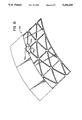
- FIG. 13 is a view similar to FIG. 2 and shows a fifth embodiment where there is an integral boss and the panel structure has a curved configuration.
- FIG. 14 is an isometric view of a single first panel section which is joined to a substantially similar (or identical) second panel section to form a sixth embodiment
- FIG. 15 is a cross-sectional view of a fifth embodiment of the present invention wherein secondary ribs are incorporated in the structure.
- FIGS. 1 through 4 A first embodiment of the present invention is shown in FIGS. 1 through 4.
- the present invention will be described as a "panel structure", with the understanding that the concept of the present invention could be incorporated in various structures which may not properly be considered as “panels”.
- An example of such structures is shown by FIG. 10.
- the panel structure 10 of the present invention is made up of first and second panel sections 12 and 14 that are bonded one to another.
- the panel sections 12 and 14 are identical or substantially identical, so only the first panel section 12 will be described in detail.
- the first panel section 12 is a single integrally formed member and for purposes of description can be considered as comprising a planar sheet portion 16, a rib portion 18, and a perimeter edge portion 20.
- the term “inner” shall denote proximity to a center plane 21 parallel to the planar sheet portions 16, and the term “outer” denotes the opposite.
- the planar sheet portion 16 extends continuously over the entire area of the panel section 12, and has an outer surface 22 and an inner surface 24.
- the rib portion 18 comprises a plurality of ribs 26, which are formed integrally with the sheet portion 16 and extend inwardly therefrom. Each rib 26 has in cross-sectional configuration (see FIG. 4) a web portion 28 which extends inwardly from the sheet portion 16 and an inner flange portion 30 at the inside edge of the web portion 28.
- the flange portion 30 has a flat inner bonding face 32 which is joined to corresponding bonding faces 32 of matching ribs of the second panel section 14 to form the finished panel structure 10 of the present invention.
- the edge portion 20 extends entirely around the perimeter of the first panel section 12 and extends from the planar sheet portion 16 in generally the same manner as the ribs 26.
- the edge portion 20 has an exterior perimeter flat surface 34 which in the present configuration is aligned at right angles with the outside surface 22 of the planar sheet portion 16, and also an inner flat bonding face 36, which in this preferred configuration lies in the same plane as the bonding faces 32 of the ribs 26.
- the interior side surface 38 of the edge portion 26 has the same general configuration as the side surfaces 40 of the ribs 26. It can readily be seen that the pattern of the arrangement and spacing of the ribs 26 and edge portion 20 of the first panel section 12 match the arrangement of the ribs 26 and edge portion 20 of the second panel 14.
- the panel structure 10 of the present invention is made by bonding the two panel sections 12 and 14 together by placing the bonding faces 32 and 36 of the ribs 26 and edge portions 20 of the two sections 12 and 14 against one another and bonding these to one another to form the finished panel structure 10.
- each of the panel sections 12 and 14, individually is substantially shown in prior art U.S. Pat. No. 4,725,334. Further, the method of manufacturing each of the panel sections 12 and 14 individually is, or may be, substantially the same as that described and shown in U.S. Pat. No. 4,113,549. However, it has been found that by joining these two individual panel sections 12 and 14 together, as described herein, there are achieved functional benefits which do not exist in a single panel section and which have not been recognized in the prior art.
- each rib has, in cross-sectional configuration, two concave side surfaces 42 having a smaller width dimension, indicated at "a". It will also be noted that the two side surfaces 44 of the flange portion 30 of each rib 26 also are moderately concave in cross-section, but that the width dimension (illustrated at "b") is greater than the width dimension of the web portion 28.
- the cross-sectional configuration of the rib 26 is, in terms of function, an I-beam, where the adjacent portion of the sheet 16 forms one flange of the I-beam, and the flange 30 is positioned on the opposite side of the web portion 28.
- the ribs 26 and the edge portion 20 act as stiffening members, and function to resist bending moments and other stresses placed on the panel sections 12.
- the ribs 26 function essentially as I-beams. Let us assume, for example, that the panel section as shown in FIG. 1 is stressed so that two opposite sides of the edge portions 20 are pushed downwardly, while the center portion of the panel section 12 remains stationary.
- each rib 26 does in fact act as an beam to provide flexural strength and stiffness to the individual panel section 12.
- each pair of upper and lower ribs 26 that are bonded to one another now reacts essentially as a single beam.
- this combined beam (made up of the upper and lower ribs 26) is subjected to a bending moment to bend the panel 10 out of its planar configuration so that the two opposite perimeter portions are pushed downwardly. The result is that the upper sheet section 16 is placed in tension, while the lower sheet section 16 is placed in compression.
- the bond line (or more precisely a bonding plane) located at 21 is in close proximity to the neutral axis of the beam 26--26 made up of the two ribs 26 that are bonded to one another.
- the material at the bond line 52 is not subjected to any significant tension or compression loads, but is subjected primarily to shear stresses.
- the bonding mechanism may have lesser strength than the parent material, without reducing the structural capacity of the panel.
- each of the two panel sections 12 and 14 are made as integral members, each of these ribs 26 is formed integrally with it adjacent sheets 16. As indicated above, the bonding is accomplished at the area which is normally subjected to the least stress.
- the first panel was designed as an isogrid structure and is essentially quite similar in structure to one of the individual panels 12 or 14, as shown in FIG. 1 of the present invention.
- the second panel was a honeycomb panel designed in accordance with preferred prior art honeycomb design criteria.
- the third panel was designed in accordance with the present invention. As indicated above the three panels were designed to have the same size and weight. The flexural stiffness of these three panels was calculated and is shown below.
- the panel 10 of the present invention does not suffer from many of the disadvantages which were cited earlier with regard to honeycomb panels.
- the first step is to begin with a blank plate which is fabricated to the desired configuration and contour. This could be accomplished by cutting the plates to the desired configuration; also it would be possible to roll it to a curved shape if desired, or otherwise forming it. Then this blank is treated to form it into one panel section 12. This can be accomplished by the chemical milling techniques described in the U.S. Patents mentioned earlier herein. Alternatively, other machining methods could be used to form the panel section 12. Then the second mating section 14 is manufactured in substantially the same manner.
- the two panel sections are then prepared for a bonding operation, and this of course will vary depending upon the bonding operation used.
- the bonding surfaces 32 and 36 should be appropriately cleaned. This could be accomplished by grinding and subsequent flash-etch chem milling. Alternatively, an electrochemical milling process could be used. Depending on the alloy or material comprising the component sections, an inter-layer could be used in the bonding process, or this bonding could be accomplished by solid state diffusion bonding.
- the two panel sections 12 and 14 are properly aligned and placed against one another, with mating bonding faces 32 and 36 being positioned against one another. It should be recognized that tooling is required to hold the mating sections in proper alignment. Then pressure is applied to the outside surfaces 22 to provide the appropriate bonding pressure sufficient to create a true metallurgical bond.
- a back pressure of argon or some other clean, inert gas is created within the structure formed by the two panel sections 12 and 14 to prevent crushing during the bonding cycle of the two panel sections 12 and 14 between the ribs.
- the pressure used to accomplish the bonding will vary.
- the finished structure has certain desirable features, some of which have been discussed previously herein. For example, problems of fatigue are substantially alleviated because of the location of the bonding area at or near the neutral axis. Also, the panel structure 10 is less susceptible to thermal problems. In applications in which a substantial temperature difference occurs from one side of a panel to the other, a thermal gradient is developed across the panel section. For typical honeycomb core panel structures, the thermal gradient tends to be greatest at the bonded interface between the core and the face. For panels of the present invention, the thermal gradient at the rib 26 to face 16 is minimized by the shape transition of the rib 26. Additionally the rib 26 is integral with the face 16 at the location of the greatest thermal gradient, thus having greater structural capacity.
- the panel structure 12 could be made of various materials, such as aluminum, nickel, titanium and alloys incorporating these metals. The dimensions of course could vary, depending upon the application. In a typical application, the sheet portion 16 could have a thickness dimension of possibly 0.020 inch, or possibly less. The rib height will vary, and this of course depends to some extent upon the feasibility of rib height relative to manufacturing techniques.
- FIGS. 5, 6 and 7. A second embodiment of the present invention is illustrated in FIGS. 5, 6 and 7.
- the second embodiment differs from the first embodiment simply in the configuration of the pattern of the ribs. It will be noted that instead of having a rectangular rib pattern, the ribs of the second embodiment are formed in a triangular pattern. Accordingly, there will not be a detailed description of this second embodiment. Rather, numerical designations of components of the first embodiment will be given to similar components of the second embodiment with an "a" suffix distinguishing those of the second embodiment.
- FIG. 9 A third embodiment of the present invention is illustrated in FIG. 9.
- the third embodiment differs from the first embodiment by having a parallel rib configuration in place of the rectangular rib configuration.
- This third embodiment is designated 10b, and it is believed that the structure and function of this third embodiment are evident from the description of the prior two embodiments. Accordingly, no detailed description will be presented herein.
- FIGS. 10, 11 and 12 A fourth embodiment of the present invention is illustrated in FIGS. 10, 11 and 12, and is designated 10c.
- the fourth embodiment differs from the previous embodiments by the incorporation in the structure of one or more integral bosses 54 to facilitate attachment of accessory components to the structure. Bosses can be incorporated into the structure without regard to rib pattern or to the bonding plane. As shown herein, this boss 54 has a circular configuration with a central through opening 56, and peripheral fastening holes 58. In FIG. 10 one panel section 12c is shown prior to being joined to the second panel section and prior to having the holes 56 and 58 formed therein.
- FIG. 13 is quite similar to FIG. 11, except that there is a triangular configuration as shown in FIGS. 5 and 6, and also except for the fact that the panel structure has a curved configuration. It is believed that the structure and function of this fifth embodiment of FIG. 13 is evident from reviewing the earlier descriptions herein, so no further description will be added. Rather, a "d" suffix will be added to distinguish the components of this fifth embodiment.
- FIGS. 14 and 15 show only a single panel, and this is formed with a central boss in the same manner as shown in FIG. 10.
- This sixth embodiment will be given numerical designation similar to the prior embodiments, with an "e" suffix distinguishing those of this sixth embodiment.
- FIG. 14 Only one panel section 14e is shown in FIG. 14, it being understood that this is to be joined to a similar panel to make a panel structure as to the prior embodiments.
- This sixth embodiment is distinguished in that in addition to the primary ribs 26e, there are provided secondary ribs 60 (see FIG. 15 which is a sectional view.) These ribs 60 are of a lower height dimension than the primary ribs 26c, and thus opposing secondary ribs 60 from the panel sections joined to one another have a gap therebetween and are not bonded to one another. These secondary ribs 60 are primarily for stiffening.
Abstract
Description
______________________________________
        Unit Flexural Stiffness - in. .sup.2 /in.
______________________________________
Panel 1   21,627
Panel 2   61,868
Panel 3   72,619
______________________________________
Claims (21)
Priority Applications (1)
| Application Number | Priority Date | Filing Date | Title |
|---|---|---|---|
| US07/716,957 US5262220A (en) | 1991-06-18 | 1991-06-18 | High strength structure assembly and method of making the same |
Applications Claiming Priority (1)
| Application Number | Priority Date | Filing Date | Title |
|---|---|---|---|
| US07/716,957 US5262220A (en) | 1991-06-18 | 1991-06-18 | High strength structure assembly and method of making the same |
Publications (1)
| Publication Number | Publication Date |
|---|---|
| US5262220A true US5262220A (en) | 1993-11-16 |
Family
ID=24880130
Family Applications (1)
| Application Number | Title | Priority Date | Filing Date |
|---|---|---|---|
| US07/716,957 Expired - Fee Related US5262220A (en) | 1991-06-18 | 1991-06-18 | High strength structure assembly and method of making the same |
Country Status (1)
| Country | Link |
|---|---|
| US (1) | US5262220A (en) |
Cited By (43)
| Publication number | Priority date | Publication date | Assignee | Title |
|---|---|---|---|---|
| US5618633A (en) * | 1994-07-12 | 1997-04-08 | Precision Castparts Corporation | Honeycomb casting |
| US5820024A (en) * | 1994-05-16 | 1998-10-13 | General Electric Company | Hollow nozzle actuating ring |
| EP0926525A2 (en) * | 1997-12-23 | 1999-06-30 | Carl Zeiss | Positioning table |
| US6213426B1 (en) | 1999-07-09 | 2001-04-10 | The Boeing Company | Monolithic structure with redundant load paths |
| WO2002055383A2 (en) * | 2000-12-12 | 2002-07-18 | Remmele Engineering, Inc. | Monolithic part and process for making the same |
| US6454211B2 (en) * | 1999-12-16 | 2002-09-24 | Airbus Deutschland Gmbh | Structural component particularly for an aircraft |
| US20020148271A1 (en) * | 2001-03-27 | 2002-10-17 | Bruno Schiavi | Process and apparatus for manufacturing products of defined thickness |
| US6619372B2 (en) | 2000-06-05 | 2003-09-16 | Eurocopter Deutschland Gmbh | Aircraft door and mold for casting the door |
| US6684593B2 (en) | 2000-02-22 | 2004-02-03 | Airbus Deutschland Gmbh | Integral structural shell component for an aircraft and method of manufacturing the same |
| US20040035979A1 (en) * | 2002-08-23 | 2004-02-26 | Mccoskey William Robert | Integrally stiffened axial load carrying skin panels for primary aircraft structure and closed loop manufacturing methods for making the same |
| US6793183B1 (en) * | 2003-04-10 | 2004-09-21 | The Boeing Company | Integral node tubular spaceframe |
| US20050097937A1 (en) * | 2000-08-17 | 2005-05-12 | Durney Max W. | Sheet material with bend controlling grooves defining a continuous web across a bend line and method for forming the same |
| US20050263645A1 (en) * | 2004-04-06 | 2005-12-01 | Kent Johnson | Structural panels for use in aircraft fuselages and other structures |
| US20060084336A1 (en) * | 1999-08-10 | 2006-04-20 | Warwick Mills, Inc. | High strength lightweight composite fabric with low gas permeability |
| FR2880403A1 (en) * | 2005-01-03 | 2006-07-07 | Pierre Favresse | Structure for e.g. table, has two rectangular shape boards made up of plastic material, where one board has network of longitudinal and transversal rigidification ribs that have transversal section opened towards another board |
| US20060226287A1 (en) * | 2004-04-06 | 2006-10-12 | Kent Grantham | Structural panels for use in aircraft fuselages and other structures |
| US20070164159A1 (en) * | 2006-01-19 | 2007-07-19 | Koch William J | Compliant crown panel for an aircraft |
| US7325771B2 (en) | 2004-09-23 | 2008-02-05 | The Boeing Company | Splice joints for composite aircraft fuselages and other structures |
| US20080121009A1 (en) * | 2000-08-17 | 2008-05-29 | Industrial Origami, Inc. | Sheet material with bend controlling displacements and method for forming the same |
| US20080149769A1 (en) * | 2006-01-19 | 2008-06-26 | The Boeing Company. | Compliant panel for aircraft |
| US20080193714A1 (en) * | 2000-08-17 | 2008-08-14 | Industrial Origami, Inc. | Method for precision bending of sheet of materials, slit sheets fabrication process |
| US20080197236A1 (en) * | 2007-02-15 | 2008-08-21 | Honeywell International Inc. | Lightweight composite material and metal thrust recovery flapper valve |
| US20080230652A1 (en) * | 2004-04-06 | 2008-09-25 | Biornstad Robert D | Composite barrel sections for aircraft fuselages and other structures, and methods and systems for manufacturing such barrel sections |
| US20080271511A1 (en) * | 2000-08-17 | 2008-11-06 | Industrial Origami, Inc. | Sheet material with bend controlling displacements and method for forming the same |
| US7503368B2 (en) | 2004-11-24 | 2009-03-17 | The Boeing Company | Composite sections for aircraft fuselages and other structures, and methods and systems for manufacturing such sections |
| FR2927686A1 (en) * | 2008-02-20 | 2009-08-21 | Eads Socata Sa | MONOLITHIC COMPOSITE PANEL SELF-RAIDI AND SWIVEL, IN PARTICULAR FOR A MOBILE AIRCRAFT PART. |
| US20090280348A1 (en) * | 2006-09-11 | 2009-11-12 | Thyssenkrupp Steel Ag | Structured composite sheet |
| US20090320398A1 (en) * | 2008-06-30 | 2009-12-31 | Gouvea Roberto Paton | Monolithic integrated structural panels especially useful for aircraft structures and methods of making the same |
| WO2010049419A2 (en) * | 2008-10-31 | 2010-05-06 | Inter Ikea Systems B.V. [Nl] | Board product, and manufacturing method thereof |
| US20100122563A1 (en) * | 2008-11-16 | 2010-05-20 | Industrial Origami, Inc. | Method and apparatus for forming bend-controlling straps in sheet material |
| US8042767B2 (en) | 2007-09-04 | 2011-10-25 | The Boeing Company | Composite fabric with rigid member structure |
| US20110290940A1 (en) * | 2010-04-30 | 2011-12-01 | Airbus Operations Gmbh | Pressure bulkhead for purposes of arrangement in an aircraft fuselage |
| US8114524B2 (en) | 2002-09-26 | 2012-02-14 | Industrial Origami, Inc. | Precision-folded, high strength, fatigue-resistant structures and sheet therefor |
| US20120187246A1 (en) * | 2011-01-21 | 2012-07-26 | Mitsubishi Aircraft Corporation | Vent stringer and aircraft main wing |
| CN102616365A (en) * | 2011-01-31 | 2012-08-01 | 空中客车运营简化股份公司 | Stiffened structure integrating an opening |
| US8388795B2 (en) | 2007-05-17 | 2013-03-05 | The Boeing Company | Nanotube-enhanced interlayers for composite structures |
| US8438893B2 (en) | 2006-10-26 | 2013-05-14 | Industrial Origami, Inc. | Method of forming two-dimensional sheet material into three-dimensional structure |
| US8505258B2 (en) | 2000-08-17 | 2013-08-13 | Industrial Origami, Inc. | Load-bearing three-dimensional structure |
| US20140299713A1 (en) * | 2011-12-27 | 2014-10-09 | Mitsubishi Aircraft Corporation | Vent member, wing panel, and main wing for aircraft |
| US8936164B2 (en) | 2012-07-06 | 2015-01-20 | Industrial Origami, Inc. | Solar panel rack |
| US10926857B2 (en) | 2016-06-17 | 2021-02-23 | The Boeing Company | Pressurized bulkhead |
| FR3101611A1 (en) * | 2019-10-02 | 2021-04-09 | Airbus Operations (S.A.S.) | Reinforced panel with a honeycomb structure comprising at least one connection zone having an extra thickness and aircraft comprising at least one such reinforced panel |
| US20220016834A1 (en) * | 2020-07-15 | 2022-01-20 | Spirit Aerosystems, Inc. | Method of manufacturing folded structure with additive features |
Citations (4)
| Publication number | Priority date | Publication date | Assignee | Title |
|---|---|---|---|---|
| US3533153A (en) * | 1967-08-24 | 1970-10-13 | North American Rockwell | Method of fabricating sandwich-type structures |
| US4113549A (en) * | 1977-04-06 | 1978-09-12 | Chem-Tronics, Inc. | Chemical milling process |
| US4406393A (en) * | 1981-03-23 | 1983-09-27 | Rockwell International Corporation | Method of making filamentary reinforced metallic structures |
| US4725334A (en) * | 1985-05-15 | 1988-02-16 | Chem-Tronics, Inc. | Method of forming integrally stiffened structures |
-
1991
- 1991-06-18 US US07/716,957 patent/US5262220A/en not_active Expired - Fee Related
Patent Citations (5)
| Publication number | Priority date | Publication date | Assignee | Title |
|---|---|---|---|---|
| US3533153A (en) * | 1967-08-24 | 1970-10-13 | North American Rockwell | Method of fabricating sandwich-type structures |
| US4113549A (en) * | 1977-04-06 | 1978-09-12 | Chem-Tronics, Inc. | Chemical milling process |
| US4137118A (en) * | 1977-04-06 | 1979-01-30 | Chem-Tronics, Inc. | Chemical milling apparatus |
| US4406393A (en) * | 1981-03-23 | 1983-09-27 | Rockwell International Corporation | Method of making filamentary reinforced metallic structures |
| US4725334A (en) * | 1985-05-15 | 1988-02-16 | Chem-Tronics, Inc. | Method of forming integrally stiffened structures |
Non-Patent Citations (1)
| Title |
|---|
| Microsandwich Honeycomb/appearing SAMPE Journal, vol. 25, No. 3, May/Jun. 1989 by T. Balakrishna Bhat, Taylor Wang and Lorna Gibson. * |
Cited By (95)
| Publication number | Priority date | Publication date | Assignee | Title |
|---|---|---|---|---|
| US5820024A (en) * | 1994-05-16 | 1998-10-13 | General Electric Company | Hollow nozzle actuating ring |
| US5618633A (en) * | 1994-07-12 | 1997-04-08 | Precision Castparts Corporation | Honeycomb casting |
| EP0926525A2 (en) * | 1997-12-23 | 1999-06-30 | Carl Zeiss | Positioning table |
| EP0926525A3 (en) * | 1997-12-23 | 2000-01-12 | Carl Zeiss | Positioning table |
| US6111691A (en) * | 1997-12-23 | 2000-08-29 | Carl-Zeiss-Stiftung | Positioning table |
| US6443392B2 (en) | 1999-07-09 | 2002-09-03 | The Boeing Company | Monolithic structure with redundant load paths |
| US6213426B1 (en) | 1999-07-09 | 2001-04-10 | The Boeing Company | Monolithic structure with redundant load paths |
| US20060084336A1 (en) * | 1999-08-10 | 2006-04-20 | Warwick Mills, Inc. | High strength lightweight composite fabric with low gas permeability |
| US6454211B2 (en) * | 1999-12-16 | 2002-09-24 | Airbus Deutschland Gmbh | Structural component particularly for an aircraft |
| EP1108646A3 (en) * | 1999-12-16 | 2002-12-18 | Airbus Deutschland GmbH | Structural component |
| US6684593B2 (en) | 2000-02-22 | 2004-02-03 | Airbus Deutschland Gmbh | Integral structural shell component for an aircraft and method of manufacturing the same |
| US6619372B2 (en) | 2000-06-05 | 2003-09-16 | Eurocopter Deutschland Gmbh | Aircraft door and mold for casting the door |
| US8505258B2 (en) | 2000-08-17 | 2013-08-13 | Industrial Origami, Inc. | Load-bearing three-dimensional structure |
| US20080063834A1 (en) * | 2000-08-17 | 2008-03-13 | Industrial Origami, Inc. | Sheet Material with Bend Controlling Grooves Defining a Continuous Web Across a Bend Line and Method for Forming the Same |
| US20080193714A1 (en) * | 2000-08-17 | 2008-08-14 | Industrial Origami, Inc. | Method for precision bending of sheet of materials, slit sheets fabrication process |
| US20080271511A1 (en) * | 2000-08-17 | 2008-11-06 | Industrial Origami, Inc. | Sheet material with bend controlling displacements and method for forming the same |
| US7560155B2 (en) | 2000-08-17 | 2009-07-14 | Industrial Origami, Inc. | Sheet material with bend controlling grooves defining a continuous web across a bend line and method for forming the same |
| US20080121009A1 (en) * | 2000-08-17 | 2008-05-29 | Industrial Origami, Inc. | Sheet material with bend controlling displacements and method for forming the same |
| US20050097937A1 (en) * | 2000-08-17 | 2005-05-12 | Durney Max W. | Sheet material with bend controlling grooves defining a continuous web across a bend line and method for forming the same |
| US7263869B2 (en) * | 2000-08-17 | 2007-09-04 | Industrial Origami, Inc. | Method for forming sheet material with bend controlling grooves defining a continuous web across a bend line |
| EP1343609A4 (en) * | 2000-12-12 | 2007-10-03 | Remmele Engineering Inc | Monolithic part and process for making the same |
| US6973815B2 (en) | 2000-12-12 | 2005-12-13 | Remmele Engineering, Inc. | Monolithic part and process for making the same |
| WO2002055383A2 (en) * | 2000-12-12 | 2002-07-18 | Remmele Engineering, Inc. | Monolithic part and process for making the same |
| WO2002055383A3 (en) * | 2000-12-12 | 2002-10-03 | Remmele Engineering Inc | Monolithic part and process for making the same |
| US20040101655A1 (en) * | 2000-12-12 | 2004-05-27 | Bryans Philip R. | Monolithic part and process for making the same |
| EP1343609A2 (en) * | 2000-12-12 | 2003-09-17 | Remmele Engineering Inc. | Monolithic part and process for making the same |
| US20020148271A1 (en) * | 2001-03-27 | 2002-10-17 | Bruno Schiavi | Process and apparatus for manufacturing products of defined thickness |
| US20040035979A1 (en) * | 2002-08-23 | 2004-02-26 | Mccoskey William Robert | Integrally stiffened axial load carrying skin panels for primary aircraft structure and closed loop manufacturing methods for making the same |
| US8114524B2 (en) | 2002-09-26 | 2012-02-14 | Industrial Origami, Inc. | Precision-folded, high strength, fatigue-resistant structures and sheet therefor |
| US8377566B2 (en) | 2002-09-26 | 2013-02-19 | Industrial Origami, Inc. | Precision-folded, high strength, fatigue-resistant structures and sheet therefor |
| US6793183B1 (en) * | 2003-04-10 | 2004-09-21 | The Boeing Company | Integral node tubular spaceframe |
| US7527222B2 (en) | 2004-04-06 | 2009-05-05 | The Boeing Company | Composite barrel sections for aircraft fuselages and other structures, and methods and systems for manufacturing such barrel sections |
| US20060226287A1 (en) * | 2004-04-06 | 2006-10-12 | Kent Grantham | Structural panels for use in aircraft fuselages and other structures |
| US8157212B2 (en) | 2004-04-06 | 2012-04-17 | The Boeing Company | Composite barrel sections for aircraft fuselages and other structures, and methods and systems for manufacturing such barrel sections |
| US8182628B2 (en) | 2004-04-06 | 2012-05-22 | The Boeing Company | Composite barrel sections for aircraft fuselages and other structures, and methods for systems for manufacturing such barrel sections |
| US20100223772A1 (en) * | 2004-04-06 | 2010-09-09 | The Boeing Company | Structural Panels for Use in Aircraft Fuselages and Other Structures |
| US20080230652A1 (en) * | 2004-04-06 | 2008-09-25 | Biornstad Robert D | Composite barrel sections for aircraft fuselages and other structures, and methods and systems for manufacturing such barrel sections |
| US7159822B2 (en) | 2004-04-06 | 2007-01-09 | The Boeing Company | Structural panels for use in aircraft fuselages and other structures |
| US20050263645A1 (en) * | 2004-04-06 | 2005-12-01 | Kent Johnson | Structural panels for use in aircraft fuselages and other structures |
| US8382037B2 (en) | 2004-04-06 | 2013-02-26 | The Boeing Company | Composite barrel sections for aircraft fuselages and other structures |
| US7134629B2 (en) * | 2004-04-06 | 2006-11-14 | The Boeing Company | Structural panels for use in aircraft fuselages and other structures |
| US7716835B2 (en) | 2004-04-06 | 2010-05-18 | The Boeing Company | Methods of manufacturing structural panels |
| US8496206B2 (en) | 2004-04-06 | 2013-07-30 | The Boeing Company | Structural panels for use in aircraft fuselages and other structures |
| WO2006036462A3 (en) * | 2004-08-31 | 2006-11-23 | Ind Origami Llc | Bend line with bend controlling grooves and method |
| US7325771B2 (en) | 2004-09-23 | 2008-02-05 | The Boeing Company | Splice joints for composite aircraft fuselages and other structures |
| US8869403B2 (en) | 2004-09-23 | 2014-10-28 | The Boeing Company | Splice joints for composite aircraft fuselages and other structures |
| US8882040B2 (en) | 2004-09-23 | 2014-11-11 | The Boeing Company | Splice joints for composite aircraft fuselages and other structures |
| US10689086B2 (en) | 2004-09-23 | 2020-06-23 | The Boeing Company | Splice joints for composite aircraft fuselages and other structures |
| US9738371B2 (en) | 2004-09-23 | 2017-08-22 | The Boeing Company | Splice joints for composite aircraft fuselages and other structures |
| US8061035B2 (en) | 2004-09-23 | 2011-11-22 | The Boeing Company | Splice joints for composite aircraft fuselages and other structures |
| US8418740B2 (en) | 2004-11-24 | 2013-04-16 | The Boeing Company | Composite sections for aircraft fuselages and other structures, and methods and systems for manufacturing such sections |
| US7503368B2 (en) | 2004-11-24 | 2009-03-17 | The Boeing Company | Composite sections for aircraft fuselages and other structures, and methods and systems for manufacturing such sections |
| US8303758B2 (en) | 2004-11-24 | 2012-11-06 | The Boeing Company | Methods for manufacturing composite sections for aircraft fuselages and other structures |
| US8168023B2 (en) | 2004-11-24 | 2012-05-01 | The Boeing Company | Composite sections for aircraft fuselages and other structures, and methods and systems for manufacturing such sections |
| FR2880403A1 (en) * | 2005-01-03 | 2006-07-07 | Pierre Favresse | Structure for e.g. table, has two rectangular shape boards made up of plastic material, where one board has network of longitudinal and transversal rigidification ribs that have transversal section opened towards another board |
| US8398021B2 (en) * | 2006-01-19 | 2013-03-19 | The Boeing Company | Compliant crown panel for an aircraft |
| US20080149769A1 (en) * | 2006-01-19 | 2008-06-26 | The Boeing Company. | Compliant panel for aircraft |
| US20070164159A1 (en) * | 2006-01-19 | 2007-07-19 | Koch William J | Compliant crown panel for an aircraft |
| US8434716B2 (en) * | 2006-01-19 | 2013-05-07 | The Boeing Company | Compliant crown panel for an aircraft |
| US7997529B2 (en) * | 2006-01-19 | 2011-08-16 | The Boeing Company | Compliant panel for aircraft |
| US20110101164A1 (en) * | 2006-01-19 | 2011-05-05 | The Boeing Company | Compliant crown panel for an aircraft |
| US8980397B2 (en) * | 2006-09-11 | 2015-03-17 | Thyssenkrupp Steel Europe Ag | Structured composite sheet |
| US20090280348A1 (en) * | 2006-09-11 | 2009-11-12 | Thyssenkrupp Steel Ag | Structured composite sheet |
| US8438893B2 (en) | 2006-10-26 | 2013-05-14 | Industrial Origami, Inc. | Method of forming two-dimensional sheet material into three-dimensional structure |
| US20080197236A1 (en) * | 2007-02-15 | 2008-08-21 | Honeywell International Inc. | Lightweight composite material and metal thrust recovery flapper valve |
| US8657990B2 (en) | 2007-05-17 | 2014-02-25 | The Boeing Company | Nanotube-enhanced interlayers for composite structures |
| US8388795B2 (en) | 2007-05-17 | 2013-03-05 | The Boeing Company | Nanotube-enhanced interlayers for composite structures |
| US8042767B2 (en) | 2007-09-04 | 2011-10-25 | The Boeing Company | Composite fabric with rigid member structure |
| US8728263B2 (en) | 2007-09-04 | 2014-05-20 | The Boeing Company | Composite fabric with rigid member structure |
| WO2009112735A1 (en) * | 2008-02-20 | 2009-09-17 | Socata | Unitary, self-stiffened, and pivoting composite panel, in particular for a mobile part of an aircraft |
| FR2927686A1 (en) * | 2008-02-20 | 2009-08-21 | Eads Socata Sa | MONOLITHIC COMPOSITE PANEL SELF-RAIDI AND SWIVEL, IN PARTICULAR FOR A MOBILE AIRCRAFT PART. |
| US20100320331A1 (en) * | 2008-02-20 | 2010-12-23 | Socata | Unitary, Self-Stiffened and Pivoting Composite Panel, in Particular for a Mobile Part of an Aircraft |
| US8079549B2 (en) * | 2008-06-30 | 2011-12-20 | EMBRAER—Empresa Brasileira de Aeronautica S.A. | Monolithic integrated structural panels especially useful for aircraft structures |
| US20090320398A1 (en) * | 2008-06-30 | 2009-12-31 | Gouvea Roberto Paton | Monolithic integrated structural panels especially useful for aircraft structures and methods of making the same |
| WO2010049419A2 (en) * | 2008-10-31 | 2010-05-06 | Inter Ikea Systems B.V. [Nl] | Board product, and manufacturing method thereof |
| WO2010049419A3 (en) * | 2008-10-31 | 2010-07-01 | Inter Ikea Systems B.V. [Nl] | Board product, and manufacturing method thereof |
| US20100122563A1 (en) * | 2008-11-16 | 2010-05-20 | Industrial Origami, Inc. | Method and apparatus for forming bend-controlling straps in sheet material |
| US8596578B2 (en) * | 2010-04-30 | 2013-12-03 | Airbus Operations Gmbh | Pressure bulkhead for purposes of arrangement in an aircraft fuselage |
| US20110290940A1 (en) * | 2010-04-30 | 2011-12-01 | Airbus Operations Gmbh | Pressure bulkhead for purposes of arrangement in an aircraft fuselage |
| US20120187246A1 (en) * | 2011-01-21 | 2012-07-26 | Mitsubishi Aircraft Corporation | Vent stringer and aircraft main wing |
| US8672269B2 (en) * | 2011-01-21 | 2014-03-18 | Mitsubishi Aircraft Corporation | Vent stringer and aircraft main wing |
| CN102616365B (en) * | 2011-01-31 | 2016-08-03 | 空中客车运营简化股份公司 | The enhancing structure of integral finish |
| US8840980B2 (en) | 2011-01-31 | 2014-09-23 | Airbus Operations Sas | Stiffened structure integrating an opening |
| EP2481667A1 (en) * | 2011-01-31 | 2012-08-01 | Airbus Opérations SAS | Stiffened structure including an opening |
| CN102616365A (en) * | 2011-01-31 | 2012-08-01 | 空中客车运营简化股份公司 | Stiffened structure integrating an opening |
| FR2970941A1 (en) * | 2011-01-31 | 2012-08-03 | Airbus Operations Sas | RAIDIE STRUCTURE INTEGRATING AN ORIFICE |
| US9926082B2 (en) * | 2011-12-27 | 2018-03-27 | Mitsubishi Aircraft Corporation | Vent member, wing panel, and main wing for aircraft |
| US20140299713A1 (en) * | 2011-12-27 | 2014-10-09 | Mitsubishi Aircraft Corporation | Vent member, wing panel, and main wing for aircraft |
| US9425731B2 (en) | 2012-07-06 | 2016-08-23 | Industrial Origami, Inc. | Solar panel rack |
| US9166521B2 (en) * | 2012-07-06 | 2015-10-20 | Industrial Origami, Inc. | Solar panel rack |
| US8936164B2 (en) | 2012-07-06 | 2015-01-20 | Industrial Origami, Inc. | Solar panel rack |
| US10926857B2 (en) | 2016-06-17 | 2021-02-23 | The Boeing Company | Pressurized bulkhead |
| FR3101611A1 (en) * | 2019-10-02 | 2021-04-09 | Airbus Operations (S.A.S.) | Reinforced panel with a honeycomb structure comprising at least one connection zone having an extra thickness and aircraft comprising at least one such reinforced panel |
| US20220016834A1 (en) * | 2020-07-15 | 2022-01-20 | Spirit Aerosystems, Inc. | Method of manufacturing folded structure with additive features |
| US11766828B2 (en) * | 2020-07-15 | 2023-09-26 | Spirit Aerosystems, Inc. | Method of manufacturing folded structure with additive features |
Similar Documents
| Publication | Publication Date | Title |
|---|---|---|
| US5262220A (en) | High strength structure assembly and method of making the same | |
| US5451472A (en) | Multiple density sandwich structures and method of fabrication | |
| US4223053A (en) | Truss core panels | |
| US5951800A (en) | Fiber/metal laminate splice | |
| US4769968A (en) | Truss-core corrugation for compressive loads | |
| US6871725B2 (en) | Honeycomb core acoustic unit with metallurgically secured deformable septum, and method of manufacture | |
| US6064352A (en) | Composite isogrid structures for parabolic surfaces | |
| US4549685A (en) | Method for superplastic forming and diffusion bonding Y shaped support structures | |
| US2720948A (en) | Honeycomb panel constructed for bolting or riveting to framework or another panel | |
| JP2002053098A (en) | Structural member for airplane, manufacturing method thereof and reinforcement deformed member for the structural member | |
| US20160311514A1 (en) | Lightweight structural panel | |
| KR19980070687A (en) | Molded parts with band-like overlapping plate | |
| US5118571A (en) | Structure and method for forming structural components | |
| US2960197A (en) | Sandwich structure | |
| US7124982B2 (en) | Device for bracing a shell in an aircraft fuselage | |
| US4588651A (en) | Accordion expansion process | |
| US5567535A (en) | Fiber/metal laminate splice | |
| GB2182703A (en) | Improvements relating to structural sandwich sheet material comprising two face sheets and two core sheets | |
| CA2438417C (en) | Lightweight structural component made of metallic ply materials | |
| US5401583A (en) | Gas manifolding for super plastic forming and diffusion bonding of truss core sandwiches | |
| US4801070A (en) | Engine duct and case construction | |
| US4422569A (en) | Forming metal articles | |
| GB2109711A (en) | Method for superplastic forming and diffusion bonding complex continuous structures | |
| US5927138A (en) | Method of forming a structural member from tubular material | |
| US4577798A (en) | Method of fabricating expanded sandwich panels having an enclosed core |
Legal Events
| Date | Code | Title | Description |
|---|---|---|---|
| AS | Assignment |
Owner name: CHEMICAL BANK Free format text: SECURITY INTEREST;ASSIGNOR:CERTAIN SUBSIDIARIES OF THE INTERLAKE CORPORATION: THE INTERLAKE COMPANIES, INC. CHEMTRONICS, INC.;REEL/FRAME:006296/0923 Effective date: 19920817 |
|
| AS | Assignment |
Owner name: CHEM-TRONICS, INC., CALIFORNIA Free format text: ASSIGNMENT OF ASSIGNORS INTEREST.;ASSIGNORS:SPRIGGS, DONALD R.;TAFT, WILLIAM G.;LOEDEL, CHRISTIAN W.;REEL/FRAME:006478/0889;SIGNING DATES FROM 19910627 TO 19910709 |
|
| REMI | Maintenance fee reminder mailed | ||
| LAPS | Lapse for failure to pay maintenance fees | ||
| FP | Lapsed due to failure to pay maintenance fee |
Effective date: 19971119 |
|
| STCH | Information on status: patent discontinuation |
Free format text: PATENT EXPIRED DUE TO NONPAYMENT OF MAINTENANCE FEES UNDER 37 CFR 1.362 |