US5262976A - Plural-bit recoding multiplier - Google Patents
Plural-bit recoding multiplier Download PDFInfo
- Publication number
- US5262976A US5262976A US07/973,932 US97393292A US5262976A US 5262976 A US5262976 A US 5262976A US 97393292 A US97393292 A US 97393292A US 5262976 A US5262976 A US 5262976A
- Authority
- US
- United States
- Prior art keywords
- multiplier
- sub
- multiplicand
- complement
- bit
- Prior art date
- Legal status (The legal status is an assumption and is not a legal conclusion. Google has not performed a legal analysis and makes no representation as to the accuracy of the status listed.)
- Expired - Lifetime
Links
Images


Classifications
-
- G—PHYSICS
- G06—COMPUTING; CALCULATING OR COUNTING
- G06F—ELECTRIC DIGITAL DATA PROCESSING
- G06F7/00—Methods or arrangements for processing data by operating upon the order or content of the data handled
- G06F7/38—Methods or arrangements for performing computations using exclusively denominational number representation, e.g. using binary, ternary, decimal representation
- G06F7/48—Methods or arrangements for performing computations using exclusively denominational number representation, e.g. using binary, ternary, decimal representation using non-contact-making devices, e.g. tube, solid state device; using unspecified devices
- G06F7/52—Multiplying; Dividing
- G06F7/523—Multiplying only
- G06F7/533—Reduction of the number of iteration steps or stages, e.g. using the Booth algorithm, log-sum, odd-even
- G06F7/5334—Reduction of the number of iteration steps or stages, e.g. using the Booth algorithm, log-sum, odd-even by using multiple bit scanning, i.e. by decoding groups of successive multiplier bits in order to select an appropriate precalculated multiple of the multiplicand as a partial product
- G06F7/5336—Reduction of the number of iteration steps or stages, e.g. using the Booth algorithm, log-sum, odd-even by using multiple bit scanning, i.e. by decoding groups of successive multiplier bits in order to select an appropriate precalculated multiple of the multiplicand as a partial product overlapped, i.e. with successive bitgroups sharing one or more bits being recoded into signed digit representation, e.g. using the Modified Booth Algorithm
- G06F7/5338—Reduction of the number of iteration steps or stages, e.g. using the Booth algorithm, log-sum, odd-even by using multiple bit scanning, i.e. by decoding groups of successive multiplier bits in order to select an appropriate precalculated multiple of the multiplicand as a partial product overlapped, i.e. with successive bitgroups sharing one or more bits being recoded into signed digit representation, e.g. using the Modified Booth Algorithm each bitgroup having two new bits, e.g. 2nd order MBA
-
- G—PHYSICS
- G06—COMPUTING; CALCULATING OR COUNTING
- G06F—ELECTRIC DIGITAL DATA PROCESSING
- G06F7/00—Methods or arrangements for processing data by operating upon the order or content of the data handled
- G06F7/38—Methods or arrangements for performing computations using exclusively denominational number representation, e.g. using binary, ternary, decimal representation
- G06F7/48—Methods or arrangements for performing computations using exclusively denominational number representation, e.g. using binary, ternary, decimal representation using non-contact-making devices, e.g. tube, solid state device; using unspecified devices
- G06F7/4806—Computations with complex numbers
- G06F7/4812—Complex multiplication
-
- G—PHYSICS
- G06—COMPUTING; CALCULATING OR COUNTING
- G06F—ELECTRIC DIGITAL DATA PROCESSING
- G06F7/00—Methods or arrangements for processing data by operating upon the order or content of the data handled
- G06F7/38—Methods or arrangements for performing computations using exclusively denominational number representation, e.g. using binary, ternary, decimal representation
- G06F7/48—Methods or arrangements for performing computations using exclusively denominational number representation, e.g. using binary, ternary, decimal representation using non-contact-making devices, e.g. tube, solid state device; using unspecified devices
- G06F7/544—Methods or arrangements for performing computations using exclusively denominational number representation, e.g. using binary, ternary, decimal representation using non-contact-making devices, e.g. tube, solid state device; using unspecified devices for evaluating functions by calculation
- G06F7/5443—Sum of products
-
- G—PHYSICS
- G06—COMPUTING; CALCULATING OR COUNTING
- G06F—ELECTRIC DIGITAL DATA PROCESSING
- G06F7/00—Methods or arrangements for processing data by operating upon the order or content of the data handled
- G06F7/38—Methods or arrangements for performing computations using exclusively denominational number representation, e.g. using binary, ternary, decimal representation
- G06F7/48—Methods or arrangements for performing computations using exclusively denominational number representation, e.g. using binary, ternary, decimal representation using non-contact-making devices, e.g. tube, solid state device; using unspecified devices
- G06F7/499—Denomination or exception handling, e.g. rounding or overflow
- G06F7/49994—Sign extension
Definitions
- the present invention relates generally to binary multipliers and more specifically to an improved speed binary multiplier capable of multiplying signed and unsigned operands.
- the first three partial products are performed with sign extension.
- the fourth partial product which is the sign bit, is converted to a two's complement notation before addition with the other partial products. This is to correct for the negative sign bit in combination with the sign extension.
- Booth algorithms compared to the present invention, introduces not only extra delays caused by a more complex Booth Decoder, but also results in increased circuit size due to the need of propagating the sign extension through the CSA (Carry Save Adder) array. This also leads to poorer time performance.
- CSA Carry Save Adder
- the original Booth algorithm and the modified Booth algorithm involve searching for and determining strings of zeros or ones in the multiplier and performing addition and subtraction for the different partial products depending upon a determination of the beginning, end or middle of the string.
- a relative 1-digit shift always occurs between the multiplicand and the partial sum, regardless of whether an addition has occurred or not.
- Booth's algorithm permits more than one shift at a time, depending on the grouping of ones and zeros in the multiplier bit by bit, starting with the LSB, shifting the partial product relative to the multiplicand as each bit is examined. Subtract the multiplicand from the partial product when you find the first one in a string of ones. Similarly, upon finding the first zero in a string of zeros, add the multiplicand to the partial product. Perform no operation when the bit examined is identical to the previous multiplier bit.
- a modified version of Booth's algorithm is more commonly used.
- the difference between the Booth's and the modified Booth's algorithm is as follows:
- the modified Booth always generates m/2 independent partial products, whereas the original Booth generates a varying (at most m/2) number of partial products, depending on the bit pattern of the multiplier.
- parallel hardware implementation lends itself only to the fixed independent number of partial products.
- the modified multiplier encoding scheme encodes 2-bit groups and produces five partial products for an 8-bit multiplier, the fifth partial product being a consequence of the fact that the algorithm only handles two's complement numbers.
- the most conventional modified Booth scheme is to consider a bit-pair in each step, i.e., bit-pair recoding.
- the multiplier bits are divided into 2-bit pairs, and 3 bits (a triplet) are scanned at a time, two-bits form the present pair and the third bit (the overlap bit) from the high-order bit of the adjacent lower-order pair.
- the algorithm converts them into a set of 5 signed digits 0, +1, +2, -1 and -2. According to the Boolean truth table shown in Table 3, each recoded digit performs only a simplified processing on the multiplicand, such as add, subtract, or shift.
- State-of-the-art multipliers such as those employed in DSP (Digital Signal Processing) architectures, should also be capable of performing accumulation of the products, as well as be capable of operating on both unsigned integers and two's complemented binary words.
- Another object of the present invention is to provide an recoding scheme which is capable of handling signed and unsigned numbers without substantial pre-conditioning.
- a still further object of the present invention is to provide a sign extension requiring less hardware.
- a still further object of the present invention is to reduce the size of the adder array by selective pre-addition.
- a still further object of the present invention is to provide a multiplier/accumulator with product sign extension.
- Still an even further object of the present invention is to provide improved mechanisms for taking two's complements of multiplicands and multipliers as well as converting sign magnitude numbers to two's complements.
- An even further object of the present invention is to provide an improved complex multiplier requiring fewer registers and multiplexers.
- a recoding system wherein for two-bit pairs.
- the set of signed digits is reduced from five to four which includes zero.
- Recoding scheme by special recoding and control of Carry of the most significant bit allows the recoding scheme to accommodate negative two's complement multipliers.
- the recoding scheme can operate in two-bit, three-bit, four-bit groups etc. For the three-bit, only two additional signed digits are used whereas for a four-bit recoding scheme four additional sign bits are used.
- the Carryout of the three-bit and four-bit recoding scheme is independent of Carryin.
- the sign extension of the partial products is improved by using a single sign extension word for all the sign extensions.
- the sign extension word SEW is formed as a plurality of negative bits (1) beginning with the sign bit of the first negative partial product and extending the length of the multiplier, except for a positive sign bit (0) for a sign bit of subsequent negative partial products substituted for the corresponding negative bit of the sign extension word SEW.
- the single sign word SEW is produced by determining and collecting sign bits SE of the partial products as a sign word and two's complementing the sign word to produce the sign extension word SEW.
- the number of partial products using the recoded multiplier requires an additional or carry partial product for the Carryout of most significant recoded group. If this extra partial product is negative, the complementing includes adding a complementing Carry. Also as previously discussed, the sign extension word is a complemented operation and therefore a complementing Carry must be added to it also. To reduce the size of the array, the present scheme determines the position of the complementing Carry for the sign extension word and the occurrence of a complementing Carry for the additional partial product and pre-adds these two Carries to the multiplicand of one of the partial products prior to the array. This value is then held until needed. This operation is performed in parallel with the multiplier recording means.
- the output of the adder array is a sum S and a Carry C of N bits and the sign must be extended to the capacity of the accumulator register.
- the present multiplier/accumulator produces a product sign extension word PSEW as a function of the multiplicand and multiplier to extend the sum S and the Carry C to the length of the accumulator.
- the product sign extension word PSEW is produced in parallel with the partial products and the adder array.
- a final adder adds the sum S the Carry C, the product sign extension word PSEW and the most significant bits of the accumulator register.
- the final adder includes merging capability for merging the sum S, the Carry C, the sign produce extension word and the most significant bits into two merge words and a simple adder for adding the two merge words.
- the product sign extension word PSEW is uniquely selected between two possible alternatives so as to merge with the sum S, Carry C and the most significant bits of the accumulator register.
- the least significant bit of the product sign extension word PSEW can have a one or zero.
- the formation of a two's complement may be by adding a one to the one's complement as follows: ##EQU1## or by adding the complement of the first bit to the one's complement of the remaining bits with the first bit uncomplemented as follows: ##EQU2##
- the complement Carry being either the one or A 0 will be provided in the same place in the adder array.
- the selectivity of which method depends upon the position of the partial product produced by the recoded multiplier. If a recoded multiplier is two, the first method is used and if the recoded multiplier is one, the second method is used.
- the ability to select the method of complementing allows the present system to handle signed magnitude numbers without any substantial processing.
- the absolute value is stored in the multiplicand register as a one's complement. Whether the Q or Q output of the register is selected is a function of a negative or positive partial product and will only require providing a appropriate complementing Carry. This is the only processing needed.
- the one's complement of the absolute value of the multiplier can be provided in the multiplier register and a one is added to the least significant bit during the recoding process.
- the multiplier includes a complementor performing two's complements of the multiplicand by loading the multiplicand or the one's complement of the multiplicand into the multiplicand, register depending upon the input format of the multiplicand multiplier and output format of the product.
- the complementor forms the two's complement by adding a complementing carry if the multiplicand was loaded as a one's complement in the multiplicand register and the recoded multiplier group is positive.
- the complementor also forms two's complement by adding a complementing carry if the multiplicand was loaded uncomplemented into the multiplicand register and the recoded multiplier group is negative. The storing of the one's complement of the negative multiplicand into the multiplicand register allows this reversal to take place.
- the ability to perform the two's complement of a number for a positive or negative partial products reduces the hardware needed in a complex multiplier for multiplying complex numbers (A+jB) and (C+jB).
- the structure requires four registers with four partial product multiplexers with preadders and a pair of adder arrays.
- FIG. 1 is a block diagram of a multiplier according the principles of the present invention.
- FIG. 2 is a logic diagram of a recoder according to principles of the present invention.
- FIG. 3 is a logic diagram of the first partial product P 0 multiplexer according to the principles of the present invention.
- FIG. 4 is other multiplexers for partial products P 1 P 2 according to the principles of the present invention.
- FIG. 5 is a logic diagram of an extra product P 4 multiplexer including a pre-adder according the principles of the present invention.
- FIG. 6 is a logic diagram of a sign extension multiplexer according to the principles of the present invention.
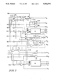
- FIG. 7 is a block diagram illustrating a complex multiplier according to the principles of the present invention.
- FIG. 8 is a block diagram of a multiplier/accumulator according to the principles of the present invention.
- FIGS. 8a and 8b are modification of the accumulator portion of FIG. 8 using piplining according to the principles the present invention.
- FIGS. 9a and 9b are logic block diagrams of X and Y multiplexers for a four-bit decoder according the principles of the present invention.
- FIGS. 10a and 10b are logic block diagrams of alternative X and Y multiplexers for a four-bit recoder scheme according to the principles of the present invention.
- FIG. 11 is a logic diagram of a four-bit recoder according to the principles of the present invention.
- FIGS. 12a and 12b are logic diagrams of the partial product complementing carry control according to the principles of the present invention.
- FIG. 1 shows a multiplier 10 according to the present invention including an input port 12 for the multiplicand A, input port 14 for the multiplicand format control TCA, input port 16 for the multiplier B, and input port 18 for the multiplier format control TCB.
- TCA and TCB stand for Two's Complement Format which are a zero when the numbers are unsigned numbers or 1 when the numbers are two's complement numbers.
- the input port 12 for the multiplicand A is connected to a multiplicand register 20 and to a pre-adder 30.
- the multiplicand format controls port 14 is also connected to the pre-adder 30.
- the multiplier port 16 and the multiplier format control port 18 are both connected to a recoder 50.
- the output of the recoder 50 is connected to a multiplier register 60 and to the pre-adder 30 and the output of the pre-adder 30 is connected to the pre-adder register 40.
- a multiplexer array 70 receives inputs from the output of the multiplicand register 20, the pre-adder register 40 and the recoded multiplier register 60.
- the recoded multiplier register 60 provides the controls for the multiplexer array 70.
- the output of the multiplexer array 70 are partial products which are provided to adder array 80 which may be for example a Wallace Tree, although other arrays may be provided.
- the output of the adder array 80 which, are generally a Carry and a Sum, are added in a final adder 90 which provides a final product at output port 92.
- the recoder 50 recodes two or more bits groupings of the multiplier so as to limit the set of signed digits to four including zero while reducing the number of partial products in half.
- the pre-adder 30 allows the reduction of the array by one additional stage. Unique complementing schemes allow reduction in the array.
- a pair of bits are recoded such that there is only one multiplication or partial product for the pair of bits.
- the first bit-pair 11 is equal to -1 with 1 Carry. This produced the first partial product as being the two's complement of 7 with a sign extension. The Carry from the first bit-pair produces a 1 in the second bit-pair.
- Table 5 may be considered the value of the multiplier bits pairs after the Carry from the previous bit-pair has been added thereto.
- Table 7 A more complete coding illustrating the bit-pair values with and without a Carry and the resulting multiplexer controls are illustrated in Table 7.
- the recoding logic requires the following four multiplexer control signals to feed the partial products into the adder array:
- the first bit-pair is recoded as a 1 and produces a first partial product PP 1.
- the second bit-pair is recoded into a -1 and produces the second partial product PP2 with a Carry of 1 which produces the third partial product PP3. Since the second partial product is a -1, it is considered a negative partial product and therefore is signed extended. This is done ignoring the sign of or treating the negative multiplicand A as a positive number. Using the correction of the Disbrow, et al. patent, a negative A is added since the multiplier B is negative and a negative B is added since the multiplicand A is negative. The final product is a positive 21.
- the specific signs of the multiplicand A and the multiplier B may be recognized in producing the recoding and partial products.
- the multiplication of Table 8 will be performed in Table 9 using the signs specific recognition.
- Table 9 is substantial simpler than Table 8 requiring only two instead of three partial products and two correction words.
- the multiplier of the first and second partial products are the same in Table 8 and 9, the sign extension is different.
- the law of sign applies and recognizes the sign of the multiplicand A as well as the sign of the recoded multiplier b.
- the most significant bit being a 1 indicates that it is a negative number and the 1 has a value of -1 for the bit position that it is in. Therefore wherein the last bit pair of a two's complement number is (1, 1), this is equal to a -2+1 which equals -1 with no Carry.
- the recoded multiplier b is the same for the number or value of the bit-pair if their is no Carryin and for the same value after a Carryin has been added.
- the number of partial products generated will be M/2 if the number of bits of the multiplier are even and (M+1)/2 if the number of bits in the multiplier is odd.
- Table 13 An example of using the two-bit recoding of Table 10 is illustrated in Table 13.
- Sign-extended N-bit negative integer A can be viewed as a concatenation of a two's complement of the integer shifted by m bit positions to the left and concatenated with the N-m long string of 1's. Arithmetically, then this operation corresponds to concatenating the shifted negative integer with another integer equal to:
- Equation [3] assumes that no recoding has been performed on the multiplier bits B m and, therefore, sign extension is performed on a negative multiplicand A ⁇ 0 every time B m is equal to 1. Equation [3] can be re-written in a simplified form as:
- Equation [3a] thus describes the double precision value of a single partial product P m corresponding to the m-th bit of the multiplier. Consequently, the sum of all M partial products (where M is the number of bits in the multiplier B) will yield the final value of the product of the multiplication: ##EQU4##
- Equation [6] represents the two's complemented value of the multiplier B, shifted by N binary positions to the left. Therefore, the final result of the multiplication is the sum of the product of the non-sign extended multiplication or the third term of equation [5] and the Sign Extension Word of equation [6].
- the values of bits B m in equation [6] are modified and the SEW, in general, will no longer be equal to the negated value of B.
- Table 16 thus indicates that SEW is generated by concatenation of two-bit groups SE (E m+1 ,E m ), corresponding to each location of the two bit recoder group.
- E m bit is set to 1 whenever either the sign of A is negative and multiplier value of the group is 1 (group (0,1)), or when two-bit recoding was performed on the (B m+1 , B m ) group (1,1) thus recoding a multiplier 3 into -1 and a carry to the next two-bit recoding group when A positive.
- E m+1 bit is set to 1 only when A is negative, and the multiplier value of the (B m+1 , B m ) group is 2 (1,0).
- Another interpretation of Table 16 is that a zero multiplier group value or zero multiplier is considered positive and the sign extension SE follows the law of signs with a 0 being like signs and a 1 unlike signs except for a the value or sign of the multiplicand A.
- each of the sign extension bit-pairs SE are either in the position one or two for the appropriate bit-pairs.
- Line 9 is the sum of the sign extension bits SE and line 10 is the two's complement of line 9 which produces the sign extension word SEW.
- the sign extension word SEW is added to the three partial products to produce the final product.
- the multiplication of -29 times 37 is equal to -1073.
- the position of the single digit for the sign extension SE for each partial product is positioned so as to be the next bit following the most significant bit of partial product.
- the sign extension word SEW has a 1 extending from the first bit of the sign extension word to the end except for those positions where sign extension SE of 1 was required for the sign of other partial products wherein a zero has been substituted.
- the 1 in the third and sixth position of the sum of the sign extensions SE produced a 0 in the sign extension word SEW.
- the complementing Carry to achieve two's complementation will always be at the second bit location.
- the type of complementation and the type of the complementing Carry are selected based on the recoded multiplier bit b. You will note from the above that the multipliers b of, +1, -1 +2, -2 are provided in the two's complementation discussion to illustrate that this method of selecting the method of two's produced in the same position can be used with any recoding
- the multiplicand or multiplier must be two's complemented before multiplication, for example handling sign magnitude numbers as well as complex multiplication, the ability to select between two different methods of two's complement allows the use of the input with no additional pre-manipulation cycles and little if any additional logic.
- the one's complement of the number is inserted in the multiplicand register.
- the A and A indicates the Q and the Q sides of the multiplicand register which contains the one complement and is not A and A of the inputted value.
- the two's complementation of the multiplicand must be completed and therefore the complementing Carry is added to the contents of the multiplicand register which is already the one's complement of the multiplicand A.
- the two's complement of the multiplicand is the required result.
- the A output of the multiplicand register is the required two's complement since the input was the two complement of the multiplicand and the one's complement of the input was stored in the multiplicand register.
- Table 21 list modified values of the multiplicand A (before the shift) as a function of the sign of the multiplier B and B's two least significant bits B 0 and B 1 for 8 ⁇ 8 and 9 ⁇ 9 bit multipliers.
- the numbers in Table 21 represent the value added to A of the extra partial product P 4 . If there is no extra partial produced, the values for the plus sign of B (1 and 2 for 8 ⁇ 8 and 2 and 4 for 9 ⁇ 9) are added to complement the sign extension SE. If the recoded multiplier or carry for the extra partial product is 2, then the values are added to 2A or A shifted one bit.
- the pre-addition must be carried over the first four bits of the extra partial product P 4 (8, 9, 10 and 11), if no extra levels are to be added to the array.
- the result of the pre-addition is generated as active LOW sum bits (i.e. C 2 , S 2 , S 1 , and S 0 ) to allow the use of inverting NOR-type multiplexers.
- the pre-addition sum bits form the least significant bits of the most significant partial product P 4 . The most significant bits are from A if B is positive, or A if B is negative.
- the carry bit C 4 from the pre-addition is added to position N+3 (position 2 12 ) in the adder array when the most significant partial product is non-zero. If the most significant partial product is zero, then the SEW complement carry is added to either the Nth position 2 9 (if B 1 *B 0 ), or the N+1st position 2 10 (if B 1 *B 0 ), to form the true value of SEW.
- the logic implementation will be that of the coding of Tables 7 and 10 and equations [1] and [2], the sign extension word SEW of Table 16 and equation [8], two's complementation of Table 18 and equation's [9] and [13], a multiplexer array of Table 20, and a pre-adder of Table 21.
- FIG. 2 An example of the recoder 50 implementing the recoding of Table 7 and equations [1] and [2] is illustrated in FIG. 2.
- a nine-bit two's complement multiplier B0-B8 is provided as an input to the recoder 50.
- Gate G1 produces the Carry C0 of the first bit-pair which is also equal to TC 0 as described by equations [1c] and [1d] respectively.
- Gates G2 and G3 produce the shift SH0 0 and SH1 0 respectively thereby implementing equations [1a] and [1b] respectively.
- Gate 4 receives as input signals C1 B2, B3 and produces the output signals TC 1 SHO 1 and SH1 1 .
- Gate G5 produces not only the first Carry, but in combination with G6 it produces a Carry C2 of the second bit-pair and provides it as an input through an inverter to Gate G7.
- the other inputs to Gate G7 are B4 and B5 which produces the outputs TC 2 , SH0 2 and SH1 2 .
- the Gate G8 receives the output of G6 or the Carry C3 and produces the Carry C5 as an input to Gate G9 whose other inputs are B6 and B7.
- G9 provides the output TC 3 SH0 3 and SH1 3 .
- Gates G4, G7, and G9 are identical and only the details of G7 are shown implementing the equations [2a], [2b] and [2d].
- Gates G10, G11 and G12 provide an output Carry C7 which is converted in combination with B8 by Gates G13 and G14 to TC 4 and SH0 4 for the extra or Carryout partial product P 4 .
- Gate G15 has inputs C7, C7 and B8 and produces an output signal P 4Z which indicates that the partial produce P 4 is not required or is zero, and thus the SEW complementing Carry will use the partial product P 4 location in the Wallace tree adder array.
- P 4Z is used to control the pre-adder register output or the SEW complementing Carry through the P 4 multiplexer shown in FIG. 5.
- the logic or schematic for the multiplexer for the first partial product P 0 , for the other partial products P 1 , P 2 , and for the extra partial product P 4 are illustrated in FIGS. 3,4 and 5 respectively.
- the input to the multiplexer for P 0 , P 1 , P 2 in FIG. 3 and 4 includes A and A from the multiplicand register 20 and control bits SH0, TC and SH1 from the recoded multiplier register 60.
- Each of the output logic gates for the second through ninth partial product bits includes three inputs from the A n , A n and A n-1 as compared to only two bits A n and A n in the extra multiplexer for P 4 of FIG. 5.
- the partial product is either the positive or negative value
- the multiplier may be plus and minus one as well as two and therefore requiring a shift.
- the multiplexer P 1 and P 2 of FIG. 4 includes a tenth output bit P 9 for a 9 ⁇ 9 multiplier of Table 20.
- the tenth bit 2 9 of the first partial product P 0 in Table 20 shares an array bit location with the first bit of the sign extension word SEW, even though only one will be present at any one time.
- the tenth bit of the first partial product P 0 is accounted for in the sign extension word multiplier of FIG. 6 as will be discussed below.
- the input to the pre-adder 30 includes the complement of the shift one signal for the first partial product SH1 0 and the sign or eight-bit of the multiplier B8 (TCB) as well as the first four bits directly from the input port 12 instead from the multiplicand register 20.
- the logic of the pre-adder 30 is defined in Table 21 and provides the second, third and fourth bits with pre-added complementing Carryins to the pre-adder register 40 which has a clock and reset input.
- the output of the pre-adder 40 is provided by the pre-adder register to the extra product multiplier.
- the other inputs of the extra product multiplexer are the value and the one's complement of the value stored in the multiplicand register 20 and signify it as A and A.
- the controls for the extra product multiplexer include control signals P 4Z , and P 4Z , SH0 4 , and TC4 from the recoder 50. Additionally the second and third logic bit position also received the shift 1 signal and its inverse SH1 0 and SH1 0 of the first partial product also from the recoder 50.
- the first stage accounts for the product complementing carry while the second stage accounts for the shifting of the complementing carry for the sign extension word SEW.
- the multiplexer array 70 of FIG. 1 includes a TC4 sign extension multiplexer illustrated in FIG. 6.
- the ninth bit A8 of the multiplicand is the two's complement sign bit and is used with control signals TC, SHO and SH1 from multiplier register 60 to produce the appropriate 1's complement of the bit-pairs SE0 through SE8.
- TC control signals
- SHO SHO
- SH1 from multiplier register 60
- SEW sign extension word
- circuit implementations of FIGS. 2 through 6 are for a 9 bit by 9 bit two's complement multiplier and multiplicand using the Table 20. Since the tenth-bit may either be the ninth bit of a first product for a multiplier of 2 or it may be the beginning of the sign extension word, the tenth-bit for the multiplexer of the first partial product of FIG. 3 does not include the tenth-bit position as compared to the multiplexer of FIG. 4. This tenth-bit is formed in the first-bit location of the sign extension word multiplexer of FIG. 6.
- the first gate includes six instead of four inputs so as to produce either the most significant bit of the first partial product P0 or first-bit or the least significant bit of the sign extension word SEW before the complementing Carry which is accounted for in the pre-adder 30.
- sign-magnitude format the most significant bit MSB of an operand indicates it's sign, and the remaining bits represent its absolute value or magnitude.
- the algorithm described above requires minor modifications. Such modifications will depend on which of the operands is in sign-magnitude format, and whether the result of the multiplication is to be represented in sign-magnitude format or two's complement format.
- the sign bits of both operands are separated from the magnitudes of the operands and are used to determine the sign bit of the product.
- the sign bit of the result is negative if the sign bits are of opposite values, otherwise the sign bit is positive using the law of signs.
- the sign bit of the result is an Exclusive OR of the sign bits of both operands.
- the multiplication of the magnitudes is performed identically to that for unsigned integers and the result sign bit is then concatenated with the final product.
- sign-magnitude representation is that a number with zero magnitude may have either a positive or negative sign, a feature inherent to sign magnitude representation.
- Two's complementation of the multiplicand is accomplished in a two-step process.
- the one's complement (inversion) of the multiplicand is loaded to the multiplicand register 20.
- the complementing Carry C required to convert one's complement format to two's complement format is then inserted into the second least significant bit LSB locations of partial products whenever no shift (SH0) or the least significant bit LSB whenever a single shift (SH1) is performed.
- No complementing carry C is inserted if the multiplier generates a zero, or a negative (TC) partial product is generated.
- the generation of a negative partial product is equivalent to double negation of the multiplicand, and therefore results in the original positive magnitude of the multiplicand.
- the complementing carries C are inserted in the same locations as the complementing carry added during the negation of two's complement multiplicands (all TC cases).
- the carry can occupy the same location in the array because they are generated by the above mutually exclusive conditions.
- the complementing of A is determined by the Exclusive-OR of the fact that A is a negative number and the fact that sign B is positive. The sum and carry out of the pre-addition are thus always correct. Comparing Table 18 and 19, the only difference that results is that the logic for adding a complementing carry is inverted.
- a negative multiplier represented in sign-magnitude format is one's complemented prior to its recoding.
- the complementing Carry C necessary to convert it to a full two's complement format is then entered into the least significant two-bit recoded cell in a manner similar to that used in the higher order two-bit recoded cells.
- the decision to store the one's complement in the multiplicand register is a function of the formats of the inputted multiplicand A and multiplier B and the required format of the output product P.
- An analysis of the various permutation and combination of these formats and the signs can be reduced to a store one's complement decision SC as follows:
- T is two's complement format
- subscript p is product format
- the multiplier can handle any combination of inputs and outputs formats and not be dedicated to a fixed or predetermined combination.
- the two multiplicand registers A and B and the two multiplier recoder registers C and D are connected respectively to at least two multiplexers.
- the first multiplexer receives the multiplicand A and the recoded multiplex control signals from multiplier register C.
- the second multiplexer receives the -B multiplicand from the Q side of the multiplicand register B and the multiplexer controls from multiplier register D.
- the third multiplexer receives the output of the multiplicand register B and the multiplexer control bits from multiplier register C.
- the fourth multiplexer receives the multiplicand from multiplicand register A and the multiplexer control bits from multiplier D.
- the prior art complex multiplier would require four multipliers to compute AC, BD, AD and BC. Then a substractor would form the real portion AC-BD and an adder would form the imaginery portion AD+BC.
- Each multiplier would include a multiplicand and a multiplier registers and a final adder, for a total of eight registers, five final adders and one substractor.
- the present approach saves four registers, three final adders and a substractor.
- the prior art required four Wallace tree adder array which in the present design are combined into two, one for the real and one for the imaginary portions. Although two additional carry-save-add levels are needed by the new approach, the delay they add is significantly less than the delay of the final adder they replace. Thus the new approach saves both time and hardware.
- Multiplier/Accumulator is a multiplier having an accumulator at the output.
- the value of the accumulator is added/substracted into/from the output of the multiplier. Since the accumulator has a greater width than the multiplier, the sign of the multiplier must be extended for proper addition/substraction. Since the width of the output of the multiplier is the sum of the bits of the multiplicand and the multiplier, the sign of the product may be extended by extending the sign of the multiplier or the multiplicand or both.
- Extending the sign of the product requires first completing the product and then extending its sign. This causes additional delays, and thus is not a preferred method. Extending the sign of the multiplicand requires extending the width of each partial product requiring additional hardware in the adder array. Extending the sign of the multiplier would appear to extend the number of partial products. But using the following described method, the product sign extension word PSEW can be developed in logic and provided to the final adder in parallel with the Wallace Tree or adder array operation.
- the sign extension of the multiplier is a product sign extension word of all ones except for the least significant bit which may be a 0 or a 1 depending upon the sign of the multiplicand A and the sign of the most significant partial product generated by the multiplier B.
- the multiplier B is an unsigned number, extending it with zeros produces no additional partial products in the recoding scheme.
- the sign extension SE of these additional partial products would be all zeros and therefore when complemented into a sign extension word produce all ones. Since the additional partial product produced by Carryout of the most significant bit-pair of an even width multiplier or by Carryout of the most significant bit of an odd width multiplier extended to the end of the range of the multiplier, no sign extension was generated for the extra or most significant partial product. With the sign extension of the multiplier, the sign extension of this extra partial product must be taken into account. If the multiplicand is positive, the unsigned multiplicand B will always produce a positive partial product and therefore its sign extension would be the zero.
- the least significant bit of the product sign extension word PSEW would be a one. If A is negative and a extra product is produced, the sign extension SE would be a one and when it is complemented it will become a zero thus the least significant bit of the product sign extension PSEW would be a zero.
- the multiplier would be extend with all zeros which will produce the product sign extension PSEW of all ones. Since the most significant bit of the positive two's complement numbers is zero, the coding of the most significant bit does not produce a Carry or extra partial product and therefore the least significant bit of the product sign extension word PSEW is a one.
- the multiplier B is extended with all one's. If the most significant bit pair of an even width multiplier B is 1 1 and there is a Carryin, this recodes to a zero with a Carryout.
- the Carryout causes the extended ones to become zeros which produce no partial products, a sign extension of zero and a product sign extension word PSEW of all ones. If the most significant bit pair is a 1 1 with no Carryin or a 1 0 with a Carryin, they are both recoded as a -1 and a Carryout.
- the Carryout causes the extended ones to become zeros, produce sign extensions SE of zeros, and a product sign extension word PSEW of all ones.
- the most significant bit is a one and the most significant bit pair, with a one from the sign extension, would be a 1 1. This would recode to -1 plus a Carryout. The sign of the partial product generated by -1 would be in the most significant bit position of the SEW. The Carryout would cause the remaining extending ones in the multiplicand to become zeros, thus generating no additional partial products. Thus PSEW is all ones.
- the multiplier B is an even or odd unsigned number and it produces a extra product and the multiplicand A is negative, then the least significant bit of the sign extension is zero. Also if the multiplicand B is an even bit negative two's complement number having a most significant bit pair of 10 with no Carryin, to be recoded as a two and an additional partial product of -1 is generated, and the multiplicand A is positive, then the least significant bit of the product sign extension PSEW will be zero. In all other situations, the product sign extension word PSEW would be all ones including the least significant bit.
- a multiplier/accumulator is illustrated in FIG. 8, wherein the elements having the same operation and function as in FIG. 1 include the same numbers.
- the multiplier/accumulator includes an accumulator register 100 at the output of the final adder 90 and whose output is connected to the sum of products 102.
- the least significant Q bits of the output of the accumulator 100 is also fed back through gate 104 to the adder array 80 and the final adder 90.
- the product sign extension multiplexer 106 which receives inputs TCA from the multiplicand format control 14, TCB from the multiplier format control 18, the out of range Carry from the adder array 80, the multiplexer controls for the most significant bit pair from the multiplier register 60, and the most significant bit A N-1 of the multiplicand from the multiplicand register 20.
- the product sign extension multiplexer 106 determines the value of the least significant bit of the product sign extension PSEW.
- FIGS. 8a and 8b illustrate two pipeline modifications of the multiplier/accumulator of FIG. 8.
- a register 84 which is between the adder array 80 and the final adder 90, has its output fed back to the adder array 80 by gate 104.
- a Carry-save-adder 86 which is between the register 84 and final adder 90, combines the output of register 84 with the output of accumulator 100 fed back by gate 104.
- Table 23 illustrates the various inputs to the final adder 90.
- the adder array 80 provides a sum output S and a Carry output C.
- the most significant bits X from the accumulator register 100 are provided as is the product sum extension word PSEW from sign extension multiplexer 106.
- PSEW product sum extension word
- the product sum extension PSEW which is provided to the final adder 90, may be considered the one's complement X of the most significant bits of the accumulator register and the most significant bits X being also shifted one bit left is the other input to be merged.
- the product sign extension PSEW maybe considered the most significant bits X from the accumulator register or the non true outputs provided to final X the adder.
- the pre-addition of the product sign extension word PSEW and the most significant Carry C Q-1 produces a sign extension word of C Q-1 .
- This is merged with the sums from the adder array as one of the inputs of the final adder while the remaining Carry's C are merged with the most significant bits from the accumulator register as a second input to the array.
- the product sign extension word PSEW may be considered a string of the one's complement of the most significant Carry C Q-1 .
- the Y multiplexer uses a recoding scheme which is that of Table 10 in a repeating pattern using five multipliers including 0, +1, -1 +2, -2.
- the X multiplexer, which does not receive any Carryin C m-1 is also a sequence or pattern similar to that to Table 5 since the X multiplexer does not have a Carryin.
- the multiplier value in Table 26 is without or before Carryin.
- the Carryout is a function of this multiplier valve and is not affected by the Carryin.
- the Carryout C m+3 is a function of bits B m+1 B m+2 B m+3 and is independent of the Carryin C m-1 to the four bit recoder.
- An analysis of Table 26 produce the following recoder equations ##EQU12##
- FIGS. 9a and 9b show a 3 to 1 and a 4 to 1 multiplexer respectively which use the recoded signals of equations [15a] through [15g].
- Table 26 may produce the equations [16a] through [16g] as follows: ##EQU13## Equations [16a] through [16d] produced recoded bits 8, 4 2 and 1 irrespective of sign. These are used with the controls X and Y of equations [16 e] and [16 f] to determine the sign of the multipliers 8, 4, 2 and 1.
- An implementation of a multiplexer using the recoded controls of equations [16a] through [16f] are illustrated n FIG. 10a for the X multiplexer and FIG. 10b for the Y multiplexer.
- a recoded implementing the equations [16a] through [16f] is illustrated in FIG. 11.
- FIG. 12a The logic for implementing a partial product complementing carry C m using the store one's complement signal SC of equation [14] is illustrated in FIG. 12a for a two bit recoding scheme and in FIG. 12b for a four bit recoding scheme.
- SC is the store one's complement of equation [14]
- a 0 is the first bit of the multiplicand
- Y is the multiplexer control of equation [16f].
- the high order stages J 3 through J K-1 for K even and J 3 through J K-2 for K odd has the repeating pattern of Table 30 for the length indicated except for the less significant and most significant set of zeros.
- the length for the least significant set for zero's is 2 2 +2 4 . . . 2 i-1 and for the most significant set of zero's is 2 2 +2 3 +2 5 . . . 2 i-2 .
- the least significant set of zeros have a length of 2 2 or 4 for the second stage J 3 or X.
- a Carryout C m+K-1 for the recoded pattern position greater than 2 2 +2 4 -2 K for K even and 2 2 +2 4 +2 K-1 +2 K for K odd are generated except no Carryout is generated for the most significant bit group of a negative two's complement multiplier B.
- Tables 27 and 28 can be generalized for any value or magnitude of bit group K.
Abstract
Description
              TABLE 1
______________________________________
"Paper-and-pencil" multiplication of two 4-bit operands.
______________________________________
 ##STR1##
______________________________________
              TABLE 2
______________________________________
Multiplication of Two's Complement Operands
with Sign Extension.
______________________________________
 ##STR2##
______________________________________
              TABLE 3
______________________________________
Truth table for the modified Booth
algorithm with bit-pair recoding
Multiplier
bit triplet  The recorded
2.sup.1
     2.sup.0  2.sup.-1
                     operand
b.sub.m+1
     b.sub.m  b.sub.m-1
                     b.sub.m    Remark
______________________________________
0    0        0      0          no string
0    0        1      1          end of string
0    1        0      1          isolated 1
0    1        1      2          end of string
1    0        0      -2         begin of string
1    0        1      -1         end/begin of string
1    1        0      -1         begin of string
1    1        1      0          center of string
______________________________________
              TABLE 4
______________________________________
Multiplication Using Modified Booth
______________________________________
 ##STR3##
______________________________________
              TABLE 5
______________________________________
B.sub.m+1 B.sub.m
                Value       b.sub.m
                                  C.sub.m+1
______________________________________
0         0     0           0     0
0         1     1           1     0
1         0     2           2     0
1         1     3           -1    1
______________________________________
              TABLE 6
______________________________________
 ##STR4##
______________________________________
              TABLE 7
______________________________________
B.sub.m+1
      B.sub.m
             C.sub.m-1
                     b.sub.m
                           C.sub.m+1
                                 TC.sub.m
                                       SH1.sub.m
                                             SH0.sub.m
______________________________________
0     0      0       0     0     0     0     0
0     0      1       1     0     0     0     1
0     1      0       1     0     0     0     1
0     1      1       2     0     0     1     0
1     0      0       2     0     0     1     0
1     0      1       -1    1     1     0     0
1     1      0       -1    1     1     0     0
1     1      1       0     1     0     0     0
______________________________________
              TABLE 8
______________________________________
Multiplication Using Two-Bit Recoding
with Corrections
______________________________________
 ##STR5##
______________________________________
              TABLE 9
______________________________________
Multiplication of Using Two Bit Recoding
with Sign Recognition
______________________________________
 ##STR6##
______________________________________
              TABLE 10
______________________________________
B.sub.M-1
        B.sub.M-2
                C.sub.M-3 b.sub.M-2
______________________________________
0       0       0          0
0       0       l          1
0       1       0          1
0       1       1          2
1       0       0         -2 = +2 + negative Carry
1       0       1         -1
1       1       0         -1
1       1       1          0
______________________________________
              TABLE 11
______________________________________
B.sub.M-1       C.sub.M-2
                        b.sub.M-1
______________________________________
0               0       0
0               1       1
1               0       1
1               1       2
______________________________________
              TABLE 12
______________________________________
B.sub.M-1       C.sub.M-2
                        b.sub.M-1
______________________________________
0               0       0
0               1       1
1               0       -1
1               1       0
______________________________________
              TABLE 13
______________________________________
 ##STR7##
______________________________________
              TABLE 14
______________________________________
B.sub.m+1  B.sub.m
                 C.sub.m-1   b.sub.m
                                  C.sub.m+1
______________________________________
0          0     0            0   0
0          0     1            1   0
0          1     0            1   0
0          1     1           -2   1
1          0     0           -2   1
1          0     1           -1   1
1          1     0           -1   1
1          1     1            0   1
______________________________________
              TABLE 15
______________________________________
 ##STR8##
 ##STR9##
______________________________________
P.sub.m =(2.sup.2N -1)×B.sub.m -(2.sup.N+m -1)×B.sub.m +A×B.sub.m ×2.sup.m [ 3]
P.sub.m =2.sup.2N ×B.sub.m -2.sup.N+m ×B.sub.m +A×B.sub.m ×2.sup.m [ 3a]
              TABLE 16
______________________________________
                 A≧0
                          A<0
B.sub.m+1
       B.sub.m Group Value E.sub.m+1
                                E.sub.m
                                      E.sub.m+1
                                           E.sub.m
______________________________________
0      0        0          0    0     0    0
0      1        1          0    0     0    1
1      0        2          0    0     1    0
1      1       -1+Carry    0    1     0    0
______________________________________
              TABLE 17
______________________________________
 ##STR10##
______________________________________
              TABLE 18
______________________________________
if b=1
      PP =     0       A.sub.N-1,
                              A.sub.N-2. . .
                                          A.sub.1,
                                               A.sub.0
      carry =                             0
2     PP =     A.sub.N-1,
                       A.sub.N-2 . . .
                                     A.sub.1,
                                          A.sub.0,
                                               0
      carry =                             0
-1    PP =     0       .sup.--  A.sub.N-1,
                              .sup.--  A.sub.N-2 . . .
                                          .sup.--  A.sub.1,
                                               A.sub.0
      carry =                             .sup.--  A.sub.0
0     PP =     0       0      0 . . .     0    0
      carry =                             0
-2    PP =     .sup.-- .sup.--  A.sub.N-2 . . .
                                     .sup.--   A.sub.1
                                          .sup.--  A.sub.01
                                               0
      Carry =                             1
______________________________________
              TABLE 19
______________________________________
if b=1
      PP =     0       A.sub.N-1,
                              A.sub.N-2 . . .
                                          A.sub.1,
                                               .sup.--  A.sub.0
      carry =                             A.sub.0
2     PP =     A.sub.N-1,
                       A.sub.N-2 . . .
                                     A.sub.1,
                                          A.sub.0,
                                               0
      carry =                             1
-1    PP =     0       .sup.--  A.sub.N-1,
                              .sup.--  A.sub.N-2 . . .
                                          .sup.--  A.sub.1,
                                               .sup.--  A.sub.0
      carry =                             0
0     PP =     0       0      0 . . .     0    0
      carry =                             0
-2    PP =     .sup.-- .sup.--  A.sub.N-2 . . .
                                     .sup.--  A.sub.1
                                          .sup.--  A.sub.01
                                               0
      Carry =                             0
______________________________________
                                  TABLE 20
__________________________________________________________________________
2.sup.17
  2.sup.16
    2.sup.15
      2.sup.14
        2.sup.13
          2.sup.12
            2.sup.11
              2.sup.10
                2.sup.9
                   2.sup.8
                     2.sup.7
                       2.sup.6
                         2.sup.5
                           2.sup.4
                             2.sup.3
                               2.sup.2
                                 2.sup.1
                                   2.sup.0
__________________________________________________________________________
S S S S S S S S S/P.sub.0
                   P.sub.0
                     P.sub.0
                       P.sub.0
                         P.sub.0
                           P.sub.0
                             P.sub.0
                               P.sub.0
                                 P.sub.0
                                   P.sub.0
          C.sub.4
            P.sub.1
              P.sub.1
                P.sub.1
                   P.sub.1
                     P.sub.1
                       P.sub.1
                         P.sub.1
                           P.sub.1
                             P.sub.1
                               P.sub.1
                                 C.sub.0
        P.sub.2
          P.sub.2
            P.sub.2
              P.sub.2
                P.sub.2
                   P.sub.2
                     P.sub.2
                       P.sub.2
                         P.sub.2
                           P.sub.2
                             C.sub.1
    P.sub.3
      P.sub.3
        P.sub.3
          P.sub.3
            P.sub.3
              P.sub.3
                P.sub.3
                   P.sub.3
                     P.sub.3
                       P.sub.3
                         C.sub.2
  P.sub.4
    P.sub.4
      P.sub.4
        P.sub.4
          P.sub.4
            P.sub.4
              P.sub.4
                P.sub.4
                   P.sub.4
                     C.sub.3
__________________________________________________________________________
              TABLE 21
______________________________________
 ##STR11##
______________________________________
 ##STR12##
______________________________________
                                  TABLE 22
__________________________________________________________________________
2.sup.15
  2.sup.14
     2.sup.13
       2.sup.12
          2.sup.11
            2.sup.10
               2.sup.9
                 2.sup.8
                    2.sup.7
                      2.sup.6
                         2.sup.5
                           2.sup.4
                              2.sup.3
                                2.sup.2
                                   2.sup.1
                                     2.sup.0
__________________________________________________________________________
S S  S S  S S  S S/P.sub.0
                    P.sub.0
                      P.sub.0
                         P.sub.0
                           P.sub.0
                              P.sub.0
                                P.sub.0
                                   P.sub.0
                                     P.sub.0
          C.sub.4
            P.sub.1
               P.sub.1
                 P.sub.1
                    P.sub.1
                      P.sub.1
                         P.sub.1
                           P.sub.1
                              P.sub.1
                                P.sub.1
                                   C.sub.0
       P.sub.2
          P.sub.2
            P.sub.2
               P.sub.2
                 P.sub.2
                    P.sub.2
                      P.sub.2
                         P.sub.2
                           P.sub.2
                              C.sub.1
  P.sub.3
     P.sub.3
       P.sub.3
          P.sub.3
            P.sub.3
               P.sub.3
                 P.sub.3
                    P.sub.3
                      P.sub.3
                         C.sub.2
P.sub.4
  P.sub.4
     P.sub.4
       P.sub.4
          P.sub.4
            P.sub.4
               P.sub.4
                 P.sub.4
                    C.sub.3
__________________________________________________________________________
SC=(S+U).sub.p [(T.sup.-).sub.A ⊕(T.sup.-).sub.B ]+T.sub.p [(S.sup.-).sub.A ⊕(S.sup.-).sub.B ] [14]
P=(A+jB)×(C+jD)
              TABLE 23
______________________________________
                         S.sub.Q-1
                               S.sub.Q-2 . . . S.sub.1
                                       S.sub.0
                                           Sum
                 C.sub.Q-1
                         C.sub.Q-2
                               C.sub.Q-3 . . . C.sub.0
                                           Carry
X.sub.R-1
      X.sub.R-2 . . . X.sub.Q+1
                 X.sub.Q                   MSB
1     1 . . . 1  PSEW
______________________________________
              TABLE 24
______________________________________
.sup.--  X.sub.R-1
      .sup.--  X.sub.R-2 . . .
               .sup.-- .sup.--  X.sub.Q
                              S.sub.Q-1
                                    S.sub.Q-2 . . . S.sub.1
                                            S.sub.0
X.sub.R-2
      X.sub.R-3 . . .
               X.sub.Q C.sub.Q-1
                              C.sub.Q-2
                                    C.sub.Q-3 . . . C.sub.0
                                            0
______________________________________
              TABLE 25
______________________________________
.sup.--  C.sub.Q-1
      .sup.--  C.sub.Q-1
               .sup.-- .sup.--  C.sub.Q-1
                              S.sub.Q-1
                                    S.sub.Q-2 . . . S.sub.1
                                            S.sub.0
X.sub.R-1
      X.sub.R-2 . . .
               X.sub.Q+1
                       X.sub.Q
                              C.sub.Q-2
                                    C.sub.Q-3 . . . C.sub.0
______________________________________
TABLE 26 __________________________________________________________________________ Multiplier Value w/o Carryin 15 14 13 12 11 10 9 8 7 6 5 4 3 2 1 0 __________________________________________________________________________ xmux 0 0 -4 -4 -4 -4 8 8 8 8 4 4 4 4 0 0 y mux (C.sub.m-1 =0) -1 -2 1 0 -1 -2 1 0 -1 -2 1 0 -1 -2 1 0 y Mux (C.sub.m-1 =1) 0 -1 2 1 0 -1 2 1 0 -1 2 1 0 -1 2 1Carryout 16 16 16 16 16 16 0 0 0 0 0 0 0 0 0 0 (C.sub.m+3) __________________________________________________________________________
              TABLE 27
______________________________________
Multiplier   Mux           Mux
B.sub.m+3
     B.sub.m+2
            B.sub.m+1
                   B.sub.m
                       C.sub.m-1
                            X.sub.m
                                Y.sub.m
                                    C.sub.m+3
                                         C.sub.m-1
                                              X.sub.m
                                                  Y.sub.m
                                                      C.sub.m+3
______________________________________
0    0      0      0   0     0   0  0    1     0   1  0
0    0      0      1   0     0   1  0    1     0   2  0
0    0      1      0   0     4  -2  0    1     4  -1  0
0    0      1      1   0     4  -1  0    1     4   0  0
0    1      0      0   0     4   0  0    1     4   1  0
0    1      0      1   0     4   1  0    1     4   2  0
0    1      1      0   0     8  -2  0    1     8  -1  0
0    1      1      1   0     8  -1  0    1     8   0  0
1    0      0      0   0     8   0  0    1     8   1  0
1    0      0      1   0     8   1  0    1     8   2  0
1    0      1      0   0    -4  -2  1    1    -4  -1  1
1    0      1      1   0    -4  -1  1    1    -4   0  1
1    1      0      0   0    -4   0  1    1    -4   1  1
1    1      0      1   0    -4   1  1    1    -4   2  1
1    1      1      0   0     0  -2  1    1     0  -1  1
1    1      1      1   0     0  -1  1    1     0   0  1
______________________________________
              TABLE 28
______________________________________
B.sub.m+2
         B.sub.m+1
                B.sub.m C.sub.m-1
                             X.sub.m
                                   Y.sub.m
                                        C.sub.m+2
______________________________________
0        0      0       0    0     0    0
0        0      0       1    0     1    0
0        0      1       0    0     1    0
0        0      1       1    0     2    0
0        1      0       0    4     -2   0
0        1      0       1    4     -1   0
0        1      1       0    4     -1   0
0        1      1       1    4     0    0
1        0      0       0    4     0    0
1        0      0       1    4     1    0
1        0      1       0    4     1    0
1        0      1       1    4     2    0
1        1      0       0    0     -2   1
1        1      0       1    0     -1   1
1        1      1       0    0     -1   1
1        1      1       1    0     0    1
______________________________________
              TABLE 29
______________________________________
B.sub.m+1 B.sub.m     C.sub.m-1
                              J.sub.1
______________________________________
0         0           0       0
0         0           1       1
0         1           0       1
0         1           1       2
1         0           0       -2
1         0           1       -1
1         1           0       -1
1         1           1       0
______________________________________
              TABLE 30
______________________________________
0 for 2.sup.i
1 for 2.sup.i
2 for 2.sup.i
-1 for 2.sup.i
0 for 2.sup.i
______________________________________
              TABLE 31
______________________________________
         0 for 2.sup.2 + 2.sup.4 + 2.sup.i-1
         1 for 2.sup.i
         0 for 2.sup.2 + 2.sup.3 + 2.sup.5 . . . 2.sup.i-2
______________________________________
Claims (55)
______________________________________
B.sub.m+1  B.sub.m
                 C.sub.m-1   b.sub.m
                                   C.sub.m+1
______________________________________
0          0     0           0     0
0          0     1           1     0
0          1     0           1     0
0          1     1           2     0
1          0     0           2     0
1          0     1           -1    1
1          1     0           -1    1
1          1     1           0     1
______________________________________
______________________________________
B.sub.M-1 B.sub.M-2
                  C.sub.M-3  b.sub.M-2
                                   C.sub.M-1
______________________________________
0         0       0          0     0
0         0       1          1     0
0         1       0          1     0
0         1       1          2     0
1         0       0          2     -1
1         0       1          -1    0
1         1       0          -1    0
1         1       1          0     0
______________________________________
______________________________________
B.sub.m+1  B.sub.m
                 C.sub.m-1   b.sub.m
                                   C.sub.m+1
______________________________________
0          0     0           0     0
0          0     1           1     0
0          1     0           1     0
0          1     1           -2    1
1          0     0           -2    1
1          0     1           -1    1
1          1     0           -1    1
1          1     1           0     1
______________________________________
______________________________________
B.sub.m+2
       B.sub.m+1
               B.sub.m C.sub.m-1
                             X.sub.m
                                   Y.sub.m
                                         C.sub.m+2
______________________________________
0      0       0       0     0     0     0
0      0       0       1     0     1     0
0      0       1       0     0     1     0
0      0       1       1     0     2     0
0      1       0       0     4     -2    0
0      1       0       1     4     -1    0
0      1       1       0     4     -1    0
0      1       1       1     4     0     0
1      0       0       0     4     0     0
1      0       0       1     4     1     0
1      0       1       0     4     1     0
1      0       1       1     4     2     0
1      1       0       0     0     -2    1
1      1       0       1     0     -1    1
1      1       1       0     0     -1    1
1      1       1       1     0     0     1
______________________________________
__________________________________________________________________________
B.sub.m+3
    B.sub.m+2
        B.sub.m+1
            B.sub.m
              C.sub.m-1
                  X.sub.m
                      Y.sub.m
                          C.sub.m+3
                              C.sub.m-1
                                  X.sub.m
                                      Y.sub.m
                                          C.sub.m+3
__________________________________________________________________________
0   0   0   0 0   0   0   0   1   0   1   0
0   0   0   1 0   0   1   0   1   0   2   0
0   0   1   0 0   4   -2  0   1   4   -1  0
0   0   1   1 0   4   -1  0   1   4   0   0
0   1   0   0 0   4   0   0   1   4   1   0
0   1   0   1 0   4   1   0   1   4   2   0
0   1   1   0 0   8   -2  0   1   8   -1  0
0   1   1   1 0   8   -1  0   1   8   0   0
1   0   0   0 0   8   0   0   1   8   1   0
1   0   0   1 0   8   1   0   1   8   2   0
1   0   1   0 0   -4  - 2 1   1   -4  -1  1
1   0   1   1 0   -4  -1  1   1   -4  0   1
1   1   0   0 0   -4  0   1   1   -4  1   1
1   1   0   1 0   -4  1   1   1   -4  2   1
1   1   1   0 0   0   -2  1   1   0   -1  1
1   1   1   1 0   0   -1  1   1   0   0   1
__________________________________________________________________________
______________________________________
B.sub.m+1 B.sub.m     C.sub.m-1
                              J.sub.1
______________________________________
0         0           0       0
0         0           1       1
0         1           0       1
0         1           1       2
1         0           0       -2
1         0           1       -1
1         1           0       -1
1         1           1       0
______________________________________
X.sub.R-1 . . . X.sub.R-2 ; and
______________________________________
.sup.--X.sub.R-1
      .sup.--X.sub.R-2 . . . .sup.--X.sub.Q+1
                   .sup.--X.sub.Q
                           S.sub.Q-1
                                 S.sub.Q-2 . . . S.sub.1
                                           S.sub.0
X.sub.R-2
      X.sub.R-3 . . . X.sub.Q
                   C.sub.Q-1
                           C.sub.Q-2
                                 C.sub.Q-3 . . . C.sub.0
                                           0
______________________________________
______________________________________
.sup.--C.sub.Q-1
      .sup.--C.sub.Q-1   .sup.--C.sub.Q-1
                   .sup.--C.sub.Q-1
                           S.sub.Q-1
                                 S.sub.Q-2 . . . S.sub.1
                                           S.sub.0
X.sub.R-1
      X.sub.R-2 . . . X.sub.Q+1
                   X.sub.Q C.sub.Q-2
                                 C.sub.Q-3 . . . C.sub.0.
______________________________________
__________________________________________________________________________
.sup.--X.sub.R-1
      .sup.--X.sub.R-2 . . . .sup.--X.sub.Q+2
               .sup.--X.sub.Q1
                   X.sub.Q
                        S.sub.Q-1
                             S.sub.Q-2 . . . S.sub.1
                                     S.sub.0
X.sub.R-2
      X.sub.R-3 . . . X.sub.Q+1
               X.sub.Q
                   C.sub.Q-1
                        C.sub.Q-2
                             C.sub.Q-3 . . . C.sub.0
                                     0.
__________________________________________________________________________
SC=(S+U).sub.p [(T.sup.-).sub.A ⊕(T.sup.-).sub.B ]+T.sub.p [(S.sup.-).sub.A ⊕(S.sup.-).sub.B ]
SC=(S+U).sub.p [(T.sup.-).sub.A ⊕(T.sup.-).sub.B ]+T.sub.p [(S.sup.-1).sub.A ⊕(S.sup.-).sub.B ]
Priority Applications (1)
| Application Number | Priority Date | Filing Date | Title |
|---|---|---|---|
| US07/973,932 US5262976A (en) | 1989-11-13 | 1992-11-09 | Plural-bit recoding multiplier |
Applications Claiming Priority (2)
| Application Number | Priority Date | Filing Date | Title |
|---|---|---|---|
| US43479889A | 1989-11-13 | 1989-11-13 | |
| US07/973,932 US5262976A (en) | 1989-11-13 | 1992-11-09 | Plural-bit recoding multiplier |
Related Parent Applications (1)
| Application Number | Title | Priority Date | Filing Date |
|---|---|---|---|
| US43479889A Continuation | 1989-11-13 | 1989-11-13 |
Publications (1)
| Publication Number | Publication Date |
|---|---|
| US5262976A true US5262976A (en) | 1993-11-16 |
Family
ID=27030322
Family Applications (1)
| Application Number | Title | Priority Date | Filing Date |
|---|---|---|---|
| US07/973,932 Expired - Lifetime US5262976A (en) | 1989-11-13 | 1992-11-09 | Plural-bit recoding multiplier |
Country Status (1)
| Country | Link |
|---|---|
| US (1) | US5262976A (en) |
Cited By (39)
| Publication number | Priority date | Publication date | Assignee | Title |
|---|---|---|---|---|
| US5442579A (en) * | 1991-06-07 | 1995-08-15 | National Semiconductor Corporation | Combined multiplier and accumulator |
| US5521856A (en) * | 1993-10-21 | 1996-05-28 | Kabushiki Kaisha Toshiba | Multiplier capable of calculating double precision, single precision, inner product and multiplying complex |
| US5528529A (en) * | 1994-03-02 | 1996-06-18 | Advanced Risc Machines Limited | Electronic multiplying and adding apparatus and method |
| US5574672A (en) * | 1992-09-25 | 1996-11-12 | Cyrix Corporation | Combination multiplier/shifter |
| US5623683A (en) * | 1992-12-30 | 1997-04-22 | Intel Corporation | Two stage binary multiplier |
| US5694349A (en) * | 1996-03-29 | 1997-12-02 | Amati Communications Corp. | Low power parallel multiplier for complex numbers |
| US5729485A (en) * | 1995-09-11 | 1998-03-17 | Digital Equipment Corporation | Fast determination of carry inputs from lower order product for radix-8 odd/even multiplier array |
| US5777915A (en) * | 1993-05-21 | 1998-07-07 | Deutsche Itt Industries Gmbh | Multiplier apparatus and method for real or complex numbers |
| US5805484A (en) * | 1995-03-10 | 1998-09-08 | Sony Corporation | Orthogonal function generating circuit and orthogonal function generating method |
| US5822459A (en) * | 1995-09-28 | 1998-10-13 | Intel Corporation | Method for processing wavelet bands |
| US5825679A (en) * | 1995-09-11 | 1998-10-20 | Digital Equipment Corporation | Fast sign extend for multiplier array sums and carrys |
| US5831885A (en) * | 1996-03-04 | 1998-11-03 | Intel Corporation | Computer implemented method for performing division emulation |
| US5835393A (en) * | 1996-11-19 | 1998-11-10 | Audiologic Hearing Systems, L.P. | Integrated pre-adder for a multiplier |
| US5835392A (en) * | 1995-12-28 | 1998-11-10 | Intel Corporation | Method for performing complex fast fourier transforms (FFT's) |
| US5841684A (en) * | 1997-01-24 | 1998-11-24 | Vlsi Technology, Inc. | Method and apparatus for computer implemented constant multiplication with multipliers having repeated patterns including shifting of replicas and patterns having at least two digit positions with non-zero values |
| US5859997A (en) * | 1995-08-31 | 1999-01-12 | Intel Corporation | Method for performing multiply-substrate operations on packed data |
| US5862067A (en) * | 1995-12-29 | 1999-01-19 | Intel Corporation | Method and apparatus for providing high numerical accuracy with packed multiply-add or multiply-subtract operations |
| US5936872A (en) * | 1995-09-05 | 1999-08-10 | Intel Corporation | Method and apparatus for storing complex numbers to allow for efficient complex multiplication operations and performing such complex multiplication operations |
| US5951624A (en) * | 1996-02-15 | 1999-09-14 | Intel Corporation | Computer system to compress pixel bits |
| US5954791A (en) * | 1994-03-21 | 1999-09-21 | Siemens Aktiengesellschaft | Multipliers with a shorter run time |
| US5983253A (en) * | 1995-09-05 | 1999-11-09 | Intel Corporation | Computer system for performing complex digital filters |
| US5983256A (en) * | 1995-08-31 | 1999-11-09 | Intel Corporation | Apparatus for performing multiply-add operations on packed data |
| US6058408A (en) * | 1995-09-05 | 2000-05-02 | Intel Corporation | Method and apparatus for multiplying and accumulating complex numbers in a digital filter |
| US6237016B1 (en) | 1995-09-05 | 2001-05-22 | Intel Corporation | Method and apparatus for multiplying and accumulating data samples and complex coefficients |
| KR20020047509A (en) * | 2000-12-13 | 2002-06-22 | 신경욱 | Complex-number multiplication method using redundant binary partial products and complex-number multiplier based on the method |
| US6411979B1 (en) * | 1999-06-14 | 2002-06-25 | Agere Systems Guardian Corp. | Complex number multiplier circuit |
| US6470370B2 (en) * | 1995-09-05 | 2002-10-22 | Intel Corporation | Method and apparatus for multiplying and accumulating complex numbers in a digital filter |
| US20030093771A1 (en) * | 2001-11-05 | 2003-05-15 | Hajime Ogawa | Debugging aid device, a compiling device, a debugging aid program, a compiling program, and a computer readable record medium therefor |
| KR100420410B1 (en) * | 2001-05-02 | 2004-03-04 | 주식회사 하이닉스반도체 | Real-complex multiplier using redudant binary operation |
| US6804354B1 (en) * | 1999-12-02 | 2004-10-12 | Honeywell International Inc. | Cryptographic isolator using multiplication |
| US20040230631A1 (en) * | 2003-05-12 | 2004-11-18 | International Business Machines Corporation | Modular binary multiplier for signed and unsigned operands of variable widths |
| US20050010631A1 (en) * | 2003-07-10 | 2005-01-13 | International Business Machines Corporation | Decimal multiplication using digit recoding |
| US20050071414A1 (en) * | 2003-09-29 | 2005-03-31 | Broadcom Corporation | Methods for performing multiplication operations on operands representing complex numbers |
| US20080140742A1 (en) * | 2006-12-08 | 2008-06-12 | Kim Dae-Won | Method for finding minimal signed digit with variable multi-bit coding based on booth's algorithm |
| US7395298B2 (en) | 1995-08-31 | 2008-07-01 | Intel Corporation | Method and apparatus for performing multiply-add operations on packed data |
| US7430578B2 (en) | 2001-10-29 | 2008-09-30 | Intel Corporation | Method and apparatus for performing multiply-add operations on packed byte data |
| US7546330B2 (en) * | 2003-09-30 | 2009-06-09 | Broadcom Corporation | Systems for performing multiply-accumulate operations on operands representing complex numbers |
| US20110131266A1 (en) * | 2009-12-02 | 2011-06-02 | International Business Machines Corporation | Decimal Floating Point Multiplier and Design Structure |
| RU204544U1 (en) * | 2020-10-19 | 2021-05-31 | Федеральное государственное бюджетное образовательное учреждение высшего образования. "Юго-Западный государственный университет" (ЮЗГУ) | Device for multiplying 8-bit numbers |
Citations (12)
| Publication number | Priority date | Publication date | Assignee | Title |
|---|---|---|---|---|
| US4130878A (en) * | 1978-04-03 | 1978-12-19 | Motorola, Inc. | Expandable 4 × 8 array multiplier |
| WO1985005705A1 (en) * | 1984-05-31 | 1985-12-19 | Motorola, Inc. | AN XxY BIT ARRAY MULTIPLIER/ACCUMULATOR CIRCUIT |
| US4638449A (en) * | 1983-06-15 | 1987-01-20 | International Business Machines Corporation | Multiplier architecture |
| US4646257A (en) * | 1983-10-03 | 1987-02-24 | Texas Instruments Incorporated | Digital multiplication circuit for use in a microprocessor |
| US4700323A (en) * | 1984-08-31 | 1987-10-13 | Texas Instruments Incorporated | Digital lattice filter with multiplexed full adder |
| US4761756A (en) * | 1983-08-24 | 1988-08-02 | Amdahl Corporation | Signed multiplier with three port adder and automatic adjustment for signed operands |
| US4769819A (en) * | 1984-12-26 | 1988-09-06 | Mitsubishi Denki Kabushiki Kaisha | Two stage coding method |
| US4791601A (en) * | 1985-07-23 | 1988-12-13 | Kabushiki Kaisha Toshiba | Parallel multiplier with a modified booth algorithm |
| US4864528A (en) * | 1986-07-18 | 1989-09-05 | Matsushita Electric Industrial Co., Ltd. | Arithmetic processor and multiplier using redundant signed digit arithmetic |
| US4868778A (en) * | 1987-05-19 | 1989-09-19 | Harris Corporation | Speed enhancement for multipliers using minimal path algorithm |
| US4879677A (en) * | 1987-03-30 | 1989-11-07 | Kabushiki Kaisha Toshiba | Parallel adder circuit with sign bit decoder for multiplier |
| EP0398568A2 (en) * | 1989-05-15 | 1990-11-22 | AT&T Corp. | Multiplier circuit |
-
1992
- 1992-11-09 US US07/973,932 patent/US5262976A/en not_active Expired - Lifetime
Patent Citations (13)
| Publication number | Priority date | Publication date | Assignee | Title |
|---|---|---|---|---|
| US4130878A (en) * | 1978-04-03 | 1978-12-19 | Motorola, Inc. | Expandable 4 × 8 array multiplier |
| US4638449A (en) * | 1983-06-15 | 1987-01-20 | International Business Machines Corporation | Multiplier architecture |
| US4761756A (en) * | 1983-08-24 | 1988-08-02 | Amdahl Corporation | Signed multiplier with three port adder and automatic adjustment for signed operands |
| US4646257A (en) * | 1983-10-03 | 1987-02-24 | Texas Instruments Incorporated | Digital multiplication circuit for use in a microprocessor |
| US4575812A (en) * | 1984-05-31 | 1986-03-11 | Motorola, Inc. | X×Y Bit array multiplier/accumulator circuit |
| WO1985005705A1 (en) * | 1984-05-31 | 1985-12-19 | Motorola, Inc. | AN XxY BIT ARRAY MULTIPLIER/ACCUMULATOR CIRCUIT |
| US4700323A (en) * | 1984-08-31 | 1987-10-13 | Texas Instruments Incorporated | Digital lattice filter with multiplexed full adder |
| US4769819A (en) * | 1984-12-26 | 1988-09-06 | Mitsubishi Denki Kabushiki Kaisha | Two stage coding method |
| US4791601A (en) * | 1985-07-23 | 1988-12-13 | Kabushiki Kaisha Toshiba | Parallel multiplier with a modified booth algorithm |
| US4864528A (en) * | 1986-07-18 | 1989-09-05 | Matsushita Electric Industrial Co., Ltd. | Arithmetic processor and multiplier using redundant signed digit arithmetic |
| US4879677A (en) * | 1987-03-30 | 1989-11-07 | Kabushiki Kaisha Toshiba | Parallel adder circuit with sign bit decoder for multiplier |
| US4868778A (en) * | 1987-05-19 | 1989-09-19 | Harris Corporation | Speed enhancement for multipliers using minimal path algorithm |
| EP0398568A2 (en) * | 1989-05-15 | 1990-11-22 | AT&T Corp. | Multiplier circuit |
Non-Patent Citations (22)
| Title |
|---|
| "Digital CMOS Circuit Design", KGUWER Academic Publishers, 1986, pp. 211-213. |
| "LSI Hardware Implements Signal Processing Algorithms", W. J. Finn from Computer Design vol. 19 No. 3, Mar. 1980, pp. 137-142. |
| "Multiplication & Division" by R. Peterson & F. Hill, from Digital Mysteries: Hordwarge Organization and Design, John Wiley & Sons, 1973, pp. 350-360. |
| "Single-Chip Digital Multipliers Form Basic DSP Building Blocks", by Willard Buckley, et al., Apr. 1, 1981, pp. 153-163. |
| "VLSI Array Processors", S. Y. Kung, Prentice Hall, 1988, pp. 480-487. |
| A VLSI Signal Processor with Complex Arithmetic Capability, Bahman Barazesh et al. 1988 IEEE, pp. 495 505. * |
| A VLSI Signal Processor with Complex Arithmetic Capability, Bahman Barazesh et al. 1988 IEEE, pp. 495-505. |
| Digital CMOS Circuit Design , KGUWER Academic Publishers, 1986, pp. 211 213. * |
| Digital CMOS Circuit Design, Annaratone, Marco Kluwer Academic Publishers, pp. 222 223. * |
| Digital CMOS Circuit Design, Annaratone, Marco Kluwer Academic Publishers, pp. 222-223. |
| Fast LSI, Richard, M. B. et al. Fairchild Camera and Inst., May, 1984. * |
| Fast-LSI, Richard, M. B. et al. Fairchild Camera and Inst., May, 1984. |
| LSI Hardware Implements Signal Processing Algorithms , W. J. Finn from Computer Design vol. 19 No. 3, Mar. 1980, pp. 137 142. * |
| Morales et al., "Arithmetic Redundancy-A Gateway to Faster, More Reliable Computing", ESD: The Electronic System Design Magazine, Nov. 1988 pp. 89-96. |
| Morales et al., Arithmetic Redundancy A Gateway to Faster, More Reliable Computing , ESD: The Electronic System Design Magazine, Nov. 1988 pp. 89 96. * |
| Multiplication & Division by R. Peterson & F. Hill, from Digital Mysteries: Hordwarge Organization and Design, John Wiley & Sons, 1973, pp. 350 360. * |
| Multiplication Using 2 s Complement Numbers, IBM Technical Disclosure Bulletin, Jul. 1966, vol. 9 No. 2, pp. 171 173. * |
| Multiplication Using 2's Complement Numbers, IBM Technical Disclosure Bulletin, Jul. 1966, vol. 9 No. 2, pp. 171-173. |
| Parallel Architecture Modified Booth Multiplier Cooper, A. R., IEEE Proceedings, vol. 135, pp. 125 129, Jun. 1988. * |
| Parallel Architecture Modified Booth Multiplier Cooper, A. R., IEEE Proceedings, vol. 135, pp. 125-129, Jun. 1988. |
| Single Chip Digital Multipliers Form Basic DSP Building Blocks , by Willard Buckley, et al., Apr. 1, 1981, pp. 153 163. * |
| VLSI Array Processors , S. Y. Kung, Prentice Hall, 1988, pp. 480 487. * |
Cited By (64)
| Publication number | Priority date | Publication date | Assignee | Title |
|---|---|---|---|---|
| US5442579A (en) * | 1991-06-07 | 1995-08-15 | National Semiconductor Corporation | Combined multiplier and accumulator |
| US5574672A (en) * | 1992-09-25 | 1996-11-12 | Cyrix Corporation | Combination multiplier/shifter |
| US5623683A (en) * | 1992-12-30 | 1997-04-22 | Intel Corporation | Two stage binary multiplier |
| US5777915A (en) * | 1993-05-21 | 1998-07-07 | Deutsche Itt Industries Gmbh | Multiplier apparatus and method for real or complex numbers |
| US5521856A (en) * | 1993-10-21 | 1996-05-28 | Kabushiki Kaisha Toshiba | Multiplier capable of calculating double precision, single precision, inner product and multiplying complex |
| US5528529A (en) * | 1994-03-02 | 1996-06-18 | Advanced Risc Machines Limited | Electronic multiplying and adding apparatus and method |
| US5954791A (en) * | 1994-03-21 | 1999-09-21 | Siemens Aktiengesellschaft | Multipliers with a shorter run time |
| US5805484A (en) * | 1995-03-10 | 1998-09-08 | Sony Corporation | Orthogonal function generating circuit and orthogonal function generating method |
| US5983256A (en) * | 1995-08-31 | 1999-11-09 | Intel Corporation | Apparatus for performing multiply-add operations on packed data |
| US5859997A (en) * | 1995-08-31 | 1999-01-12 | Intel Corporation | Method for performing multiply-substrate operations on packed data |
| US7424505B2 (en) | 1995-08-31 | 2008-09-09 | Intel Corporation | Method and apparatus for performing multiply-add operations on packed data |
| US7509367B2 (en) | 1995-08-31 | 2009-03-24 | Intel Corporation | Method and apparatus for performing multiply-add operations on packed data |
| US8185571B2 (en) | 1995-08-31 | 2012-05-22 | Intel Corporation | Processor for performing multiply-add operations on packed data |
| US8396915B2 (en) | 1995-08-31 | 2013-03-12 | Intel Corporation | Processor for performing multiply-add operations on packed data |
| US8495123B2 (en) | 1995-08-31 | 2013-07-23 | Intel Corporation | Processor for performing multiply-add operations on packed data |
| US7395298B2 (en) | 1995-08-31 | 2008-07-01 | Intel Corporation | Method and apparatus for performing multiply-add operations on packed data |
| US8626814B2 (en) | 1995-08-31 | 2014-01-07 | Intel Corporation | Method and apparatus for performing multiply-add operations on packed data |
| US8725787B2 (en) | 1995-08-31 | 2014-05-13 | Intel Corporation | Processor for performing multiply-add operations on packed data |
| US6385634B1 (en) | 1995-08-31 | 2002-05-07 | Intel Corporation | Method for performing multiply-add operations on packed data |
| US8793299B2 (en) | 1995-08-31 | 2014-07-29 | Intel Corporation | Processor for performing multiply-add operations on packed data |
| US8745119B2 (en) | 1995-08-31 | 2014-06-03 | Intel Corporation | Processor for performing multiply-add operations on packed data |
| US6035316A (en) * | 1995-08-31 | 2000-03-07 | Intel Corporation | Apparatus for performing multiply-add operations on packed data |
| US6823353B2 (en) * | 1995-09-05 | 2004-11-23 | Intel Corporation | Method and apparatus for multiplying and accumulating complex numbers in a digital filter |
| US5983253A (en) * | 1995-09-05 | 1999-11-09 | Intel Corporation | Computer system for performing complex digital filters |
| US6058408A (en) * | 1995-09-05 | 2000-05-02 | Intel Corporation | Method and apparatus for multiplying and accumulating complex numbers in a digital filter |
| US6470370B2 (en) * | 1995-09-05 | 2002-10-22 | Intel Corporation | Method and apparatus for multiplying and accumulating complex numbers in a digital filter |
| US6237016B1 (en) | 1995-09-05 | 2001-05-22 | Intel Corporation | Method and apparatus for multiplying and accumulating data samples and complex coefficients |
| US5936872A (en) * | 1995-09-05 | 1999-08-10 | Intel Corporation | Method and apparatus for storing complex numbers to allow for efficient complex multiplication operations and performing such complex multiplication operations |
| US20030014458A1 (en) * | 1995-09-05 | 2003-01-16 | Fischer Stephen A. | Method and apparatus for storing complex numbers in formats which allow efficient complex multiplication operations to be performed and for performing such complex multiplication operations |
| US6131107A (en) * | 1995-09-11 | 2000-10-10 | Digital Equipment Corporation | Fast determination of carry inputs from lower order product for radis-8 odd/even multiplier array |
| US5825679A (en) * | 1995-09-11 | 1998-10-20 | Digital Equipment Corporation | Fast sign extend for multiplier array sums and carrys |
| US5729485A (en) * | 1995-09-11 | 1998-03-17 | Digital Equipment Corporation | Fast determination of carry inputs from lower order product for radix-8 odd/even multiplier array |
| US5889692A (en) * | 1995-09-11 | 1999-03-30 | Digital Equipment Corporation | Fast determination of carry inputs from lower order product for radix-8 odd/even multiplier array |
| US5822459A (en) * | 1995-09-28 | 1998-10-13 | Intel Corporation | Method for processing wavelet bands |
| US5835392A (en) * | 1995-12-28 | 1998-11-10 | Intel Corporation | Method for performing complex fast fourier transforms (FFT's) |
| US5862067A (en) * | 1995-12-29 | 1999-01-19 | Intel Corporation | Method and apparatus for providing high numerical accuracy with packed multiply-add or multiply-subtract operations |
| US5951624A (en) * | 1996-02-15 | 1999-09-14 | Intel Corporation | Computer system to compress pixel bits |
| US5831885A (en) * | 1996-03-04 | 1998-11-03 | Intel Corporation | Computer implemented method for performing division emulation |
| US5694349A (en) * | 1996-03-29 | 1997-12-02 | Amati Communications Corp. | Low power parallel multiplier for complex numbers |
| US5835393A (en) * | 1996-11-19 | 1998-11-10 | Audiologic Hearing Systems, L.P. | Integrated pre-adder for a multiplier |
| US5841684A (en) * | 1997-01-24 | 1998-11-24 | Vlsi Technology, Inc. | Method and apparatus for computer implemented constant multiplication with multipliers having repeated patterns including shifting of replicas and patterns having at least two digit positions with non-zero values |
| US6411979B1 (en) * | 1999-06-14 | 2002-06-25 | Agere Systems Guardian Corp. | Complex number multiplier circuit |
| US6804354B1 (en) * | 1999-12-02 | 2004-10-12 | Honeywell International Inc. | Cryptographic isolator using multiplication |
| KR20020047509A (en) * | 2000-12-13 | 2002-06-22 | 신경욱 | Complex-number multiplication method using redundant binary partial products and complex-number multiplier based on the method |
| KR100420410B1 (en) * | 2001-05-02 | 2004-03-04 | 주식회사 하이닉스반도체 | Real-complex multiplier using redudant binary operation |
| US7430578B2 (en) | 2001-10-29 | 2008-09-30 | Intel Corporation | Method and apparatus for performing multiply-add operations on packed byte data |
| US20030093771A1 (en) * | 2001-11-05 | 2003-05-15 | Hajime Ogawa | Debugging aid device, a compiling device, a debugging aid program, a compiling program, and a computer readable record medium therefor |
| US7237229B2 (en) * | 2001-11-05 | 2007-06-26 | Matsushita Electric Industrial Co., Ltd. | Debugging aid parallel execution of a plurality of iterations with source lists display corresponding to each iteration |
| US7266580B2 (en) | 2003-05-12 | 2007-09-04 | International Business Machines Corporation | Modular binary multiplier for signed and unsigned operands of variable widths |
| US20070233773A1 (en) * | 2003-05-12 | 2007-10-04 | International Business Machines Corporation | Modular binary multiplier for signed and unsigned operands of variable widths |
| US7490121B2 (en) | 2003-05-12 | 2009-02-10 | International Business Machines Corporation | Modular binary multiplier for signed and unsigned operands of variable widths |
| US20070214205A1 (en) * | 2003-05-12 | 2007-09-13 | International Business Machines Corporation | Modular binary multiplier for signed and unsigned operands of variable widths |
| US20040230631A1 (en) * | 2003-05-12 | 2004-11-18 | International Business Machines Corporation | Modular binary multiplier for signed and unsigned operands of variable widths |
| US7853635B2 (en) | 2003-05-12 | 2010-12-14 | International Business Machines Corporation | Modular binary multiplier for signed and unsigned operands of variable widths |
| US7136893B2 (en) | 2003-07-10 | 2006-11-14 | International Business Machines Corporation | Decimal multiplication using digit recoding |
| US20050010631A1 (en) * | 2003-07-10 | 2005-01-13 | International Business Machines Corporation | Decimal multiplication using digit recoding |
| US20050071414A1 (en) * | 2003-09-29 | 2005-03-31 | Broadcom Corporation | Methods for performing multiplication operations on operands representing complex numbers |
| US7546329B2 (en) * | 2003-09-29 | 2009-06-09 | Broadcom Corporation | Systems for performing multiplication operations on operands representing complex numbers |
| US7546330B2 (en) * | 2003-09-30 | 2009-06-09 | Broadcom Corporation | Systems for performing multiply-accumulate operations on operands representing complex numbers |
| US8150899B2 (en) * | 2006-12-08 | 2012-04-03 | Electronics And Telecommunications Research Institute | Method for finding minimal signed digit with variable multi-bit coding based on booth's algorithm |
| US20080140742A1 (en) * | 2006-12-08 | 2008-06-12 | Kim Dae-Won | Method for finding minimal signed digit with variable multi-bit coding based on booth's algorithm |
| US20110131266A1 (en) * | 2009-12-02 | 2011-06-02 | International Business Machines Corporation | Decimal Floating Point Multiplier and Design Structure |
| US8566385B2 (en) | 2009-12-02 | 2013-10-22 | International Business Machines Corporation | Decimal floating point multiplier and design structure |
| RU204544U1 (en) * | 2020-10-19 | 2021-05-31 | Федеральное государственное бюджетное образовательное учреждение высшего образования. "Юго-Западный государственный университет" (ЮЗГУ) | Device for multiplying 8-bit numbers |
Similar Documents
| Publication | Publication Date | Title |
|---|---|---|
| US5262976A (en) | Plural-bit recoding multiplier | |
| US5880985A (en) | Efficient combined array for 2n bit n bit multiplications | |
| Erle et al. | Decimal multiplication with efficient partial product generation | |
| US7395304B2 (en) | Method and apparatus for performing single-cycle addition or subtraction and comparison in redundant form arithmetic | |
| US6049815A (en) | Method and apparatus for finite field multiplication | |
| US5280439A (en) | Apparatus for determining booth recoder input control signals | |
| US5751619A (en) | Recurrent adrithmetical computation using carry-save arithmetic | |
| US4926371A (en) | Two's complement multiplication with a sign magnitude multiplier | |
| US4864528A (en) | Arithmetic processor and multiplier using redundant signed digit arithmetic | |
| US6782405B1 (en) | Method and apparatus for performing division and square root functions using a multiplier and a multipartite table | |
| KR100241076B1 (en) | Floating- point multiply-and-accumulate unit with classes for alignment and normalization | |
| US5253195A (en) | High speed multiplier | |
| KR100591761B1 (en) | Montgomery Modular Multiplication Method Using Montgomery Modular Multiplier and Carry Store Addition | |
| EP0356153B1 (en) | Radix-2**n divider method and apparatus using overlapped quotient bit selection and concurrent quotient rounding and correction | |
| US5132925A (en) | Radix-16 divider using overlapped quotient bit selection and concurrent quotient rounding and correction | |
| EP0428942B1 (en) | Plural-bit recoding multiplier | |
| JPS6375932A (en) | Digital multiplier | |
| US4868777A (en) | High speed multiplier utilizing signed-digit and carry-save operands | |
| US5537345A (en) | Mathematical function processor utilizing table information | |
| US5944776A (en) | Fast carry-sum form booth encoder | |
| EP0416308A2 (en) | Rectangular array signed digit multiplier | |
| US8577952B2 (en) | Combined binary/decimal fixed-point multiplier and method | |
| Ercegovac et al. | Very high radix division with selection by rounding and prescaling | |
| CA2329104C (en) | Method and apparatus for calculating a reciprocal | |
| KR100308726B1 (en) | Apparatus and method for reducing the number of round-up predictor stages in a high speed arithmetic apparatus |
Legal Events
| Date | Code | Title | Description |
|---|---|---|---|
| STCF | Information on status: patent grant |
Free format text: PATENTED CASE |
|
| FEPP | Fee payment procedure |
Free format text: PAYOR NUMBER ASSIGNED (ORIGINAL EVENT CODE: ASPN); ENTITY STATUS OF PATENT OWNER: LARGE ENTITY |
|
| FPAY | Fee payment |
Year of fee payment: 4 |
|
| AS | Assignment |
Owner name: INTERSIL CORPORATION, FLORIDA Free format text: ASSIGNMENT OF ASSIGNORS INTEREST;ASSIGNOR:HARRIS CORPORATION;REEL/FRAME:010247/0043 Effective date: 19990813 |
|
| AS | Assignment |
Owner name: CREDIT SUISSE FIRST BOSTON, AS COLLATERAL AGENT, N Free format text: SECURITY INTEREST;ASSIGNOR:INTERSIL CORPORATION;REEL/FRAME:010351/0410 Effective date: 19990813 |
|
| FPAY | Fee payment |
Year of fee payment: 8 |
|
| FPAY | Fee payment |
Year of fee payment: 12 |
|
| AS | Assignment |
Owner name: MORGAN STANLEY & CO. INCORPORATED,NEW YORK Free format text: SECURITY AGREEMENT;ASSIGNORS:INTERSIL CORPORATION;TECHWELL, INC.;INTERSIL COMMUNICATIONS, INC.;AND OTHERS;REEL/FRAME:024390/0608 Effective date: 20100427 |
|
| AS | Assignment |
Owner name: INTERSIL CORPORATION,FLORIDA Free format text: RELEASE BY SECURED PARTY;ASSIGNOR:CREDIT SUISSE FIRST BOSTON;REEL/FRAME:024445/0049 Effective date: 20030306 |