US5270000A - Apparatus and process for treating medical hazardous wastes - Google Patents
Apparatus and process for treating medical hazardous wastes Download PDFInfo
- Publication number
- US5270000A US5270000A US07/768,870 US76887091A US5270000A US 5270000 A US5270000 A US 5270000A US 76887091 A US76887091 A US 76887091A US 5270000 A US5270000 A US 5270000A
- Authority
- US
- United States
- Prior art keywords
- refuse
- chamber
- microwave
- temperature
- temperature maintenance
- Prior art date
- Legal status (The legal status is an assumption and is not a legal conclusion. Google has not performed a legal analysis and makes no representation as to the accuracy of the status listed.)
- Expired - Lifetime
Links
- 238000000034 method Methods 0.000 title claims abstract description 14
- 230000008569 process Effects 0.000 title claims abstract description 14
- 239000002920 hazardous waste Substances 0.000 title abstract description 16
- 238000010438 heat treatment Methods 0.000 claims abstract description 48
- 238000012423 maintenance Methods 0.000 claims abstract description 41
- 208000015181 infectious disease Diseases 0.000 claims abstract description 14
- 238000004659 sterilization and disinfection Methods 0.000 claims abstract description 14
- 230000002458 infectious effect Effects 0.000 claims abstract description 9
- 239000008187 granular material Substances 0.000 claims description 32
- 238000011068 loading method Methods 0.000 claims description 31
- 238000002156 mixing Methods 0.000 claims description 6
- 238000005507 spraying Methods 0.000 claims description 5
- 238000003860 storage Methods 0.000 claims description 5
- 229910001220 stainless steel Inorganic materials 0.000 claims description 4
- 239000010935 stainless steel Substances 0.000 claims description 4
- 230000000249 desinfective effect Effects 0.000 claims description 3
- 229920001343 polytetrafluoroethylene Polymers 0.000 claims description 3
- 239000004810 polytetrafluoroethylene Substances 0.000 claims description 3
- 230000001954 sterilising effect Effects 0.000 claims description 3
- -1 polytetrafluoroethylene Polymers 0.000 claims description 2
- 238000007599 discharging Methods 0.000 claims 2
- 230000000630 rising effect Effects 0.000 claims 1
- 239000002699 waste material Substances 0.000 abstract description 29
- 238000010276 construction Methods 0.000 abstract description 4
- 238000009826 distribution Methods 0.000 abstract description 4
- 238000004064 recycling Methods 0.000 abstract description 2
- 238000012546 transfer Methods 0.000 description 28
- 238000011049 filling Methods 0.000 description 17
- 239000000463 material Substances 0.000 description 14
- 238000002347 injection Methods 0.000 description 9
- 239000007924 injection Substances 0.000 description 9
- 244000052616 bacterial pathogen Species 0.000 description 8
- XLYOFNOQVPJJNP-UHFFFAOYSA-N water Substances O XLYOFNOQVPJJNP-UHFFFAOYSA-N 0.000 description 8
- 239000002609 medium Substances 0.000 description 7
- 231100001261 hazardous Toxicity 0.000 description 6
- 239000000645 desinfectant Substances 0.000 description 5
- 238000012544 monitoring process Methods 0.000 description 5
- 230000009471 action Effects 0.000 description 4
- 239000002906 medical waste Substances 0.000 description 4
- 230000005855 radiation Effects 0.000 description 4
- 238000007669 thermal treatment Methods 0.000 description 4
- 241000894006 Bacteria Species 0.000 description 3
- 238000005520 cutting process Methods 0.000 description 3
- 230000006378 damage Effects 0.000 description 3
- 238000010586 diagram Methods 0.000 description 3
- 238000009434 installation Methods 0.000 description 3
- 239000002184 metal Substances 0.000 description 3
- 229910052751 metal Inorganic materials 0.000 description 3
- 238000004886 process control Methods 0.000 description 3
- 238000012545 processing Methods 0.000 description 3
- 239000007921 spray Substances 0.000 description 3
- 241000700605 Viruses Species 0.000 description 2
- 230000015572 biosynthetic process Effects 0.000 description 2
- 238000010924 continuous production Methods 0.000 description 2
- 230000008030 elimination Effects 0.000 description 2
- 238000003379 elimination reaction Methods 0.000 description 2
- 238000005469 granulation Methods 0.000 description 2
- 230000003179 granulation Effects 0.000 description 2
- 230000005484 gravity Effects 0.000 description 2
- 230000036541 health Effects 0.000 description 2
- 230000002779 inactivation Effects 0.000 description 2
- 239000010781 infectious medical waste Substances 0.000 description 2
- 239000002245 particle Substances 0.000 description 2
- 230000001717 pathogenic effect Effects 0.000 description 2
- 239000004033 plastic Substances 0.000 description 2
- 229920003023 plastic Polymers 0.000 description 2
- 241001631457 Cannula Species 0.000 description 1
- 241000233866 Fungi Species 0.000 description 1
- 239000012736 aqueous medium Substances 0.000 description 1
- 238000009835 boiling Methods 0.000 description 1
- 229910010293 ceramic material Inorganic materials 0.000 description 1
- 238000001311 chemical methods and process Methods 0.000 description 1
- 238000002485 combustion reaction Methods 0.000 description 1
- 238000001816 cooling Methods 0.000 description 1
- 238000005202 decontamination Methods 0.000 description 1
- 230000003588 decontaminative effect Effects 0.000 description 1
- 230000036425 denaturation Effects 0.000 description 1
- 238000004925 denaturation Methods 0.000 description 1
- 238000011161 development Methods 0.000 description 1
- 230000018109 developmental process Effects 0.000 description 1
- 238000006073 displacement reaction Methods 0.000 description 1
- 230000000694 effects Effects 0.000 description 1
- 230000007613 environmental effect Effects 0.000 description 1
- 238000001704 evaporation Methods 0.000 description 1
- 238000009413 insulation Methods 0.000 description 1
- 238000012432 intermediate storage Methods 0.000 description 1
- 230000002427 irreversible effect Effects 0.000 description 1
- 238000004519 manufacturing process Methods 0.000 description 1
- 230000007246 mechanism Effects 0.000 description 1
- 150000002739 metals Chemical class 0.000 description 1
- 244000005700 microbiome Species 0.000 description 1
- 239000003595 mist Substances 0.000 description 1
- 102000039446 nucleic acids Human genes 0.000 description 1
- 108020004707 nucleic acids Proteins 0.000 description 1
- 150000007523 nucleic acids Chemical class 0.000 description 1
- 244000052769 pathogen Species 0.000 description 1
- 230000002265 prevention Effects 0.000 description 1
- 102000004169 proteins and genes Human genes 0.000 description 1
- 108090000623 proteins and genes Proteins 0.000 description 1
- 230000001105 regulatory effect Effects 0.000 description 1
- 230000008439 repair process Effects 0.000 description 1
- 239000000126 substance Substances 0.000 description 1
- 230000001988 toxicity Effects 0.000 description 1
- 231100000419 toxicity Toxicity 0.000 description 1
- 238000005303 weighing Methods 0.000 description 1
Images


Classifications
-
- H—ELECTRICITY
- H05—ELECTRIC TECHNIQUES NOT OTHERWISE PROVIDED FOR
- H05B—ELECTRIC HEATING; ELECTRIC LIGHT SOURCES NOT OTHERWISE PROVIDED FOR; CIRCUIT ARRANGEMENTS FOR ELECTRIC LIGHT SOURCES, IN GENERAL
- H05B6/00—Heating by electric, magnetic or electromagnetic fields
- H05B6/64—Heating using microwaves
- H05B6/78—Arrangements for continuous movement of material
- H05B6/784—Arrangements for continuous movement of material wherein the material is moved using a tubular transport line, e.g. screw transport systems
-
- A—HUMAN NECESSITIES
- A61—MEDICAL OR VETERINARY SCIENCE; HYGIENE
- A61L—METHODS OR APPARATUS FOR STERILISING MATERIALS OR OBJECTS IN GENERAL; DISINFECTION, STERILISATION OR DEODORISATION OF AIR; CHEMICAL ASPECTS OF BANDAGES, DRESSINGS, ABSORBENT PADS OR SURGICAL ARTICLES; MATERIALS FOR BANDAGES, DRESSINGS, ABSORBENT PADS OR SURGICAL ARTICLES
- A61L11/00—Methods specially adapted for refuse
-
- B—PERFORMING OPERATIONS; TRANSPORTING
- B09—DISPOSAL OF SOLID WASTE; RECLAMATION OF CONTAMINATED SOIL
- B09B—DISPOSAL OF SOLID WASTE
- B09B3/00—Destroying solid waste or transforming solid waste into something useful or harmless
- B09B3/0075—Disposal of medical waste
-
- H—ELECTRICITY
- H05—ELECTRIC TECHNIQUES NOT OTHERWISE PROVIDED FOR
- H05B—ELECTRIC HEATING; ELECTRIC LIGHT SOURCES NOT OTHERWISE PROVIDED FOR; CIRCUIT ARRANGEMENTS FOR ELECTRIC LIGHT SOURCES, IN GENERAL
- H05B6/00—Heating by electric, magnetic or electromagnetic fields
- H05B6/64—Heating using microwaves
- H05B6/78—Arrangements for continuous movement of material
-
- H—ELECTRICITY
- H05—ELECTRIC TECHNIQUES NOT OTHERWISE PROVIDED FOR
- H05B—ELECTRIC HEATING; ELECTRIC LIGHT SOURCES NOT OTHERWISE PROVIDED FOR; CIRCUIT ARRANGEMENTS FOR ELECTRIC LIGHT SOURCES, IN GENERAL
- H05B2206/00—Aspects relating to heating by electric, magnetic, or electromagnetic fields covered by group H05B6/00
- H05B2206/04—Heating using microwaves
- H05B2206/045—Microwave disinfection, sterilization, destruction of waste...
Definitions
- the invention relates to an apparatus and a process for treating medical hazardous wastes.
- a large quantity of potentially infectious refuse such as, for example, non-returnable material, bandages, syringes and cannulas which have come into contact with infectious patients and of infectious refuse, such as, for example, wastes microbially contaminated with bacteria, viruses or spores is produced daily in hospitals, medical laboratories, doctors practices and other establishments of the health service.
- infectious refuse such as, for example, wastes microbially contaminated with bacteria, viruses or spores is produced daily in hospitals, medical laboratories, doctors practices and other establishments of the health service.
- a known waste disposal measure is therefore to collect this hazardous refuse in securely sealed non-returnable containers with subsequent incineration in special plants.
- the infection hazards for the medical personnel and the risks in transportation to the incineration plant by means of road vehicles are, however, great.
- the incineration costs for the hazardous refuse is many times the costs for domestic refuse.
- German Offenlegungsschrift 3,317,300 discloses a container for receiving specific hospital waste which after filling and introducing a disinfectant can either be placed in a microwave chamber or is itself equipped with a microwave source, with the result that the hazardous refuse is disinfected by a chemothermal destruction of the microorganisms.
- This container makes possible only a batchwise treatment of the hazardous refuse on a small scale, while preparatory waste disposal steps, such as comminution of the hazardous waste, do not ensure adequate infection prevention. From the point of view of environmental hygiene and the toxicity of the active disinfectant substances, chemical processes of this type can also be used only to a limited extent.
- German patent specification 3,505,570 reveals an apparatus for treating infectious refuse with the aid of microwaves in which disinfection of infectious refuse is carried out in a continuously operating waste disposal plant in order to keep the risk of infection due to the release of infectious germs, bacteria etc. as low as possible.
- This compact waste disposal plant comprises a sluice room, a spray apparatus disposed therein for moistening the refuse with water and optionally with an addition of disinfectant, a refuse comminutor and a microwave chamber.
- the microwave chamber is constructed as a through tube which is at least partially transparent to microwaves, along which several microwave sources disposed adjacently to each other are provided.
- the comminuted and moistened refuse is moved through the microwave chamber, in which process the microwave radiation results in a considerable heating of the refuse.
- the residence time of the refuse in the microwave chamber is controlled via the temperature, it being essential to achieve a temperature of approx. 135° C. and above up to a maximum of 200° C., depending on the material.
- the residence time of the refuse in the microwave chamber is then a few minutes. For throughput times with acceptable economic cost, a waste disposal plant of this type has not led to absolutely reliable disinfection, and this made an increased use of disinfectant necessary.
- the object of the invention is therefore to provide an apparatus and a process of the type mentioned which makes possible a safe and reliable treatment for the disposal of medical hazardous wastes in an economical and environmentally friendly manner.
- an apparatus and a process for treating medical hazardous wastes which make it possible to reduce the germ count by thermal inactivation. Rapidly heating the comminuted moist refuse in the microwave chamber and holding the refuse at at least one selectable minimum temperature for a minimum residence time make it possible to match the treatment to the initial germ count and the germ types present in order to bring about an at least partial denaturation of proteins and nucleic acids in the bacteria, fungi and viruses under the influence of the moist heat. This damage is irreversible and results in a safe elimination of the growth and reproduction functions. A controlled partial germ destruction or inactivation, and consequently elimination of pathogens which are contained in or on the refuse particles can thus be achieved by a purely thermal disinfection. Infectious refuse is rapidly decontaminated with a high efficiency, the higher thermal content of moist air being exploited.
- the apparatus may be a fixed installation or may be exploited in mobile form.
- the apparatus In areas with hospitals and other health service establishments with low refuse output, the apparatus may be accommodated, as a motor vehicle fixture, in a container which is driven up to the waste collection points of the hospitals at regular intervals.
- This decentralized waste disposal system disposes of the medical wastes in an environment-conserving and cheap manner. The transportation of infectious waste by road and the infection hazard resulting therefrom are avoided. Because non-returnable collecting containers are no longer necessary, the volume of waste is considerably reduced, with the result that the costs of waste disposal are also reduced.
- the moist or moistened granulated refuse material is heated directly by the microwaves, which achieves a rapid heating of the granulated material to the boiling point of water.
- the steam formation and steam flow associated increase the heating therewith by indirect heating.
- the conveying device may be constructed as a microwave field distributor in the form of a shaftless metal conveying screw.
- microwave reflection from the walls of the microwave chamber can be achieved by constructing the same as a metallic U trough. Improved mixing can furthermore be achieved by an inclined installation of the microwave chamber and the falling back of the granulated material produced thereby.
- the microwave chamber may be insulated thermally and possibly have a back-up heating system.
- the temperature maintenance chamber is preferably encased by a heating device.
- the refuse can be forced to travel through the temperature maintenance chamber during the selectable processing time by means of a conveying device or under the action of gravity.
- the apparatus may incorporate a programmable central control unit which monitors and controls the three regions comprising loading and comminution, heating, and temperature maintenance and makes possible a particular matching of the operating mode to the type and quantity of the hazardous refuse to be disposed of.
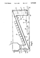
- FIG. 1 shows a longitudinal section of a first exemplary embodiment of an apparatus for treating medical hazardous wastes
- FIGS. 2a and 2b each show a half cross section of a microwave chamber of the apparatus according to FIG. 1,
- FIG. 3 shows a block diagram of functional units of the apparatus according to FIG. 1,
- FIG. 4 shows a longitudinal section of another embodiment of the loading and comminution region
- FIG. 5 shows a longitudinal section of a second exemplary embodiment of an apparatus for treating medical hazardous wastes
- FIG. 6 shows a longitudinal section of a third exemplary embodiment of an apparatus for treating medical hazardous wastes
- FIG. 7 shows a longitudinal section of a mobile embodiment of an apparatus for treating medical hazardous wastes.
- FIG. 1 shows a first exemplary embodiment of an apparatus for treating medical hazardous wastes in a container 1 which integrates a loading section, a treatment section and an unloading section to form a compact waste disposal plant.
- the loading section first comprises a loading chamber 3 which is constructed as a funnel and can be sealed in a fluid-tight manner by means of a cover 4.
- the cover 4 is opened and closed by means of hydraulic cylinders 5 by means of which the cover 4 is mounted on the roof of the container 1.
- a pushing device Disposed inside the loading chamber 3 is a pushing device which is constructed as a rotating blade 6 and which precomminutes the refuse load 2 and feeds it to a refuse comminutor 7.
- the rotating blade 6 is driven by a geared motor.
- One or more suction slots 8 of a suction system 9 are disposed in the side walls 10 of the loading chamber 3 and form a suction screen which sucks off any atmospheric germs drawn up by opening the cover 4.
- the suction slots 8 remain in operation in order to prevent any escape of germs from the loading chamber 3.
- the suction system 9 comprises a roughing filter and a high-performance suspended-material filter.
- the funnel with cover 4 and suction system 9 provide the loading chamber 3 with the function of a waste sluice.
- An injection connection 11 with associated valve is furthermore let into the side wall 10 in order that superheated steam can be introduced into the waste disposal plant for the purpose of decontamination during stoppage, at shift end and also for repair and maintenance operations.
- the latter can furthermore be superficially heated using a back-up heating system.
- the side walls 10 are heated to a temperature of over 100° C., preferably to temperatures between 105° C. and 140° C.
- the articles of waste 2 can be loaded manually, or automatically by means of a lift-and-tip device 12 which picks up waste containers 13 and empties them into the loading chamber 3.
- the lift-and-tip device 12 may be disposed at the rearside of the container 1 and moves one or more refuse containers 13 in the direction of the arrow for the particular loading operation.
- the waste containers 13 are preferably 120 l to 1100 l containers.
- a hydraulic system 14 is provided for actuating the lift-and-tip device 12.
- a weighing device may be integrated into the lift-and-tip device 12 to determine the weight per waste container 13 and possibly record it electronically.
- the refuse comminutor 7 which also forms part of the loading section, comprises a cutting mechanism having two contrary-running knife driving shafts 15 into which cutting bodies and drivers are inserted.
- the cutting bodies are so designed that a granulation of the waste material fed with the aid of the rotating blade 6 is achieved.
- the refuse is mixed at the same time.
- a controllable electric motor is provided for driving the refuse comminutor 7.
- the treatment section comprises a microwave chamber 16 and a temperature maintenance chamber 17.
- the connection between the loading section and the treatment section is provided by a transfer funnel 18 which is detachably connected to the outlet of the refuse comminutor 7 and the inlet of the microwave chamber 16.
- the transfer funnel 18 is preferably flanged on.
- a spraying head 19 which is connected to a water tank 20 fitted with a pump, but may also be connected to an external water main.
- the spraying device is used to spray in water in a controlled manner to achieve uniform moistening of the granulated material produced by the refuse comminutor 7 for the subsequent treatment.
- the water paths are preferably shut off and opened up by solenoid-operated valves.
- the spraying time and rest time may be varied by means of a timer as a function of the degree of moistness of the refuse load.
- the transfer funnel 18 is exploited as intermediate storage for the granulated material since the comminutor 7 generally provides more granulated material than the microwave chamber 16 can handle.
- a filling level sensor 21 for a minimum and maximum filling level is disposed in the region of the inlet and outlet to monitor the degree of filling of the transfer funnel 18.
- the electric motor of the refuse comminutor 7 is preferably controlled in a manner such that the filling level of the transfer funnel 18 always varies between the minimum and maximum filling level.
- the comminution operation can consequently be regulated by means of the filling level sensors 21.
- the transfer funnel may also incorporate a further injection connection 11 for introducing the superheated steam for decontaminating the emptied waste disposal plant.
- a steam generator 22 is fitted to supply these injection connections 11.
- the microwave chamber 16 is used to heat the comminuted and moist, possibly moistened, refuse in a continuous process with a selectable conveying speed and layer thickness of the comminuted refuse.
- the microwave chamber 16 comprises a duct-like trough 23 in which a conveying device 24 is disposed. Along the through housing 23, there is disposed a central microwave source with a waveguide system or a plurality of microwave sources 25 are disposed closely adjacent to each other. To couple in the microwave radiation, the trough 23 has inlet openings 26 or is composed of material transparent to microwaves in these regions.
- the microwave sources 25 may be disposed at a plurality of sides of the through housing 23.
- the granulated material travelling through is heated up by internal heating and evaporated moisture.
- the through housing 23 and the microwave sources 25 attached thereto form a sealed treatment chamber.
- conveying device 24 use may be made, for example, of a conveying screw, a conveying belt or a conveying ram.
- the conveying device 24 removes the comminuted refuse from the transfer funnel 18 and conveys it at an adjustable speed to the outlet 27 of the microwave chamber 16.
- the mixing of the conveyed granulated material may be improved by installing the microwave chamber 16 with an incline to achieve uniform irradiation and a good heat exchange. Since the microwave chamber is always only partially, preferably 2/3, filled, the granulated refuse material consequently always partially falls back again.
- the angle of inclination is preferably between 10° and 50°.
- FIGS. 2a and 2b show the construction of the microwave chamber 16 in detail.
- the trough 23 is constructed as a U-shaped trough and the conveying device 24 comprises an open shaftless conveying helix which rotates in the U-shaped trough.
- the trough and conveying helix are composed of metal, preferably stainless steel, and additional wearing bars 28 of a softer material are provided on which the conveying helix runs.
- the trough 23 is closed in a fluid-tight manner by means of a trough cover 29 on which the microwave sources 25 are mounted. In the region of the microwave sources 25, the covering function of the trough cover 29 may also be taken over by the microwave sources 25 with guide system connected, as is further explained below.
- the trough dimensions depend on the required layer thickness in the microwave chamber 16, and the throughput quantity and throughput speed. Owing to the absence of a shaft, the conveying helix has a large free cross section which minimizes the risk of clogging and plug formation.
- the conveying helix furthermore acts as a three-dimensional field distributor for the microwaves coupled in, as a result of which the material to be treated is more satisfactorily reached by the microwave radiation.
- the conveying helix is driven by a motor 30 whose rotary speed can be controlled.
- the heating in the microwave chamber 16 is achieved by two different heat injections while the material is passing through.
- a first heat injection is carried out by the microwave sources 25, 12 of which are disposed next to each other in this case but their number may, however, be between 1 and 20 depending on power level.
- the microwave energy produced by the individual microwave sources 25 is in each case coupled in via a waveguide 31 and deflectors 32, which form a resonance chamber 33, into the treatment chamber 34 of the microwave chamber 16.
- the deflectors 32 are attached to the trough 23 by means of detachable attachment devices 35.
- the resonance chambers 33 are disposed next to each other.
- the treatment chamber 34 is covered at the top by means of sheets 36 of a material which is transparent to microwaves such as, for example, polytetrafluoroethylene (PTFE).
- PTFE polytetrafluoroethylene
- the switch-on time of the microwave sources 25 can be controlled.
- the electrical power may be supplied via a plug connection 37 (see FIG. 1).
- the switch-on times are selected in a manner such that the microwaves heat the granulated material to or above a selectable minimum temperature in order that the required thermal treatment, for example a disinfection, can be carried out.
- the conveying speed and filling levels are automatically adjusted.
- a second heat injection is used to back up the heating produced by the microwaves.
- the trough 23 is surrounded by a heating device.
- the heating device comprises electrical heating coils 40 which are preferably disposed immediately next to the wall of the trough 23.
- the heating device comprises a double-walled partial jacket 38 for a heat transfer medium such as, for example, thermal oil or superheated steam, which partial jacket is also preferably disposed immediately next to the wall of the trough 23.
- a thermal insulation 39 which is screened on the outside by a covering 41, is adjacently installed in both designs.
- This second heat injection may comprise different heating circuits in order that a controlled continuous quantity of heat can be fed to the individual regions of the microwave chamber 16.
- the temperature reached by the granulated material is determined in the region of the inlet 43 of the temperature maintenance chamber 17 by means of a measuring sensor 42.
- the minimum temperature is above 95° C. and is preferably 98° C. to 102° C.
- the outlet 27 of the microwave chamber 16 is connected to the inlet 43 of the temperature maintanance chamber 17.
- the temperature maintenance chamber 17 comprises a duct-like through housing 44 in which the temperature treatment of the granulated material takes place in a continuous process.
- the heated granulated material supplied by the conveying device 24 of the microwave chamber 16 is taken over by means of a conveying device 45 and passed through the temperature maintenance chamber 17 during a selectable minimum residence time. During this time, the granulated material is held at at least the minimum temperature.
- the trough 44 is encased on the outside by a heating device 46 which is constructed, for example, as in the case of the microwave chamber 16.
- the heat introduced by the heating device 46 prevents the granulated material cooling down, with the result that the temperature produced in the microwave chamber 16 can be maintained.
- a temperature level may optionally be adjusted between inlet 43 and outlet 48 of the temperature maintenance chamber 17, in which case the inlet and outlet temperature must have at least a minimum temperature necessary for the treatment operation.
- the inlet temperature is measured and documented by means of the measuring sensor 42 and the outlet temperature of the granulated material in the temperature maintenance chamber 17 by means of a measuring sensor 47.
- the conveying device 45 comprises a conveying screw which, like the one in the microwave chamber 16, is of shaftless construction.
- the conveying screw 45 is driven by a motor 49 with controllable rotary speed. Its rotary speed is matched to the conveying helix 24 in a manner such that a certain compacting of the granulated material, which is initially loose for heating by microwaves, is brought about in the temperature maintenance chamber 17, as a result of which the heat conduction is improved in this treatment phase and the heat losses are reduced.
- Metals preferably stainless steel, are envisaged as the material for the through 44 and the conveying device 45. However, plastics or ceramic materials may also be used.
- an adjoining unloading section may comprise only an ejection opening or, as shown in FIG. 1, it may have an unloading screw 50, driven by a motor 51, which can be swung laterally out of the container 1.
- the container 1 shown in FIG. 1 can be a stationary installation or, according to FIG. 1, be disposed on a motor vehicle trailer 52 for mobile use.
- a space heating system 53 ensures an adequate ambient temperature.
- the waste disposal plant may be operated manually, or semiautomatically or fully automatically. All the essential controlled variables and monitoring functions are incorporated in a process-control computer 54.
- the center piece of the process-control computer 54 is a stored-program control system which contains an operating program for switch and sensor scanning, motor and source control, and monitoring and driving the indicators.
- the function units connected to the process-control computer 54 are shown in a block circuit diagram of FIG. 3 for the loading and comminution region, the heating region and the temperature maintenance region with unloading system.
- the controlled variables of the function units which affect each other are denoted by connecting lines with arrows. This measure ensures that the variables, critical for a thermal treatment, in particular a disinfection, of minimum temperature and maintenance duration are maintained and deviations are automatically corrected.
- the trough heating systems and the funnel heating systems are first switched on. Once the specified set temperature is reached, water and air pressure are available and the cover of the loading sluice is closed, the plant can be switched to automatic operation observing the safety requirements and loaded.
- the lift-and-tip device 12 which also controls the opening of the cover 4, ejects wastes from the containers 13 to be emptied into the opened funnel 3.
- the suction system 8 is switched off.
- the rotating blade 6 and the comminutor 7 are then set in operation.
- the rotating blade 6 shreds the articles of waste and feeds them in a controlled manner to the comminutor 7 which provides for granulation and mixing.
- the granulated material then drops into the transfer funnel 18 with automatic filling level monitoring and controlled moistening.
- the filling level monitoring regulates the comminution operation by switching off the comminutor 17 if the transfer funnel 18 is filled and stopping the further process sequence if the transfer funnel 18 is empty.
- the thermal disinfection is now initiated.
- the granulated material is heated in the microwave chamber at a microwave frequency of 2,450 MHz approved here for industrial purposes.
- the granulated material is passed at a defined conveying speed through the microwave chamber 16 where a rapid direct production of heat is brought about in the material as a function of the dielectric properties. This effect is increased further by the water added which evaporates under the action of the microwaves.
- This application of vapor is maintained in the microwave chamber 16 since at the outlet side a natural seal is built up by the granulated material transferred to the temperature maintenance chamber 17.
- the granulated material temperature reached is subject to monitoring. If it drops below a minimum temperature, the conveying speed is reduced until the minimum temperature is reached again. In this process, the rotary speed of the conveying helix 24 is adjusted to the mean throughout level (kg/h) and the minimum temperature to be reached.
- the final structural group for the disinfection is the temperature maintenance chamber 17 with its maintenance zone.
- the granulated material is held at the minimum temperature, achieved by means of microwaves, of over 95° C. to eliminate the pathogenic germs.
- the minimum residence time depends on the number of germs, the germ type and the filling quantity.
- the maintenance time can be adjusted in a controlled manner by means of the speed of the conveying screw 45.
- the minimum temperature is demonstrated by documenting the automatically measured inlet and outlet temperature. Temperature losses are compensated for by the backup heating. If the transfer funnel 18 is empty, the microwaves sources 25 and, with a certain lag, the conveying devices 24, 45 are first switched off automatically. The treated granulated material is ejected for removal. After the completion of work, the plant is steam-disinfected.
- a process according to the invention for continuously heat-treating particulate articles comprises the following two steps.
- a first step the comminuted or already partly particulate articles are loosened up after carrying out moistening with an aqueous medium and passed through a microwave field while mixing the entire cross section of the conveyed layer thickness, and heated in this process to a minimum temperature with internal heating.
- the articles so heated are at least slightly compacted and held at at least the minimum temperature during a minimum residence time. To maintain this minimum temperature with heat losses occurring, the articles can be heated indirectly during this holding phase so that any drop below the minimum temperature is avoided.
- the articles may be held, for example, at the minimum temperature until they are dried. If the use of disinfectants is additionally required for a treatment operation, spray injection of the same is possible during the first and/or second step.
- FIG. 4 shows another embodiment of the loading and comminution region, in particular the loading chamber 3, which is constructed as a three-chamber sluice.
- the loading chamber has an essentially cylindrical hollow body 55 which is provided at the bottom with a funnel-type discharge section 56. Disposed centrally in the hollow body 55 is a sluice wheel 57 with three sluice paddles 58 each extending outwards at an angle of 120° in each case.
- the sluice paddles subdivide the hollow body 55 into three chambers which are separated from each other and which rotate anticlockwise in the direction of the arrow when the sluice wheel 57 turns.
- the sluice chambers pass through in sequence a filling station 59, a transfer station 60 and a disinfection station 61.
- wastes 2 can be loaded into the chamber situated in the filling station after the cover 4 has been opened. Turning through 120° rotates this chamber with the wastes 2 received into the transfer station 60, where the rotating blade 6 operates and a transfer to the comminutor 7 takes place.
- the emptied chamber is then brought to the disinfection station 61 which is equipped with at least one spraying head 62 for introducing a disinfection mist and which can be extracted with a suction system 9 according to FIG. 1.
- the first chamber, freed of germs, is then transferred again to the filling station.
- the chambers roasted through 120° and 240° with respect to this chamber pass through said stations 59, 60, 61 with a displacement in time, as a result of which continuous loading with wastes 2 is possible.
- the region of the loading chamber opened for a loading is consequently always germ-free.
- FIG. 5 shows a second exemplary embodiment of the apparatus for treating medical wastes.
- the temperature maintenance chamber 17 is in this case constructed as a compact large-volume container 63.
- This container 63 is installed essentially vertically so that after the plant has been put into operation, the granulated material heated up in the microwave chamber 16 drops down under the action of gravity into the container 63 and fills the latter.
- the container 63 is sealed at the bottom with a removable cover 64.
- the granulated material loaded into the container 63 remains in the latter for a minimum residence time at at least the minimum temperature.
- the required thermal treatment e.g.
- the minimum temperature and minimum residence time can be correspondingly adjusted and checked by means of the temperature measuring sensors 42, 47.
- the cover 64 is removed after a first filling of the container 63.
- the granulated material transferred from the conveying device of the microwave chamber 16 to the temperature maintenance chamber causes the granulated material already loaded into the container 63 to travel through.
- the dimensions of the container 63 can be matched to the throughput quantity of the plant.
- the cross section of the unloading device 50 connected to the bottom of the container 63 is of smaller construction than the cross section of the conveying duct of the microwave chamber 16 so that more granulated material is constantly transferred from the microwave chamber 16 to the container 63 than can be delivered by the latter via the unloading device 50, as a result of which a compacting of the granulated material in the container 63 is achieved.
- the second heat injection for the microwave chamber 16 and an indirect heating of the granulated material in the container 63 is carried out in the case of the plant according to FIG. 5 by means of a heat transfer medium.
- the microwave chamber 16 and the container 63 have chambered walls with a double jacket 65 through which the heat transfer medium, for example thermal oil, superheated steam, is pumped from a reservoir 68.
- the double jackets 65 of the microwave chamber 16 and of the container 63 are connected to each other to form a circuit for the heat transfer medium via pipelines 69 in which a pump 71 and at least one valve 72 are fitted for supply and control.
- the heating device of the loading chamber 3 can also be fed from this heat transfer circuit.
- the preheating of the granulated material thus achieved in the transfer funnel 18 is checked by means of temperature sensors 67.
- the plant can be constructed as described in relation to FIGS. 1 to 4 and may also be equipped with an electrical heating system.
- FIG. 6 shows a third exemplary embodiment of an apparatus for treating medical hazardous wastes in which the heat produced in the microwave irradiation of the moistened waste can be at least partially recovered.
- a circulating air pipeline 73 which can be shut off and which is led into the loading chamber 3 is connected in the region of the outlet 27 of the microwave chamber 16. Hot air can be sucked out of the housing duct 23 of the microwave chamber 16 by means of a pump 74 inserted in the circulating air pipeline 73 and fed to the funnel-type loading chamber 3.
- this plant does not differ from that described in FIG. 1.
- FIG. 7 shows a mobile embodiment of an apparatus for treating medical wastes.
- this plant comprises a loading section with loading chamber 3, comminutor 7 and transfer funnel 18, a treatment section with microwave chamber 16 and also a temperature maintenance chamber and an unloading section, said operating units being accommodated in a container 1 which forms the superstructure of a motor vehicle 75.
- the temperature maintenance chamber and the unloading section have been omitted.
- the plant is furthermore equipped with a heating device, described in relation to FIG. 5, by means of circulation of heat transfer oil.
- heat transfer oil is envisaged as heat transfer medium.
- Pipelines 69 with pump 71 inserted and valve 72 connect the reservoir 68 to the double-walled jackets 65 of the housing duct 23 of the microwave chamber 16 and of the loading chamber 3.
- a radiator 76 of the space heating system 53 (see FIG. 1) is fed via pipelines 70.
- An exhaust gas heat exchanger 77 which is disposed around the exhaust 78 of the motor vehicle 75 is provided to heat up the heat transfer oil stored in the reservoir 68.
- the reservoir 68 is connected to the exhaust gas heat exchanger 77 via pipelines 79 to heat up the heat transfer medium.
- an expansion vessel 80, a safety valve 81 and a pressure gauge 82 are connected to the reservoir 68.
- the heat produced in the internal combustion engine of the motor vehicle can thus be employed for the thermal treatment operation on the medical hazardous refuse in a manner such that the plant is heated up during the drive to the points of use without additional energy costs and preheating times and dwell times of the plant are minimized.
Abstract
Description
Claims (18)
Priority Applications (1)
| Application Number | Priority Date | Filing Date | Title |
|---|---|---|---|
| US07/768,870 US5270000A (en) | 1989-04-19 | 1990-04-16 | Apparatus and process for treating medical hazardous wastes |
Applications Claiming Priority (2)
| Application Number | Priority Date | Filing Date | Title |
|---|---|---|---|
| DE3912751A DE3912751C1 (en) | 1989-04-19 | 1989-04-19 | |
| US07/768,870 US5270000A (en) | 1989-04-19 | 1990-04-16 | Apparatus and process for treating medical hazardous wastes |
Publications (1)
| Publication Number | Publication Date |
|---|---|
| US5270000A true US5270000A (en) | 1993-12-14 |
Family
ID=25880056
Family Applications (1)
| Application Number | Title | Priority Date | Filing Date |
|---|---|---|---|
| US07/768,870 Expired - Lifetime US5270000A (en) | 1989-04-19 | 1990-04-16 | Apparatus and process for treating medical hazardous wastes |
Country Status (1)
| Country | Link |
|---|---|
| US (1) | US5270000A (en) |
Cited By (53)
| Publication number | Priority date | Publication date | Assignee | Title |
|---|---|---|---|---|
| WO1997026019A1 (en) * | 1996-01-16 | 1997-07-24 | Devine Thomas J | Mobile apparatus and process for treating infectious waste |
| US5792421A (en) * | 1995-07-24 | 1998-08-11 | Microsterile Safe Corporation | Non-intrusive microwave decontamination of infectious waste |
| US5951947A (en) * | 1998-03-13 | 1999-09-14 | A Creative Research And Testing Co | Vacuumized microwave decontamination of waste materials |
| US5968400A (en) * | 1996-08-14 | 1999-10-19 | Westinghouse Savannah River Company | Tandem microwave waste remediation and decontamination system |
| US5972291A (en) * | 1997-01-30 | 1999-10-26 | Thermal Waste Technologies, Inc. | Method and apparatus for disposal of infectious and medical waste |
| US6262405B1 (en) | 1997-08-14 | 2001-07-17 | Westinghouse Savannah River Company | Medical waste treatment and decontamination system |
| WO2002014764A2 (en) * | 2000-08-16 | 2002-02-21 | Novak John F | Method and apparatus for microwave utilization |
| US6446887B1 (en) | 2000-04-24 | 2002-09-10 | Aegis Bio-Systems, L.L.C. | Portable medical waste plant |
| US6534754B2 (en) | 1997-08-14 | 2003-03-18 | Westinghouse Savannah River Company, L.L.C. | Microwave off-gas treatment apparatus and process |
| US6595208B1 (en) * | 1997-08-08 | 2003-07-22 | Battelle Memorial Institute | Dispensing device |
| US20040005242A1 (en) * | 2000-10-27 | 2004-01-08 | Pavel Koulik | Method and device for sterilising a liquid |
| US20050163687A1 (en) * | 2002-02-05 | 2005-07-28 | Econos S.R.L. | Device for the sterilization of hospital waste |
| US6926863B1 (en) * | 1998-07-23 | 2005-08-09 | Helmut Goeldner | Method and device for treating contaminated materials |
| US20050228694A1 (en) * | 2004-04-12 | 2005-10-13 | Sanitec Industries, Inc., A California Corporation | Processing of documents with medical and other waste |
| US20050228682A1 (en) * | 2004-04-12 | 2005-10-13 | Sanitec Industries, Inc., A California Corporation | Method and system for tracking medical and other waste |
| WO2005103884A1 (en) * | 2004-04-12 | 2005-11-03 | Sanitec Industries, Inc. | Processing of documents with medical and other waste |
| US20060045797A1 (en) * | 2004-08-27 | 2006-03-02 | Don Frazier | System for treating bio-hazardous medical waste |
| US7080650B1 (en) | 2001-04-26 | 2006-07-25 | Jwc Environmental | Screenings washer |
| US7086405B1 (en) * | 2001-04-26 | 2006-08-08 | Jwc Environmental | Screenings washer |
| US20070014995A1 (en) * | 2005-07-12 | 2007-01-18 | Jacob Chacko | Thin rotary-fiberized glass insulation and process for producing same |
| US7383842B1 (en) | 2006-08-03 | 2008-06-10 | Jwc Environmental | Screenings washer apparatus |
| US20090123339A1 (en) * | 2007-11-14 | 2009-05-14 | Sampson Donald L | Bio-Waste Sterilizer |
| US20100129257A1 (en) * | 2008-11-25 | 2010-05-27 | Estech, Llc | Waste treatment vessel featuring tilt mechanism and associated door arrangement |
| US20100278688A1 (en) * | 2008-11-24 | 2010-11-04 | Damien Tanaka | Containerized Medical Waste Treatment System and Related Method |
| WO2010144741A1 (en) | 2009-06-12 | 2010-12-16 | Ashwin-Ushas Corporation, Inc. | Microwave remediation of medical wastes |
| KR101017517B1 (en) | 2008-12-29 | 2011-02-28 | 엔 하이테크 주식회사 | High-speed shredding apparatus for livestock sterilization |
| ITTV20090204A1 (en) * | 2009-10-20 | 2011-04-21 | Smc Technology Srl | MODULAR POLYVALENT EQUIPMENT WITH CROSS-CUP MODULES FOR DRYING AND FAST AND CONTINUOUS DRYING AND DEHUMIDIFICATION OF BULK AND MATERIAL MATERIAL AND DRYING PROCEDURE, DEHUMIDIFICATION OF BULK MATERIAL |
| US20110099894A1 (en) * | 2009-11-01 | 2011-05-05 | Sharps Compliance, Inc. | Method and system of making a burnable fuel |
| US20110155020A1 (en) * | 2009-12-29 | 2011-06-30 | Sharps Compliance, Inc. | System and method for making cement and cement derived therefrom |
| US20110165035A1 (en) * | 2006-05-10 | 2011-07-07 | Lewis Robert W | Waste treatment apparatus and method |
| US8163045B2 (en) | 2009-12-29 | 2012-04-24 | Sharps Compliance, Inc | Method and system of making a burnable fuel |
| US20130091722A1 (en) * | 2010-07-23 | 2013-04-18 | Kwok Fai Lam | Microwave Dryer and Microwave Drying Method |
| WO2013110900A1 (en) * | 2012-01-27 | 2013-08-01 | Bertin Technologies | Automaton and method for processing waste |
| US20130240513A1 (en) * | 2012-03-14 | 2013-09-19 | Microwave Materials Technologies, Inc. | Enhanced control of a microwave heating system |
| US9393545B1 (en) * | 2015-02-17 | 2016-07-19 | Chun Il Koh | Apparatus for treating food waste |
| IT201700017156A1 (en) * | 2017-02-16 | 2018-08-16 | Medical S P A | Apparatus for separating organic liquids from solid envelopes containing them |
| US20190071194A1 (en) * | 2017-09-07 | 2019-03-07 | M. Tanner Ag | Transport and feed unit for preforms |
| US10399086B2 (en) | 2015-02-09 | 2019-09-03 | Viradys Medical Waste Solutions, LLC | System and method for disinfecting medical waste |
| US11085016B1 (en) | 2020-01-20 | 2021-08-10 | Chio Kang Medical, Inc. | Method for screening bacteria capable of degrading ethylene oxide |
| US11103608B1 (en) | 2020-07-03 | 2021-08-31 | Chio Kang Medical, Inc. | Mobile pretreatment apparatus and an operating method thereof, and a mobile analysis apparatus and an operating method thereof |
| US11103829B1 (en) | 2020-03-18 | 2021-08-31 | Chio Kang Medical, Inc. | Systems and methods for treating ethylene oxide waste gas |
| US11110390B1 (en) | 2020-03-18 | 2021-09-07 | Chio Kang Medical, Inc. | Systems and methods for treating sterilization exhaust gas containing ethylene oxide |
| US11124438B2 (en) | 2020-01-20 | 2021-09-21 | Chio Kang Medical, Inc. | Alcaligenes faecalis for degrading ethylene oxide |
| US11123449B1 (en) * | 2020-07-03 | 2021-09-21 | Chio Kang Medical, Inc. | Mobile sterilization system, mobile execution system, and mobile analysis system |
| US11123680B1 (en) | 2020-03-18 | 2021-09-21 | Chio Kang Medical, Inc. | Devices, systems, and methods for treating ethylene oxide waste gas |
| US11125498B1 (en) | 2020-03-18 | 2021-09-21 | Chio Kang Medical, Inc. | Gas liquefaction separator, gas liquefaction recovery system, and method for separating and recovering ethylene oxide |
| US11129914B1 (en) | 2020-03-19 | 2021-09-28 | Chio Kang Medical, Inc. | Ethylene oxide adsorption tower and recovery system, and method for recovering ethylene oxide |
| US11130095B1 (en) | 2020-03-18 | 2021-09-28 | Chio Kang Medical, Inc. | Sterilization exhaust gas treating system and method for treating ethylene oxide-containing sterilization exhaust gas by using the same |
| US11130939B2 (en) | 2020-01-20 | 2021-09-28 | Chio Kang Medical, Inc. | Bacteria for degrading ethylene oxide and uses thereof |
| US11136253B1 (en) | 2020-03-18 | 2021-10-05 | Chio Kang Medical, Inc. | Microbiological treatment system for ethylene oxide exhaust gas |
| US11220667B2 (en) | 2020-01-20 | 2022-01-11 | Chio Kang Medical, Inc. | Bacteria for degrading ethylene oxide and applications thereof |
| WO2022245348A1 (en) * | 2021-05-19 | 2022-11-24 | A.L.M Holding Company | Microwave waste heating system and related features |
| KR102642818B1 (en) * | 2022-12-23 | 2024-03-05 | 엠엔테크(주) | Mobile medical waste sterilization treatment system |
Citations (12)
| Publication number | Priority date | Publication date | Assignee | Title |
|---|---|---|---|---|
| US1594894A (en) * | 1924-11-10 | 1926-08-03 | Int Motor Co | Ventilating and heating means for inclosed vehicles |
| US3295982A (en) * | 1962-07-23 | 1967-01-03 | Fmc Corp | Continuous rendering method and apparatus |
| US3664706A (en) * | 1970-06-03 | 1972-05-23 | Euclid | Exhaust diverting valve for dumpable vehicles having heated dump bodies |
| US3831288A (en) * | 1970-11-24 | 1974-08-27 | Furnace L Dev Ltd | Drying and sterilising apparatus |
| US3853480A (en) * | 1971-01-21 | 1974-12-10 | Kaelin J R | Apparatus for the conversion of prepared refuse sewage sludge mixtures into earth substance by biological decomposition |
| US4351644A (en) * | 1980-03-27 | 1982-09-28 | Degussa Aktiengesellschaft | Process for handling liquid cyanuric chloride |
| US4371503A (en) * | 1979-06-17 | 1983-02-01 | Dietmar Aichelmann | Apparatus for the vaporization of aluminum trichloride |
| US4546226A (en) * | 1982-04-29 | 1985-10-08 | Entron Technologies, Inc. | Method and apparatus for the conveying and radio frequency processing of dielectric materials |
| US4551057A (en) * | 1982-03-16 | 1985-11-05 | Zoller-Kipper Gmbh | Device for emptying containers into a collector |
| US4608261A (en) * | 1983-11-04 | 1986-08-26 | New Zealand Government Property Corporation | Method and apparatus for producing a puffed foodstuff |
| US4832700A (en) * | 1982-01-09 | 1989-05-23 | Sandoz Ltd. | Process and apparatus for preparing dust-free granular material |
| US4999471A (en) * | 1988-06-03 | 1991-03-12 | Barilla G.E.R. F.Lli - Societa Per Azioni | Method for heat prepackaged food products using microwaves in a heated superatmospheric chamber |
-
1990
- 1990-04-16 US US07/768,870 patent/US5270000A/en not_active Expired - Lifetime
Patent Citations (12)
| Publication number | Priority date | Publication date | Assignee | Title |
|---|---|---|---|---|
| US1594894A (en) * | 1924-11-10 | 1926-08-03 | Int Motor Co | Ventilating and heating means for inclosed vehicles |
| US3295982A (en) * | 1962-07-23 | 1967-01-03 | Fmc Corp | Continuous rendering method and apparatus |
| US3664706A (en) * | 1970-06-03 | 1972-05-23 | Euclid | Exhaust diverting valve for dumpable vehicles having heated dump bodies |
| US3831288A (en) * | 1970-11-24 | 1974-08-27 | Furnace L Dev Ltd | Drying and sterilising apparatus |
| US3853480A (en) * | 1971-01-21 | 1974-12-10 | Kaelin J R | Apparatus for the conversion of prepared refuse sewage sludge mixtures into earth substance by biological decomposition |
| US4371503A (en) * | 1979-06-17 | 1983-02-01 | Dietmar Aichelmann | Apparatus for the vaporization of aluminum trichloride |
| US4351644A (en) * | 1980-03-27 | 1982-09-28 | Degussa Aktiengesellschaft | Process for handling liquid cyanuric chloride |
| US4832700A (en) * | 1982-01-09 | 1989-05-23 | Sandoz Ltd. | Process and apparatus for preparing dust-free granular material |
| US4551057A (en) * | 1982-03-16 | 1985-11-05 | Zoller-Kipper Gmbh | Device for emptying containers into a collector |
| US4546226A (en) * | 1982-04-29 | 1985-10-08 | Entron Technologies, Inc. | Method and apparatus for the conveying and radio frequency processing of dielectric materials |
| US4608261A (en) * | 1983-11-04 | 1986-08-26 | New Zealand Government Property Corporation | Method and apparatus for producing a puffed foodstuff |
| US4999471A (en) * | 1988-06-03 | 1991-03-12 | Barilla G.E.R. F.Lli - Societa Per Azioni | Method for heat prepackaged food products using microwaves in a heated superatmospheric chamber |
Cited By (79)
| Publication number | Priority date | Publication date | Assignee | Title |
|---|---|---|---|---|
| US5792421A (en) * | 1995-07-24 | 1998-08-11 | Microsterile Safe Corporation | Non-intrusive microwave decontamination of infectious waste |
| WO1997026019A1 (en) * | 1996-01-16 | 1997-07-24 | Devine Thomas J | Mobile apparatus and process for treating infectious waste |
| US5968400A (en) * | 1996-08-14 | 1999-10-19 | Westinghouse Savannah River Company | Tandem microwave waste remediation and decontamination system |
| US5972291A (en) * | 1997-01-30 | 1999-10-26 | Thermal Waste Technologies, Inc. | Method and apparatus for disposal of infectious and medical waste |
| US6595208B1 (en) * | 1997-08-08 | 2003-07-22 | Battelle Memorial Institute | Dispensing device |
| US6534754B2 (en) | 1997-08-14 | 2003-03-18 | Westinghouse Savannah River Company, L.L.C. | Microwave off-gas treatment apparatus and process |
| US6262405B1 (en) | 1997-08-14 | 2001-07-17 | Westinghouse Savannah River Company | Medical waste treatment and decontamination system |
| US5951947A (en) * | 1998-03-13 | 1999-09-14 | A Creative Research And Testing Co | Vacuumized microwave decontamination of waste materials |
| US6926863B1 (en) * | 1998-07-23 | 2005-08-09 | Helmut Goeldner | Method and device for treating contaminated materials |
| US6446887B1 (en) | 2000-04-24 | 2002-09-10 | Aegis Bio-Systems, L.L.C. | Portable medical waste plant |
| US6726136B2 (en) | 2000-04-24 | 2004-04-27 | Aegis Bio Systems, L.L.C. | Waste treatment plant |
| WO2002014764A2 (en) * | 2000-08-16 | 2002-02-21 | Novak John F | Method and apparatus for microwave utilization |
| WO2002014764A3 (en) * | 2000-08-16 | 2002-03-28 | John F Novak | Method and apparatus for microwave utilization |
| US6618957B2 (en) | 2000-08-16 | 2003-09-16 | John F. Novak | Method and apparatus for microwave utilization |
| US20040005242A1 (en) * | 2000-10-27 | 2004-01-08 | Pavel Koulik | Method and device for sterilising a liquid |
| US7080650B1 (en) | 2001-04-26 | 2006-07-25 | Jwc Environmental | Screenings washer |
| US7086405B1 (en) * | 2001-04-26 | 2006-08-08 | Jwc Environmental | Screenings washer |
| US20050163687A1 (en) * | 2002-02-05 | 2005-07-28 | Econos S.R.L. | Device for the sterilization of hospital waste |
| US20090004051A1 (en) * | 2004-04-12 | 2009-01-01 | Sanitec Industries, Inc. | Processing of Documents with Medical and Other Waste |
| US20050228682A1 (en) * | 2004-04-12 | 2005-10-13 | Sanitec Industries, Inc., A California Corporation | Method and system for tracking medical and other waste |
| WO2005103989A2 (en) * | 2004-04-12 | 2005-11-03 | Sanitec Industries, Inc. | Processing of documents with medical and other waste |
| WO2005103884A1 (en) * | 2004-04-12 | 2005-11-03 | Sanitec Industries, Inc. | Processing of documents with medical and other waste |
| US20050228694A1 (en) * | 2004-04-12 | 2005-10-13 | Sanitec Industries, Inc., A California Corporation | Processing of documents with medical and other waste |
| WO2005103989A3 (en) * | 2004-04-12 | 2007-01-18 | Sanitec Ind Inc | Processing of documents with medical and other waste |
| US20060045797A1 (en) * | 2004-08-27 | 2006-03-02 | Don Frazier | System for treating bio-hazardous medical waste |
| WO2006025938A2 (en) * | 2004-08-27 | 2006-03-09 | Don Frazier | System for treating bio-hazardous medical waste |
| WO2006025938A3 (en) * | 2004-08-27 | 2006-10-26 | Don Frazier | System for treating bio-hazardous medical waste |
| US20070014995A1 (en) * | 2005-07-12 | 2007-01-18 | Jacob Chacko | Thin rotary-fiberized glass insulation and process for producing same |
| US20110165035A1 (en) * | 2006-05-10 | 2011-07-07 | Lewis Robert W | Waste treatment apparatus and method |
| US8318104B2 (en) * | 2006-05-10 | 2012-11-27 | Lewis Robert W | Waste treatment apparatus and method |
| US7383842B1 (en) | 2006-08-03 | 2008-06-10 | Jwc Environmental | Screenings washer apparatus |
| WO2009064538A2 (en) * | 2007-11-14 | 2009-05-22 | Donald Sampson | Bio-waste sterilizer |
| US20120328484A1 (en) * | 2007-11-14 | 2012-12-27 | Globe-Tek Llc | Biowaste sterilizer |
| US8282892B2 (en) * | 2007-11-14 | 2012-10-09 | Globe-Tek Llc | Bio-Waste sterilizer |
| US20090123339A1 (en) * | 2007-11-14 | 2009-05-14 | Sampson Donald L | Bio-Waste Sterilizer |
| US8404191B2 (en) * | 2007-11-14 | 2013-03-26 | Globe-Tek Llc | Biowaste sterilizer |
| WO2009064538A3 (en) * | 2007-11-14 | 2009-07-16 | Donald Sampson | Bio-waste sterilizer |
| US20100278688A1 (en) * | 2008-11-24 | 2010-11-04 | Damien Tanaka | Containerized Medical Waste Treatment System and Related Method |
| US20100129257A1 (en) * | 2008-11-25 | 2010-05-27 | Estech, Llc | Waste treatment vessel featuring tilt mechanism and associated door arrangement |
| WO2010065076A1 (en) * | 2008-11-25 | 2010-06-10 | Estech, Llc | Waste treatment vessel featuring tilt mechanism and associated door arrangement |
| KR101017517B1 (en) | 2008-12-29 | 2011-02-28 | 엔 하이테크 주식회사 | High-speed shredding apparatus for livestock sterilization |
| US20100316526A1 (en) * | 2009-06-12 | 2010-12-16 | Ashwin-Ushas Corporation, Inc. | Microwave remediation of medical wastes |
| US8518324B2 (en) | 2009-06-12 | 2013-08-27 | Ashwin-Ushas Corporation, Inc. | Microwave remediation of medical wastes |
| WO2010144741A1 (en) | 2009-06-12 | 2010-12-16 | Ashwin-Ushas Corporation, Inc. | Microwave remediation of medical wastes |
| US8318086B2 (en) | 2009-06-12 | 2012-11-27 | Ashwin-Ushas Corporation, Inc. | Microwave remediation of medical wastes |
| ITTV20090204A1 (en) * | 2009-10-20 | 2011-04-21 | Smc Technology Srl | MODULAR POLYVALENT EQUIPMENT WITH CROSS-CUP MODULES FOR DRYING AND FAST AND CONTINUOUS DRYING AND DEHUMIDIFICATION OF BULK AND MATERIAL MATERIAL AND DRYING PROCEDURE, DEHUMIDIFICATION OF BULK MATERIAL |
| EP2315496A1 (en) * | 2009-10-20 | 2011-04-27 | Smc Technology S.R.L. | Apparatus for continuous drying of bulk materials |
| US8100989B2 (en) | 2009-11-01 | 2012-01-24 | Kunik Burton J | Method and system of making a burnable fuel |
| US20110099894A1 (en) * | 2009-11-01 | 2011-05-05 | Sharps Compliance, Inc. | Method and system of making a burnable fuel |
| US8163045B2 (en) | 2009-12-29 | 2012-04-24 | Sharps Compliance, Inc | Method and system of making a burnable fuel |
| US20110155020A1 (en) * | 2009-12-29 | 2011-06-30 | Sharps Compliance, Inc. | System and method for making cement and cement derived therefrom |
| US8268073B2 (en) | 2009-12-29 | 2012-09-18 | Sharps Compliance, Inc. | System and method for making cement and cement derived therefrom |
| US20130091722A1 (en) * | 2010-07-23 | 2013-04-18 | Kwok Fai Lam | Microwave Dryer and Microwave Drying Method |
| US9435585B2 (en) * | 2010-07-23 | 2016-09-06 | Kwok Fai Lam | Microwave dryer and microwave drying method |
| WO2013110900A1 (en) * | 2012-01-27 | 2013-08-01 | Bertin Technologies | Automaton and method for processing waste |
| FR2986167A1 (en) * | 2012-01-27 | 2013-08-02 | Bertin Technologies Sa | AUTOMATE AND PROCESS FOR TREATING WASTE |
| US9980325B2 (en) * | 2012-03-14 | 2018-05-22 | Microwave Materials Technologies, Inc. | Enhanced control of a microwave heating system |
| US20130240513A1 (en) * | 2012-03-14 | 2013-09-19 | Microwave Materials Technologies, Inc. | Enhanced control of a microwave heating system |
| US10399086B2 (en) | 2015-02-09 | 2019-09-03 | Viradys Medical Waste Solutions, LLC | System and method for disinfecting medical waste |
| US9393545B1 (en) * | 2015-02-17 | 2016-07-19 | Chun Il Koh | Apparatus for treating food waste |
| IT201700017156A1 (en) * | 2017-02-16 | 2018-08-16 | Medical S P A | Apparatus for separating organic liquids from solid envelopes containing them |
| US20190071194A1 (en) * | 2017-09-07 | 2019-03-07 | M. Tanner Ag | Transport and feed unit for preforms |
| CN109466907A (en) * | 2017-09-07 | 2019-03-15 | M.坦纳股份公司 | The transmission of parison and feed unit |
| US10669050B2 (en) * | 2017-09-07 | 2020-06-02 | M. Tanner Ag | Transport and feed unit for preforms |
| US11130939B2 (en) | 2020-01-20 | 2021-09-28 | Chio Kang Medical, Inc. | Bacteria for degrading ethylene oxide and uses thereof |
| US11085016B1 (en) | 2020-01-20 | 2021-08-10 | Chio Kang Medical, Inc. | Method for screening bacteria capable of degrading ethylene oxide |
| US11220667B2 (en) | 2020-01-20 | 2022-01-11 | Chio Kang Medical, Inc. | Bacteria for degrading ethylene oxide and applications thereof |
| US11124438B2 (en) | 2020-01-20 | 2021-09-21 | Chio Kang Medical, Inc. | Alcaligenes faecalis for degrading ethylene oxide |
| US11110390B1 (en) | 2020-03-18 | 2021-09-07 | Chio Kang Medical, Inc. | Systems and methods for treating sterilization exhaust gas containing ethylene oxide |
| US11123680B1 (en) | 2020-03-18 | 2021-09-21 | Chio Kang Medical, Inc. | Devices, systems, and methods for treating ethylene oxide waste gas |
| US11125498B1 (en) | 2020-03-18 | 2021-09-21 | Chio Kang Medical, Inc. | Gas liquefaction separator, gas liquefaction recovery system, and method for separating and recovering ethylene oxide |
| US11130095B1 (en) | 2020-03-18 | 2021-09-28 | Chio Kang Medical, Inc. | Sterilization exhaust gas treating system and method for treating ethylene oxide-containing sterilization exhaust gas by using the same |
| US11136253B1 (en) | 2020-03-18 | 2021-10-05 | Chio Kang Medical, Inc. | Microbiological treatment system for ethylene oxide exhaust gas |
| US11103829B1 (en) | 2020-03-18 | 2021-08-31 | Chio Kang Medical, Inc. | Systems and methods for treating ethylene oxide waste gas |
| US11129914B1 (en) | 2020-03-19 | 2021-09-28 | Chio Kang Medical, Inc. | Ethylene oxide adsorption tower and recovery system, and method for recovering ethylene oxide |
| US11123449B1 (en) * | 2020-07-03 | 2021-09-21 | Chio Kang Medical, Inc. | Mobile sterilization system, mobile execution system, and mobile analysis system |
| US11103608B1 (en) | 2020-07-03 | 2021-08-31 | Chio Kang Medical, Inc. | Mobile pretreatment apparatus and an operating method thereof, and a mobile analysis apparatus and an operating method thereof |
| WO2022245348A1 (en) * | 2021-05-19 | 2022-11-24 | A.L.M Holding Company | Microwave waste heating system and related features |
| KR102642818B1 (en) * | 2022-12-23 | 2024-03-05 | 엠엔테크(주) | Mobile medical waste sterilization treatment system |
Similar Documents
| Publication | Publication Date | Title |
|---|---|---|
| US5270000A (en) | Apparatus and process for treating medical hazardous wastes | |
| CA2051445C (en) | Apparatus and process for treating medical hazardous wastes | |
| EP0931553B1 (en) | Waste treatment apparatus and method | |
| CA2842752C (en) | Pressurized screw system using air locks for waste disposal | |
| US6752956B1 (en) | Waste treatment control system | |
| US6446887B1 (en) | Portable medical waste plant | |
| US7144550B2 (en) | Mobile apparatus and process for treating infectious waste | |
| US5720438A (en) | Mobile apparatus and process for treating infectious waste | |
| US20070197852A1 (en) | Method and apparatus for treatment and disposal of waste material | |
| WO1991016084A1 (en) | Process and unit for disinfection and sterilisation of infectious waste | |
| KR20010009772A (en) | A process of organic waste articles used vermiculture | |
| CA1316324C (en) | Infectious waste decontamination | |
| MXPA97007401A (en) | System and process for dealing with desire material |
Legal Events
| Date | Code | Title | Description |
|---|---|---|---|
| AS | Assignment |
Owner name: ABB ENVIRONMENTAL SERVICES INC. A CORPORATION OF Free format text: ASSIGNMENT OF ASSIGNORS INTEREST.;ASSIGNORS:GOLDNER, HELMUT;KAMANN, REINHOLD;LEINSKI, HEINZ;REEL/FRAME:005930/0547 Effective date: 19901028 |
|
| AS | Assignment |
Owner name: ABB SANITEC, INC. A CORP. OF DE, NEW JERSEY Free format text: ASSIGNMENT OF ASSIGNORS INTEREST;ASSIGNOR:ABB ENVIRONMENTAL SERVICES INC.;REEL/FRAME:006706/0834 Effective date: 19930916 |
|
| STCF | Information on status: patent grant |
Free format text: PATENTED CASE |
|
| AS | Assignment |
Owner name: SANITEC, INC., NEW JERSEY Free format text: CERTIFICATE OF CORPORATE NAME CHANGE;ASSIGNOR:ABB SANITEC, INC.;REEL/FRAME:007570/0963 Effective date: 19950511 |
|
| FEPP | Fee payment procedure |
Free format text: PAT HOLDER CLAIMS SMALL ENTITY STATUS - SMALL BUSINESS (ORIGINAL EVENT CODE: SM02); ENTITY STATUS OF PATENT OWNER: SMALL ENTITY Free format text: PAYOR NUMBER ASSIGNED (ORIGINAL EVENT CODE: ASPN); ENTITY STATUS OF PATENT OWNER: SMALL ENTITY |
|
| FPAY | Fee payment |
Year of fee payment: 4 |
|
| REMI | Maintenance fee reminder mailed | ||
| FPAY | Fee payment |
Year of fee payment: 8 |
|
| SULP | Surcharge for late payment |
Year of fee payment: 7 |
|
| AS | Assignment |
Owner name: SANITEC, LTD, NEW JERSEY Free format text: CERTIFIATE OF CORPORATE NAME CHANGE;ASSIGNOR:SANITEC, INC.;REEL/FRAME:012822/0660 Effective date: 20010413 |
|
| AS | Assignment |
Owner name: SANITEC GROUP, LLC, NEW JERSEY Free format text: ASSIGNMENT OF ASSIGNORS INTEREST;ASSIGNOR:SANITEC, LTD;REEL/FRAME:012822/0897 Effective date: 20020222 |
|
| FEPP | Fee payment procedure |
Free format text: PAYER NUMBER DE-ASSIGNED (ORIGINAL EVENT CODE: RMPN); ENTITY STATUS OF PATENT OWNER: SMALL ENTITY Free format text: PAYOR NUMBER ASSIGNED (ORIGINAL EVENT CODE: ASPN); ENTITY STATUS OF PATENT OWNER: SMALL ENTITY |
|
| AS | Assignment |
Owner name: PLATINUM FUNDING CORP., NEW JERSEY Free format text: SECURITY AGREEMENT;ASSIGNOR:SANITEC GROUP, LLC;REEL/FRAME:014734/0420 Effective date: 20020301 Owner name: PLATINUM FUNDING CORP., NEW JERSEY Free format text: SECURITY INTEREST;ASSIGNOR:SANITEC, LTD.;REEL/FRAME:014725/0777 Effective date: 20010605 Owner name: SANITEC INDUSTRIES, INC., DISTRICT OF COLUMBIA Free format text: ASSIGNMENT OF FACTORING AGREEMENTS AND SECURITY AGREEMENTS;ASSIGNOR:PLATINUM FUNDING CORP.;REEL/FRAME:014725/0754 Effective date: 20031124 |
|
| AS | Assignment |
Owner name: SANITEC INDUSTRIES, INC., CALIFORNIA Free format text: ASSIGNMENT OF ASSIGNORS INTEREST;ASSIGNOR:SANITEC GROUP, LLC;REEL/FRAME:014990/0213 Effective date: 20040217 |
|
| AS | Assignment |
Owner name: SANITEC INDUSTRIES, INC., CALIFORNIA Free format text: FORECLOSURE DEFAULT JUDGEMENT (2P) AND COMPLAINT (9P);ASSIGNOR:SANITEC GROUP, LLC, A DELAWARE LIMITED LIABILITY COMPANY;REEL/FRAME:015232/0034 Effective date: 20040305 |
|
| AS | Assignment |
Owner name: SANITEC INDUSRTIES, INC., CALIFORNIA Free format text: FORECLOSURE DEFAULT JUDGMENT (2 P) AND COMPLAIN (9 P);ASSIGNOR:GUARDIAN INVESTMENTS, LLC;REEL/FRAME:015232/0499 Effective date: 20040305 Owner name: SANITEC INDUSTRIES, INC., CALIFORNIA Free format text: FORECLOSURE CONSENT JUDGMENT (5P) AND COMPLAINT (9P);ASSIGNOR:DELLOIACOVO, JOSEPH;REEL/FRAME:015232/0526 Effective date: 20040204 Owner name: SANITEC INDUSTRIES, INC., CALIFORNIA Free format text: JUDGMENT;ASSIGNOR:DANSON, WAYNE I.;REEL/FRAME:015232/0511 Effective date: 20040302 |
|
| FPAY | Fee payment |
Year of fee payment: 12 |
|
| AS | Assignment |
Owner name: SANITEC INDUSTRIES, INC., DISTRICT OF COLUMBIA Free format text: ASSIGNMENT OF ASSIGNORS INTEREST;ASSIGNOR:SANITEC, LTD.;REEL/FRAME:017251/0868 Effective date: 20050712 |
|
| AS | Assignment |
Owner name: MICRO-WASTE CORPORATION, TEXAS Free format text: FINAL JUDGMENT, U.S. SOUTHERN DISTRICT COURT;ASSIGNOR:SANITEC INDUSTRIES, INC.;REEL/FRAME:019102/0524 Effective date: 20070301 |
|
| AS | Assignment |
Owner name: MICRO-WASTE CORPORATION,TEXAS Free format text: CORRECTIVE ASSIGNMENT TO CORRECT THE NATURE OF CONVEYANCE PREVIOUSLY RECORDED ON REEL 019102 FRAME 0524. ASSIGNOR(S) HEREBY CONFIRMS THE ORDER ON ATTORNEYS' FEES AND FINAL JUDGMENT REGARDING PATENT VALIDITY AND LICENSE;ASSIGNOR:SANITEC INDUSTRIES, INC.;REEL/FRAME:024434/0619 Effective date: 20070301 |