US5275844A - Process for forming a crack-free boron nitride coating on a carbon structure - Google Patents
Process for forming a crack-free boron nitride coating on a carbon structure Download PDFInfo
- Publication number
- US5275844A US5275844A US07/819,647 US81964792A US5275844A US 5275844 A US5275844 A US 5275844A US 81964792 A US81964792 A US 81964792A US 5275844 A US5275844 A US 5275844A
- Authority
- US
- United States
- Prior art keywords
- carbon
- coating
- boron nitride
- thermal expansion
- temperature
- Prior art date
- Legal status (The legal status is an assumption and is not a legal conclusion. Google has not performed a legal analysis and makes no representation as to the accuracy of the status listed.)
- Expired - Fee Related
Links
Images

Classifications
-
- C—CHEMISTRY; METALLURGY
- C23—COATING METALLIC MATERIAL; COATING MATERIAL WITH METALLIC MATERIAL; CHEMICAL SURFACE TREATMENT; DIFFUSION TREATMENT OF METALLIC MATERIAL; COATING BY VACUUM EVAPORATION, BY SPUTTERING, BY ION IMPLANTATION OR BY CHEMICAL VAPOUR DEPOSITION, IN GENERAL; INHIBITING CORROSION OF METALLIC MATERIAL OR INCRUSTATION IN GENERAL
- C23C—COATING METALLIC MATERIAL; COATING MATERIAL WITH METALLIC MATERIAL; SURFACE TREATMENT OF METALLIC MATERIAL BY DIFFUSION INTO THE SURFACE, BY CHEMICAL CONVERSION OR SUBSTITUTION; COATING BY VACUUM EVAPORATION, BY SPUTTERING, BY ION IMPLANTATION OR BY CHEMICAL VAPOUR DEPOSITION, IN GENERAL
- C23C16/00—Chemical coating by decomposition of gaseous compounds, without leaving reaction products of surface material in the coating, i.e. chemical vapour deposition [CVD] processes
- C23C16/22—Chemical coating by decomposition of gaseous compounds, without leaving reaction products of surface material in the coating, i.e. chemical vapour deposition [CVD] processes characterised by the deposition of inorganic material, other than metallic material
- C23C16/30—Deposition of compounds, mixtures or solid solutions, e.g. borides, carbides, nitrides
- C23C16/34—Nitrides
- C23C16/342—Boron nitride
-
- C—CHEMISTRY; METALLURGY
- C23—COATING METALLIC MATERIAL; COATING MATERIAL WITH METALLIC MATERIAL; CHEMICAL SURFACE TREATMENT; DIFFUSION TREATMENT OF METALLIC MATERIAL; COATING BY VACUUM EVAPORATION, BY SPUTTERING, BY ION IMPLANTATION OR BY CHEMICAL VAPOUR DEPOSITION, IN GENERAL; INHIBITING CORROSION OF METALLIC MATERIAL OR INCRUSTATION IN GENERAL
- C23C—COATING METALLIC MATERIAL; COATING MATERIAL WITH METALLIC MATERIAL; SURFACE TREATMENT OF METALLIC MATERIAL BY DIFFUSION INTO THE SURFACE, BY CHEMICAL CONVERSION OR SUBSTITUTION; COATING BY VACUUM EVAPORATION, BY SPUTTERING, BY ION IMPLANTATION OR BY CHEMICAL VAPOUR DEPOSITION, IN GENERAL
- C23C16/00—Chemical coating by decomposition of gaseous compounds, without leaving reaction products of surface material in the coating, i.e. chemical vapour deposition [CVD] processes
- C23C16/56—After-treatment
Definitions
- the present invention specifically relates to an improved process for forming a coating of boron nitride on a carbon-carbon composite to provide oxidation protection at high temperature and to the article formed by the process.
- Carbon-carbon composites are important materials for aerospace applications because they retain high strength and toughness at high temperature.
- the use of carbon-carbon composite material is presently limited because of its susceptibility to oxidation.
- Oxidation protection may be provided by depositing a protective layer on the surface of the carbon-carbon composite which is resistant to oxidation.
- a preferred material is boron nitride.
- the method of the present invention produces a "crack-free" pyrolytic boron nitride coating over a carbon-carbon composite structure to provide oxidation protection for the composite structure at temperatures of up to 800° C. and higher.
- "crack-free” means a coating essentially free of cross-plane cracks which would allow air to penetrate to the carbon-carbon composite.
- the presence of cracks parallel to the deposition surface are not as serious provided they are not accompanied by such cross-plane cracks. Accordingly, as long as there are essentially no cracks which penetrate in a direction transverse to the deposition surface, the coating is considered “crack-free".
- the process of the present invention for producing a crack-free coating of pyrolytic boron nitride on a carbon-carbon composite structure comprises contacting said carbon-carbon composite structure with vapors of ammonia and gaseous boron halide in a controlled atmosphere containing such vapors and maintaining such atmosphere within a temperature range of between 1500° C. and 1700° C.
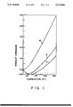
- FIG. 1 is a graph comparing the thermal expansion curve of a boron nitride coating deposited on a carbon-carbon composite in accordance with the present invention with both the thermal expansion curve of a commercial pyrolytic boron nitride (PBN) coating and the carbon-carbon substrate upon which the boron nitride coating composite was formed; and
- PBN pyrolytic boron nitride
- FIG. 2 shows the thermal expansion curve for a boron nitride coating deposited in accordance with a modified version of the process of the present invention for rendering the coating impervious to water.
- a conventional carbon-carbon composite is a material composed of a woven or non-woven fabric of carbon fibers with a carbonaceous material directly bonded to the carbon fibers to form a unitary structure.
- An example of a carbon-carbon composite is a woven fabric of carbon fibers obtained by carbonizing polyacrylonitrile (PAN) fibers, forming a shaped substrate from the carbon fibers and depositing a pyrolytic material such as pyrolytic carbon on the carbon fibers.
- PAN polyacrylonitrile
- the deposition of carbon is typically carried out by introducing a hydrocarbon gas into a furnace containing the carbon fiber substrate under conditions permitting the gas to decompose and carbonize at the surface of the carbon fibers.
- the reactor temperature may be between 1450° C. and 2300° C. with a preferential temperature range of between 1850° C. and 2200° C.
- the method, as described in the aforementioned patent, is conventionally practiced at a deposition temperature of between 1850° C.-1950° C.
- a pyrolytic boron nitride coating may be formed on a carbon-carbon composite structure with a low thermal expansion of between 0.14 to 0.32 percent over a temperature range between room temperature and 1500° C. thereby closely conforming to the typical thermal expansion of a carbon-carbon composite.
- a conventional vacuum furnace may be used as taught and described in U.S. Pat. No. 3,152,006.
- the process of the present invention requires the deposition temperature to lie in a critical range of between 1500° C.-1700° C. and preferably at about 1650° C.
- the pyrolytic boron nitride coating which is stress-free at deposition temperature, is subjected to less than 0.1% tensile strain when cooled to room temperature. Because the thermal expansion of the coating nearly matches that of the carbon-carbon composite, good coating-to-substrate adherence is obtained. Furthermore, no special surface preparation is needed for good coating adherence.
- the pyrolytic boron nitride coating is formed in accordance with the present invention by mounting the carbon-carbon substrate to be coated in a hot wall deposition chamber, preferably of graphite, which can be electrically heated by resistance or induction inside a vacuum vessel.
- the carbon-carbon substrate(s) may be fixedly supported or rotationally supported in the deposition chamber.
- the deposition furnace is evacuated and the deposition chamber is heated to a uniform temperature of between 1500°-1650° C. When the desired temperature is reached, boron trichloride and ammonia, with or without nitrogen dilution, are metered into the deposition chamber to start the growth of pyrolytic boron nitride (PBN).
- PBN pyrolytic boron nitride
- All of the PBN coatings formed in accordance with the present invention have a hexagonal crystal structure and a density in the range of 1.75-1.90 g/cc.
- the coated composites from this first run were turned upside down and mounted again in the deposition chamber for a second coating to seal the small areas that were in contact with the graphite support in the first run.
- the second coating was carried out at 1650° C. and 400 microns Hg for 285 minutes.
- the PBN coatings from these two runs were found to be more translucent than coatings made at higher temperatures, and most of the coatings were free of visual cracks. It was determined that the average density of these PBN coatings was about 1.8 g/cc, and the percent expansion parallel to the deposition plane was 0.32% up to 1500° C. Although this expansion is still about 0.15% higher than that of the lowest CTE carbon-carbon composites, other properties of the PBN, such as its lower modulus (and the smaller temperature difference from coating temperature to room temperature compared with coatings made at higher temperatures) are important for yielding crack-free coatings.
- This example is a scale-up of the conditions of Example 1, using a 17-inch diameter by 27-inch long deposition chamber to coat in a single run three pairs of carbon-carbon composite plates each about 12 ⁇ 29 cm ⁇ 2-3 mm. These plates were coated at 1650° C. for 900 minutes, using a pressure of 300 microns and an NH 3 :BCl 3 ratio of 3.6. The approximate coating thickness was in the range 17-21 mils. The scale-up was successful in that 11 of the 12 coated surfaces were crack-free. The thermal expansion curve for one of the coatings is illustrated as curve B in FIG. 1. The thermal expansion of the PBN coating may have been affected by the thermal expansion of the composite being coated.
- the composite had a thermal expansion of 0.12% to 1500° C., and the PBN coating on this composite expanded 0.2% to 1500° C.
- Another composite not shown in FIG. 1 expanded about 0.16% on heating to 1500° C., and the PBN coating on it expanded 0.28% to 1500° C. In both cases, the PBN coatings would have a residual strain of about 0.1% at room temperature.
- the as-deposited boron nitride coating can be rendered resistant to water without otherwise adversely affecting coating performance by the additional step of annealing the coatings at temperatures above 1750° C. to 2000° C. and preferably between about 1800° C. to 1900° C. to minimize dimensional changes caused by annealing.
- This additional step eliminates the susceptibility to water reaction.
- the following examples substantiate the resistance of the coating to moisture attack:
- Two carbon-carbon composite bars each about 75 ⁇ 25 ⁇ 2-3 mm, were mounted using a small hole near one end and a horizontal support rod, and then these bars were PBN coated using the pilot plant size CVD reactor of Examples 1 and 2.
- the samples were coated for 270 minutes at 1650° C. and 500 microns Hg, using an NH 3 :BCl 3 molar ratio of 3.8, and then the coating was continued while the furnace was heated to 1900° C. in ten minutes and held at 1900° C. for another 25 minutes.
- the outer coating was more typical of high-temperature PBN deposits, the bulk of the deposit from Run 8904 was similar in structure to that of an unannealed 1650° C. deposit.
- the FWHM 002 was 67°, and the interlayer spacing c o /2 was 3.42 ⁇ , which is typical of turbostratic PBN deposits.
- the FWHM 002 is the full width at half-maximum intensity of the x-ray(002) orientation distribution and is a measure of the preferred orientation of the crystallites in the PBN deposit as defined e.g. in A. W. Moore et al, Journal of Applied Physics, Vol. 65, p. 5109, 1989.
- a thermal expansion of 0.14-0.27% at 1500° C. was measured for this crack-free coating depending on substrate and location. More importantly, this heat-treated coating, unlike an unannealed 1650° C. PBN coating, was resistant to reaction with water at 95°-100° C.
- the density measured ranged from 1.83-1.96 g/cc, and the percent expansion to 1500° C. was 0.20%, a very satisfactory value for compatibility with the low CTE carbon-carbon composites.
- Curve E is illustrative of the low CTE carbon-carbon composite thermal expansion.
- FIG. 2 confirms that there is no adverse effect on the thermal expansion from the additional annealing step.
Landscapes
- Chemical & Material Sciences (AREA)
- General Chemical & Material Sciences (AREA)
- Chemical Kinetics & Catalysis (AREA)
- Engineering & Computer Science (AREA)
- Materials Engineering (AREA)
- Mechanical Engineering (AREA)
- Metallurgy (AREA)
- Organic Chemistry (AREA)
- Inorganic Chemistry (AREA)
- Chemical Vapour Deposition (AREA)
- Ceramic Products (AREA)
Abstract
Description
NH.sub.3 +BCl.sub.3 → BN+3HCl
Claims (5)
Priority Applications (1)
| Application Number | Priority Date | Filing Date | Title |
|---|---|---|---|
| US07/819,647 US5275844A (en) | 1990-08-08 | 1992-01-10 | Process for forming a crack-free boron nitride coating on a carbon structure |
Applications Claiming Priority (3)
| Application Number | Priority Date | Filing Date | Title |
|---|---|---|---|
| US56410890A | 1990-08-08 | 1990-08-08 | |
| WOUS-91/05505 | 1991-08-08 | ||
| US07/819,647 US5275844A (en) | 1990-08-08 | 1992-01-10 | Process for forming a crack-free boron nitride coating on a carbon structure |
Related Parent Applications (1)
| Application Number | Title | Priority Date | Filing Date |
|---|---|---|---|
| US56410890A Continuation-In-Part | 1990-08-08 | 1990-08-08 |
Publications (1)
| Publication Number | Publication Date |
|---|---|
| US5275844A true US5275844A (en) | 1994-01-04 |
Family
ID=24253181
Family Applications (1)
| Application Number | Title | Priority Date | Filing Date |
|---|---|---|---|
| US07/819,647 Expired - Fee Related US5275844A (en) | 1990-08-08 | 1992-01-10 | Process for forming a crack-free boron nitride coating on a carbon structure |
Country Status (5)
| Country | Link |
|---|---|
| US (1) | US5275844A (en) |
| EP (1) | EP0495095B1 (en) |
| JP (1) | JP2729289B2 (en) |
| CA (1) | CA2067145C (en) |
| DE (1) | DE69116847T2 (en) |
Cited By (8)
| Publication number | Priority date | Publication date | Assignee | Title |
|---|---|---|---|---|
| US5593728A (en) * | 1994-11-01 | 1997-01-14 | Advanced Ceramics Corporation | Interface coating for ceramic fibers |
| US5693581A (en) * | 1995-10-03 | 1997-12-02 | Advanced Ceramics Corporation | Method of manufacturing a pyrolytic boron nitride compact |
| US5718416A (en) * | 1996-01-30 | 1998-02-17 | Pyrotek, Inc. | Lid and containment vessel for refining molten metal |
| US20030175575A1 (en) * | 2002-02-28 | 2003-09-18 | Omg Ag & Co. Kg | PEM fuel cell stack and method of making same |
| US20090081478A1 (en) * | 2007-09-21 | 2009-03-26 | Siemens Power Generation, Inc. | Crack-Free Erosion Resistant Coatings on Steels |
| US20090169781A1 (en) * | 2007-12-31 | 2009-07-02 | Marc Schaepkens | Low thermal conductivity low density pyrolytic boron nitride material, method of making, and articles made therefrom |
| US20150141235A1 (en) * | 2012-12-28 | 2015-05-21 | United Technologies Corporation | Carbon fiber-reinforced article and method therefor |
| CN113109131A (en) * | 2021-04-02 | 2021-07-13 | 武汉飞盛建设工程有限公司 | Waterproof coating prevents effect tester that ftractures |
Families Citing this family (3)
| Publication number | Priority date | Publication date | Assignee | Title |
|---|---|---|---|---|
| JP5854512B2 (en) * | 2012-12-17 | 2016-02-09 | 信越化学工業株式会社 | Method for producing pyrolytic boron nitride-coated carbonaceous substrate |
| JP6198334B2 (en) | 2014-06-05 | 2017-09-20 | 信越化学工業株式会社 | Carbon heater |
| JP2016102232A (en) * | 2014-11-27 | 2016-06-02 | 信越化学工業株式会社 | Pyrolytic boron nitride coated substrate and production method thereof |
Citations (6)
| Publication number | Priority date | Publication date | Assignee | Title |
|---|---|---|---|---|
| US3152006A (en) * | 1961-06-29 | 1964-10-06 | High Temperature Materials Inc | Boron nitride coating and a process of producing the same |
| US3578403A (en) * | 1968-07-05 | 1971-05-11 | Union Carbide Corp | Recrystallization of pyrolytic boron nitride |
| US4225569A (en) * | 1977-06-14 | 1980-09-30 | Kanebo Ltd. | Carbon-carbon composite material and method for its production |
| US4522842A (en) * | 1982-09-09 | 1985-06-11 | At&T Bell Laboratories | Boron nitride X-ray masks with controlled stress |
| US4849146A (en) * | 1985-02-28 | 1989-07-18 | Denki Kagaku Kogyo Kabushiki Kaisha | Method for producing pyrolytic boron nitride article |
| US4900526A (en) * | 1985-03-04 | 1990-02-13 | Research Development Corporation Of Japan | Polycrystalline rhombohedral boron nitride and method of producing the same |
Family Cites Families (1)
| Publication number | Priority date | Publication date | Assignee | Title |
|---|---|---|---|---|
| JPH01252780A (en) * | 1988-03-31 | 1989-10-09 | Sumitomo Metal Mining Co Ltd | Boron nitride coated body and production thereof |
-
1991
- 1991-08-08 EP EP91918125A patent/EP0495095B1/en not_active Expired - Lifetime
- 1991-08-08 DE DE69116847T patent/DE69116847T2/en not_active Expired - Fee Related
- 1991-08-08 CA CA002067145A patent/CA2067145C/en not_active Expired - Fee Related
- 1991-08-08 JP JP3516606A patent/JP2729289B2/en not_active Expired - Fee Related
-
1992
- 1992-01-10 US US07/819,647 patent/US5275844A/en not_active Expired - Fee Related
Patent Citations (6)
| Publication number | Priority date | Publication date | Assignee | Title |
|---|---|---|---|---|
| US3152006A (en) * | 1961-06-29 | 1964-10-06 | High Temperature Materials Inc | Boron nitride coating and a process of producing the same |
| US3578403A (en) * | 1968-07-05 | 1971-05-11 | Union Carbide Corp | Recrystallization of pyrolytic boron nitride |
| US4225569A (en) * | 1977-06-14 | 1980-09-30 | Kanebo Ltd. | Carbon-carbon composite material and method for its production |
| US4522842A (en) * | 1982-09-09 | 1985-06-11 | At&T Bell Laboratories | Boron nitride X-ray masks with controlled stress |
| US4849146A (en) * | 1985-02-28 | 1989-07-18 | Denki Kagaku Kogyo Kabushiki Kaisha | Method for producing pyrolytic boron nitride article |
| US4900526A (en) * | 1985-03-04 | 1990-02-13 | Research Development Corporation Of Japan | Polycrystalline rhombohedral boron nitride and method of producing the same |
Cited By (11)
| Publication number | Priority date | Publication date | Assignee | Title |
|---|---|---|---|---|
| US5593728A (en) * | 1994-11-01 | 1997-01-14 | Advanced Ceramics Corporation | Interface coating for ceramic fibers |
| US5693581A (en) * | 1995-10-03 | 1997-12-02 | Advanced Ceramics Corporation | Method of manufacturing a pyrolytic boron nitride compact |
| US5718416A (en) * | 1996-01-30 | 1998-02-17 | Pyrotek, Inc. | Lid and containment vessel for refining molten metal |
| US20030175575A1 (en) * | 2002-02-28 | 2003-09-18 | Omg Ag & Co. Kg | PEM fuel cell stack and method of making same |
| US20090081478A1 (en) * | 2007-09-21 | 2009-03-26 | Siemens Power Generation, Inc. | Crack-Free Erosion Resistant Coatings on Steels |
| US7758925B2 (en) | 2007-09-21 | 2010-07-20 | Siemens Energy, Inc. | Crack-free erosion resistant coatings on steels |
| US20090169781A1 (en) * | 2007-12-31 | 2009-07-02 | Marc Schaepkens | Low thermal conductivity low density pyrolytic boron nitride material, method of making, and articles made therefrom |
| WO2009088471A1 (en) * | 2007-12-31 | 2009-07-16 | Momentive Performance Materials Inc. | Low thermal conductivity low density pyrolytic boron nitride material, method of making, and articles made therefrom |
| US20150141235A1 (en) * | 2012-12-28 | 2015-05-21 | United Technologies Corporation | Carbon fiber-reinforced article and method therefor |
| US9446989B2 (en) * | 2012-12-28 | 2016-09-20 | United Technologies Corporation | Carbon fiber-reinforced article and method therefor |
| CN113109131A (en) * | 2021-04-02 | 2021-07-13 | 武汉飞盛建设工程有限公司 | Waterproof coating prevents effect tester that ftractures |
Also Published As
| Publication number | Publication date |
|---|---|
| DE69116847T2 (en) | 1996-07-04 |
| CA2067145A1 (en) | 1992-02-09 |
| WO1992002662A1 (en) | 1992-02-20 |
| CA2067145C (en) | 1999-02-16 |
| EP0495095B1 (en) | 1996-01-31 |
| DE69116847D1 (en) | 1996-03-14 |
| JP2729289B2 (en) | 1998-03-18 |
| EP0495095A1 (en) | 1992-07-22 |
| WO1992002662A3 (en) | 2004-04-29 |
| JPH05502914A (en) | 1993-05-20 |
Similar Documents
| Publication | Publication Date | Title |
|---|---|---|
| EP0149044B1 (en) | Boron nitride containing titanium nitride, method of producing the same and composite ceramics produced therefrom | |
| US5275844A (en) | Process for forming a crack-free boron nitride coating on a carbon structure | |
| US6737120B1 (en) | Oxidation-protective coatings for carbon-carbon components | |
| EP0529594A1 (en) | A glassy carbon coated graphite component for use in the production of silicon crystal growth | |
| US5593728A (en) | Interface coating for ceramic fibers | |
| US4900526A (en) | Polycrystalline rhombohedral boron nitride and method of producing the same | |
| RU2059025C1 (en) | Boron nitride crucible manufacture method | |
| JPH07508703A (en) | Monolithic ceramic/fiber reinforced ceramic composites | |
| EP0529593B1 (en) | A glass carbon coated graphite chuck for use in producing polycrystalline silicon | |
| JP4514846B2 (en) | High purity carbon fiber reinforced carbon composite material and method for producing the same | |
| Moore et al. | Improved interface coatings for SiC fibers in ceramic composites | |
| He et al. | Microstructural evolution of Hi-NicalonTM SiC fibers annealed and crept in various oxygen partial pressure atmospheres | |
| Azema et al. | Oxidation stages of aluminium nitride thin films obtained by plasma-enhanced chemical vapour deposition (PECVD) | |
| US5114749A (en) | Method for manufacturing carbon material having good resistance to oxidation by coating the carbon material with an inorganic polysilazane and then heating | |
| JP3218092B2 (en) | Method for producing oxidation resistant C / C composite | |
| US5972511A (en) | Process for forming low thermal expansion pyrolytic nitride coatings on low thermal expansion materials and coated article | |
| JP2733788B2 (en) | Manufacturing method of carbon fiber coated with carbide ceramics | |
| WO1992002662A2 (en) | Process for forming crack-free pyrolytic boron nitride on a carbon structure and article | |
| Chappell et al. | The fabrication of ceramic-coated carbon fibre duplex elements | |
| JP4358313B2 (en) | Seed chuck for semiconductor single crystal pulling equipment | |
| JPH09507465A (en) | Method for densifying porous structure with boron nitride and porous structure densified with boron nitride | |
| JP3844273B2 (en) | Oxidation resistant C / C composite and method for producing the same | |
| JPS5824394B2 (en) | Titsukahousofukugoutaino Seizouhouhou | |
| Devlin et al. | Chemical vapor infiltration with microwave heating | |
| JPH0648867A (en) | Production of boron carbide-coated carbon material |
Legal Events
| Date | Code | Title | Description |
|---|---|---|---|
| AS | Assignment |
Owner name: UNION CARBIDE COATINGS SERVICE TECHNOLOGY CORPORAT Free format text: ASSIGNMENT OF ASSIGNORS INTEREST.;ASSIGNOR:MOORE, ARTHUR W.;REEL/FRAME:006096/0976 Effective date: 19920423 |
|
| AS | Assignment |
Owner name: PRAXAIR S.T. TECHNOLOGY, INC., COLORADO Free format text: CHANGE OF NAME;ASSIGNOR:UNION CARBIDE COATINGS SERVICE TECHNOLOGY CORPORATION;REEL/FRAME:006334/0986 Effective date: 19920611 |
|
| AS | Assignment |
Owner name: ADVANCED CERAMICS CORPORATION, OHIO Free format text: ASSIGNMENT OF ASSIGNORS INTEREST;ASSIGNOR:BRAXAIR S. T. TECHNOLOGY, INC.;REEL/FRAME:006548/0893 Effective date: 19930302 |
|
| AS | Assignment |
Owner name: SOCIETY NATIONAL BANK, OHIO Free format text: SECURITY INTEREST;ASSIGNOR:ADVANCED CERAMICS CORPORATION;REEL/FRAME:006569/0360 Effective date: 19930302 |
|
| FEPP | Fee payment procedure |
Free format text: PAT HOLDER CLAIMS SMALL ENTITY STATUS - SMALL BUSINESS (ORIGINAL EVENT CODE: SM02); ENTITY STATUS OF PATENT OWNER: LARGE ENTITY |
|
| FEPP | Fee payment procedure |
Free format text: PAYOR NUMBER ASSIGNED (ORIGINAL EVENT CODE: ASPN); ENTITY STATUS OF PATENT OWNER: LARGE ENTITY |
|
| FEPP | Fee payment procedure |
Free format text: PAT HLDR NO LONGER CLAIMS SMALL ENT STAT AS SMALL BUSINESS (ORIGINAL EVENT CODE: LSM2); ENTITY STATUS OF PATENT OWNER: LARGE ENTITY |
|
| FPAY | Fee payment |
Year of fee payment: 4 |
|
| SULP | Surcharge for late payment | ||
| AS | Assignment |
Owner name: KEYBANK NATIONAL ASSOCIATION, AS AGENT, OHIO Free format text: SECURITY INTEREST;ASSIGNOR:ADVANCED CERAMICS CORPORATION;REEL/FRAME:011566/0448 Effective date: 20010202 |
|
| FPAY | Fee payment |
Year of fee payment: 8 |
|
| REMI | Maintenance fee reminder mailed | ||
| LAPS | Lapse for failure to pay maintenance fees | ||
| LAPS | Lapse for failure to pay maintenance fees |
Free format text: PATENT EXPIRED FOR FAILURE TO PAY MAINTENANCE FEES (ORIGINAL EVENT CODE: EXP.); ENTITY STATUS OF PATENT OWNER: LARGE ENTITY |
|
| STCH | Information on status: patent discontinuation |
Free format text: PATENT EXPIRED DUE TO NONPAYMENT OF MAINTENANCE FEES UNDER 37 CFR 1.362 |
|
| FP | Lapsed due to failure to pay maintenance fee |
Effective date: 20060104 |
|
| AS | Assignment |
Owner name: GENERAL ELECTRIC COMPANY, NEW YORK Free format text: ASSIGNMENT OF ASSIGNORS INTEREST;ASSIGNOR:ADVANCED CERAMICS CORPORATION;REEL/FRAME:019649/0099 Effective date: 20021104 |