US5291312A - Transmissive illumination type image input apparatus - Google Patents

Transmissive illumination type image input apparatus Download PDF

Info

Publication number
US5291312A
US5291312A US07/749,551 US74955191A US5291312A US 5291312 A US5291312 A US 5291312A US 74955191 A US74955191 A US 74955191A US 5291312 A US5291312 A US 5291312A
Authority
US
United States
Prior art keywords
stage
illumination unit
film original
film
image input
Prior art date
Legal status (The legal status is an assumption and is not a legal conclusion. Google has not performed a legal analysis and makes no representation as to the accuracy of the status listed.)
Expired - Lifetime
Application number
US07/749,551
Inventor
Toshiya Aikawa
Eisaku Maeda
Satoru Yoshizawa
Current Assignee (The listed assignees may be inaccurate. Google has not performed a legal analysis and makes no representation or warranty as to the accuracy of the list.)
Nikon Corp
Original Assignee
Nikon Corp
Priority date (The priority date is an assumption and is not a legal conclusion. Google has not performed a legal analysis and makes no representation as to the accuracy of the date listed.)
Filing date
Publication date
Application filed by Nikon Corp filed Critical Nikon Corp
Assigned to NIKON CORPORATION A CORPORATION OF JAPAN reassignment NIKON CORPORATION A CORPORATION OF JAPAN ASSIGNMENT OF ASSIGNORS INTEREST. Assignors: AIKAWA, TOSHIYA, MAEDA, EISAKU, YOSHIZAWA, SATORU
Application granted granted Critical
Publication of US5291312A publication Critical patent/US5291312A/en
Anticipated expiration legal-status Critical
Expired - Lifetime legal-status Critical Current

Links

Images

Classifications

    • HELECTRICITY
    • H04ELECTRIC COMMUNICATION TECHNIQUE
    • H04NPICTORIAL COMMUNICATION, e.g. TELEVISION
    • H04N1/00Scanning, transmission or reproduction of documents or the like, e.g. facsimile transmission; Details thereof
    • H04N1/024Details of scanning heads ; Means for illuminating the original
    • H04N1/028Details of scanning heads ; Means for illuminating the original for picture information pick-up
    • H04N1/02815Means for illuminating the original, not specific to a particular type of pick-up head
    • H04N1/02845Means for illuminating the original, not specific to a particular type of pick-up head using an elongated light source, e.g. tubular lamp, LED array
    • H04N1/0287Means for illuminating the original, not specific to a particular type of pick-up head using an elongated light source, e.g. tubular lamp, LED array using a tubular lamp or a combination of such lamps
    • HELECTRICITY
    • H04ELECTRIC COMMUNICATION TECHNIQUE
    • H04NPICTORIAL COMMUNICATION, e.g. TELEVISION
    • H04N1/00Scanning, transmission or reproduction of documents or the like, e.g. facsimile transmission; Details thereof
    • H04N1/00519Constructional details not otherwise provided for, e.g. housings, covers
    • HELECTRICITY
    • H04ELECTRIC COMMUNICATION TECHNIQUE
    • H04NPICTORIAL COMMUNICATION, e.g. TELEVISION
    • H04N1/00Scanning, transmission or reproduction of documents or the like, e.g. facsimile transmission; Details thereof
    • H04N1/024Details of scanning heads ; Means for illuminating the original
    • H04N1/028Details of scanning heads ; Means for illuminating the original for picture information pick-up
    • H04N1/02815Means for illuminating the original, not specific to a particular type of pick-up head
    • HELECTRICITY
    • H04ELECTRIC COMMUNICATION TECHNIQUE
    • H04NPICTORIAL COMMUNICATION, e.g. TELEVISION
    • H04N1/00Scanning, transmission or reproduction of documents or the like, e.g. facsimile transmission; Details thereof
    • H04N1/04Scanning arrangements, i.e. arrangements for the displacement of active reading or reproducing elements relative to the original or reproducing medium, or vice versa
    • H04N1/10Scanning arrangements, i.e. arrangements for the displacement of active reading or reproducing elements relative to the original or reproducing medium, or vice versa using flat picture-bearing surfaces
    • H04N1/1008Scanning arrangements, i.e. arrangements for the displacement of active reading or reproducing elements relative to the original or reproducing medium, or vice versa using flat picture-bearing surfaces with sub-scanning by translatory movement of the picture-bearing surface
    • HELECTRICITY
    • H04ELECTRIC COMMUNICATION TECHNIQUE
    • H04NPICTORIAL COMMUNICATION, e.g. TELEVISION
    • H04N2201/00Indexing scheme relating to scanning, transmission or reproduction of documents or the like, and to details thereof
    • H04N2201/04Scanning arrangements
    • H04N2201/0402Arrangements not specific to a particular one of the scanning methods covered by groups H04N1/04 - H04N1/207
    • H04N2201/0404Scanning transparent media, e.g. photographic film
    • H04N2201/0408Scanning film strips or rolls

Definitions

  • the present invention relates to an image input apparatus for reading an image for example on a photographic film by transmissive illumination and converting said image into electrical signals.
  • a conventional image input apparatus of the above-explained kind is configurated as shown in FIGS. 14 and 15 and as will be explained in the following.
  • the apparatus is divided into a front part 201 and a rear part 202, with a recessed part 203 in the middle.
  • Said recessed part 203 is provided to accommodate a film holder 205, which is mounted on a stage 204 fixed to the front part 201.
  • the rear part 202 houses therein a lamp for illuminating a film set in the film holder 205, an illuminating lens, various circuits and a power supply unit.
  • the front part 201 houses therein a mechanism for moving the stage 204, a projection lens and a line sensor.
  • the light from the lamp in said rear part 202 is transmitted by the illuminating lens 206 and illuminates the film set in the film holder 205.
  • the light transmitted by said film enters the projection lens in the front part 201, and is focused on the line sensor.
  • a horizontal movement of the stage 204 causes the film to move likewise, and the entire image on the film is scanned in succession and focused on the line sensor.
  • a cover 207 is moved in a sliding movement to cover the recessed part 203 as shown in FIG. 15.
  • the image focused on the line sensor is converted into electrical signals which are subjected to amplification and correction.
  • the apparatus is difficult to make compact and involves limitation in the design, as the recessed part 203 required for mounting the film holder 205 occupies a considerable space.
  • the mounting of the film holder 205 onto the stage 204 is difficult since it is positioned vertically in the recessed part 203.
  • the recessed part 203 needs to be covered by the cover 207 for avoiding the intrusion of external light, the number of component parts increases inevitably.
  • an object of the present invention is to provide an image input apparatus which is free from the recessed part, and allows easy mounting of the film holder and secure light shielding.
  • an image input apparatus provided with a stage provided on a substantially horizontal plane of the main body of the apparatus for detachably supporting an original film, a stage scanning mechanism for horizontally moving said stage, an illumination unit positioned above said stage for illuminating said original film, and photoelectric conversion means for effecting photoelectric conversion of the light transmitted by said original film, wherein said illumination unit can assume a position close to said stage and surrounding the upper and lateral spaces of said stage, or a position separated from said stage.
  • the illumination unit is placed in the position separated from the stage at the mounting of the original film whereby said film can be easily mounted on the stage on the horizontal plane, and, after said film mounting, the illumination unit is moved to the position close to and surrounding the upper and lateral spaces of the stage.
  • the present invention makes it possible to dispense with the recessed part which has heretofore been necessary to provide a space for mounting the original film.
  • the invention thus eliminates the prior art limitation in designing and allows the apparatus to be made compact.
  • the illumination unit has the light shielding function
  • the light shield cover can be dispensed with and the number of component parts can be reduced.
  • the film mounting operation is facilitated since the stage for film mounting is provided on a substantially horizontal plane.
  • FIG. 1 is a lateral view of an image input apparatus embodying the present invention
  • FIG. 2 is a front view of said image input apparatus
  • FIG. 3 is a lateral view of said image input apparatus with the illumination unit thereof in a lifted state
  • FIGS. 4 to 6 are views showing the mode of mounting of a film holder in said image input apparatus
  • FIG. 7 is a schematic cross-sectional view, seen from the front direction, showing the structure of a stage driving unit of said image input apparatus;
  • FIG. 8 is a schematic cross-sectional view, seen from the front direction, showing the structure of an optical system in said image input apparatus
  • FIG. 9 is a schematic cross-sectional view, seen from the lateral direction, showing the structures shown in FIGS. 7 and 8;
  • FIGS. 10 and 11 are schematic cross-sectional views of said image input apparatus with the illumination unit thereof in a closed state, seen from the front direction;
  • FIG. 12 is a partial magnified view of Fig. 11;
  • FIG. 13 is a comparative view showing the function of the illumination unit of said image input apparatus.
  • FIGS. 14 and 15 are external perspective views of a conventional image input apparatus.
  • FIGS. 1 to 3 illustrate an image input apparatus embodying the present invention, respectively in a lateral view, a front view and a lateral view with the illumination unit thereof in a lifted state.
  • Said apparatus is principally composed of a main body 101 and an illumination unit 102, which is popped up by sliding an illumination pop-up lever 1 in the lateral direction, and which stops at an angle as shown in FIG. 3.
  • Such mechanism can be realized by already known technology.
  • a stage 6 for mounting a film holder 4 is provided on a horizontal surface 103, which is revealed when the illumination unit 102 is popped up.
  • the horizontal surface 103 need not be precisely horizontal, nor be precisely planar.
  • FIGS. 4 to 6 illustrate the mode of mounting of the film holder 4 on the stage 6.
  • the stage 6 is provided with a light-transmitting window 6a, and the film holder 4 is also provided with a window 4a.
  • the film holder 4 is so constructed as to sandwich a film original 5 therein, whereupon an image frame thereof is exposed in the window 4a.
  • the film holder 4 supporting the film original 5 is mounted on the stage 6 as shown in FIG. 5, in such a manner that the windows 4a and 6a mutually overlap. Then the illumination unit 102 is pressed down to a closed state shown in FIG. 6.
  • the film holder When the illumination unit 102 is closed, the film holder is enclosed by the horizontal surface 103 and the illumination unit 102, whereby the film original 5 supported in the film holder 4 and exposed in the window 4a thereof is shielded from the external light.
  • the amount of light becomes deficient since the illumination unit 102 is separated from the film original 5 so that the light from said unit 102 does not reach the film original.
  • Such state may be identified from the output of a CCD line sensor 10 (to be discussed later), and there may be provided an alarm for an error state.
  • FIG. 7 is a schematic cross-sectional view, seen from the front direction, showing the structure of a stage driving unit provided under the stage 6 in the main body 101.
  • a lead screw mechanism 11 is driven, through a motor joint 22, by a stepping motor 12 controlled by a control system (not shown), whereby the stage 6 moves in the lateral direction as indicated by a double arrow.
  • Said stage 6 driven by said lead screw mechanism 11 moves on a linear guide mechanism 13, which precludes any movement other than that in the lateral direction in FIG. 7, such as might result from insufficient precision of manufacture of the lead screw mechanism 11.
  • FIG. 8 is a schematic cross-sectional view, seen from the front direction, showing a structure for focusing the image of the film original 5 onto the CCD line sensor 10, by means of transmissive illumination.
  • FIG. 9 is a cross-sectional view, seen from the lateral direction, showing the structures shown in FIGS. 7 and 8.
  • the mechanism shown in FIG. 7 and the optical system shown in FIG. 8 are both positioned on a scanning block 20 provided on a frame 15.
  • a lamp unit 8 provided in the illumination unit 102 is composed of a linear cylindrical light source, and, in the lower face of the illumination unit 102 there is provided a slit 104 for transmitting the light from said lamp unit 8.
  • the light transmitted by said slit 104 illuminates a part of the film original 5 exposed in the window 4a of the film holder 4 mounted on the stage 6.
  • the light transmitted by said film original 5 enters the main body 101 through the window 6a of the stage 6, is then reflected by a 45° mirror 19, and then focused on the CCD line sensor 10 by a projection optical system 9.
  • the mechanism shown in FIG. 7 moves the stage 6 during the illumination by the lamp unit 8, whereby a frame of film original 5, exposed in the window 4a of the film holder 4, succession is scanned in succession, and each line of the image is focused in succession on the CCD line sensor 10 to eventually enter the entire image.
  • the stage 6 is moved for example in the following manner. At the start of the image input operation, the stage 6 is moved to the right in such a manner that the left-hand end of the film image frame, exposed in the window 4a of the film holder 4, is positioned below the slit 104. The stage is then moved to the left after the start of the image input operation, and is stopped when the right-hand end of said image frame of the film original 5 passes under said slit 104.
  • the image lines focused on the CCD line sensor 10 are converted into electrical signals, which are then subjected to signal processing such as amplification and correction.
  • FIGS. 10 and 11 are schematic cross-sectional views, seen from the front direction, of a state with the illumination unit 102 in the closed state.
  • the illumination unit pop-up lever 1 is shown in FIG. 10 but not in FIG. 11.
  • said pop-up lever 1 is biased to the right by an unillustrated spring, thereby engaging with a lever key 3 and maintaining the illumination unit 102 in the closed state.
  • the lever key 3 is liberated and the illumination unit 102 pops up.
  • the force applied to the pop-up lever 1 is also applied to the lever key 3, whereby the position of illumination unit 102 tends to vary with respect to the stage 6, and the amount of light received by the CCD line sensor 10 fluctuates due to the unstable positioning of the lamp unit 8.
  • Such phenomenon also occurs as a result of play in the connection between the illumination unit 102 and the main body 101.
  • FIG. 12 is a partial view in the vicinity of the lever key 3 shown in FIG. 11.
  • the guide pin 21 of the lever key 3 is guided by the guide 16a when the illumination unit 102 is closed.
  • the pop-up lever 1 engages with the lever key 3, it receives a force to the right, but the position of the illumination unit 102 in the lateral direction is stabilized since the movement in said lateral direction is limited by said guide 16a and guide pin 21.
  • FIG. 13 is a view of a comparative structure of a circled part C in FIG. 11.
  • the movement of the stage 6 causes lateral movement of the film original 5, and, with a movement to the right when the right-hand end of the film original 5 is positioned as shown in FIG. 11, said right-hand end of the film original may be caught by an illumination cover 2 in the structure shown in FIG. 13. Such an occurrence may damage the film original 5 or cause movement of the film original 5 in the film holder 4.

Abstract

An image input apparatus comprises a stage provided on a substantially horizontal surface of a main body of the apparatus and detachably supporting a film original; a stage scanning mechanism for horizontally moving the stage; an illumination unit provided above the stage and containing a light source for illuminating the film original; and a photoelectric converter for effecting photoelectric conversion of the light transmitted by the film original, wherein the illumination unit can assume a position close to the stage and surrounding the upper and lateral spaces of the stage or a position separated from the stage.

Description

BACKGROUND OF THE INVENTION
1. Field of the Invention
The present invention relates to an image input apparatus for reading an image for example on a photographic film by transmissive illumination and converting said image into electrical signals.
2. Related Background Art
A conventional image input apparatus of the above-explained kind is configurated as shown in FIGS. 14 and 15 and as will be explained in the following.
The apparatus is divided into a front part 201 and a rear part 202, with a recessed part 203 in the middle.
Said recessed part 203 is provided to accommodate a film holder 205, which is mounted on a stage 204 fixed to the front part 201.
The rear part 202 houses therein a lamp for illuminating a film set in the film holder 205, an illuminating lens, various circuits and a power supply unit.
Also the front part 201 houses therein a mechanism for moving the stage 204, a projection lens and a line sensor.
The light from the lamp in said rear part 202 is transmitted by the illuminating lens 206 and illuminates the film set in the film holder 205. The light transmitted by said film enters the projection lens in the front part 201, and is focused on the line sensor. A horizontal movement of the stage 204 causes the film to move likewise, and the entire image on the film is scanned in succession and focused on the line sensor.
In this operation, in order to exclude the external light, a cover 207 is moved in a sliding movement to cover the recessed part 203 as shown in FIG. 15.
The image focused on the line sensor is converted into electrical signals which are subjected to amplification and correction.
The above-explained prior art has been associated with following drawbacks.
The apparatus is difficult to make compact and involves limitation in the design, as the recessed part 203 required for mounting the film holder 205 occupies a considerable space.
Also the mounting of the film holder 205 onto the stage 204 is difficult since it is positioned vertically in the recessed part 203.
Furthermore, as the recessed part 203 needs to be covered by the cover 207 for avoiding the intrusion of external light, the number of component parts increases inevitably.
SUMMARY OF THE INVENTION
In consideration of the foregoing, an object of the present invention is to provide an image input apparatus which is free from the recessed part, and allows easy mounting of the film holder and secure light shielding.
The above-mentioned object can be attained, according to the present invention, by an image input apparatus provided with a stage provided on a substantially horizontal plane of the main body of the apparatus for detachably supporting an original film, a stage scanning mechanism for horizontally moving said stage, an illumination unit positioned above said stage for illuminating said original film, and photoelectric conversion means for effecting photoelectric conversion of the light transmitted by said original film, wherein said illumination unit can assume a position close to said stage and surrounding the upper and lateral spaces of said stage, or a position separated from said stage.
In the above-explained structure, the illumination unit is placed in the position separated from the stage at the mounting of the original film whereby said film can be easily mounted on the stage on the horizontal plane, and, after said film mounting, the illumination unit is moved to the position close to and surrounding the upper and lateral spaces of the stage.
Thus the present invention makes it possible to dispense with the recessed part which has heretofore been necessary to provide a space for mounting the original film. The invention thus eliminates the prior art limitation in designing and allows the apparatus to be made compact.
Also since the illumination unit has the light shielding function, the light shield cover can be dispensed with and the number of component parts can be reduced.
Furthermore, the film mounting operation is facilitated since the stage for film mounting is provided on a substantially horizontal plane.
BRIEF DESCRIPTION OF THE DRAWINGS
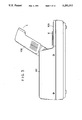
FIG. 1 is a lateral view of an image input apparatus embodying the present invention;
FIG. 2 is a front view of said image input apparatus;
FIG. 3 is a lateral view of said image input apparatus with the illumination unit thereof in a lifted state;
FIGS. 4 to 6 are views showing the mode of mounting of a film holder in said image input apparatus;
FIG. 7 is a schematic cross-sectional view, seen from the front direction, showing the structure of a stage driving unit of said image input apparatus;
FIG. 8 is a schematic cross-sectional view, seen from the front direction, showing the structure of an optical system in said image input apparatus;
FIG. 9 is a schematic cross-sectional view, seen from the lateral direction, showing the structures shown in FIGS. 7 and 8;
FIGS. 10 and 11 are schematic cross-sectional views of said image input apparatus with the illumination unit thereof in a closed state, seen from the front direction;
FIG. 12 is a partial magnified view of Fig. 11;
FIG. 13 is a comparative view showing the function of the illumination unit of said image input apparatus; and
FIGS. 14 and 15 are external perspective views of a conventional image input apparatus.
DETAILED DESCRIPTION OF THE PREFERRED EMBODIMENTS
FIGS. 1 to 3 illustrate an image input apparatus embodying the present invention, respectively in a lateral view, a front view and a lateral view with the illumination unit thereof in a lifted state.
Said apparatus is principally composed of a main body 101 and an illumination unit 102, which is popped up by sliding an illumination pop-up lever 1 in the lateral direction, and which stops at an angle as shown in FIG. 3. Such mechanism can be realized by already known technology.
A stage 6 for mounting a film holder 4 is provided on a horizontal surface 103, which is revealed when the illumination unit 102 is popped up.
The horizontal surface 103 need not be precisely horizontal, nor be precisely planar.
FIGS. 4 to 6 illustrate the mode of mounting of the film holder 4 on the stage 6.
The stage 6 is provided with a light-transmitting window 6a, and the film holder 4 is also provided with a window 4a.
The film holder 4 is so constructed as to sandwich a film original 5 therein, whereupon an image frame thereof is exposed in the window 4a.
The film holder 4 supporting the film original 5 is mounted on the stage 6 as shown in FIG. 5, in such a manner that the windows 4a and 6a mutually overlap. Then the illumination unit 102 is pressed down to a closed state shown in FIG. 6.
When the illumination unit 102 is closed, the film holder is enclosed by the horizontal surface 103 and the illumination unit 102, whereby the film original 5 supported in the film holder 4 and exposed in the window 4a thereof is shielded from the external light.
In the image input operation is initiated without closing the illumination unit 102, the amount of light becomes deficient since the illumination unit 102 is separated from the film original 5 so that the light from said unit 102 does not reach the film original. Such state may be identified from the output of a CCD line sensor 10 (to be discussed later), and there may be provided an alarm for an error state.
Also the mounting operation of the film holder 4 onto the stage 6 is facilitated since said stage 6 is provided on the horizontal surface 103.
In case the film original 5 is long, the end portions thereof appear from the sides of the illumination unit 102 as shown in FIG. 6, but this fact does not affect the function or performance of the apparatus. Consequently, even a long film original need not be cut or wound at the mounting.
FIG. 7 is a schematic cross-sectional view, seen from the front direction, showing the structure of a stage driving unit provided under the stage 6 in the main body 101.
Referring to FIG. 7, a lead screw mechanism 11 is driven, through a motor joint 22, by a stepping motor 12 controlled by a control system (not shown), whereby the stage 6 moves in the lateral direction as indicated by a double arrow.
Said stage 6 driven by said lead screw mechanism 11 moves on a linear guide mechanism 13, which precludes any movement other than that in the lateral direction in FIG. 7, such as might result from insufficient precision of manufacture of the lead screw mechanism 11.
FIG. 8 is a schematic cross-sectional view, seen from the front direction, showing a structure for focusing the image of the film original 5 onto the CCD line sensor 10, by means of transmissive illumination.
FIG. 9 is a cross-sectional view, seen from the lateral direction, showing the structures shown in FIGS. 7 and 8.
As shown in FIG. 9, the mechanism shown in FIG. 7 and the optical system shown in FIG. 8 are both positioned on a scanning block 20 provided on a frame 15.
Referring to FIGS. 8 and 9, a lamp unit 8 provided in the illumination unit 102 is composed of a linear cylindrical light source, and, in the lower face of the illumination unit 102 there is provided a slit 104 for transmitting the light from said lamp unit 8. The light transmitted by said slit 104 illuminates a part of the film original 5 exposed in the window 4a of the film holder 4 mounted on the stage 6. The light transmitted by said film original 5 enters the main body 101 through the window 6a of the stage 6, is then reflected by a 45° mirror 19, and then focused on the CCD line sensor 10 by a projection optical system 9.
In the above-explained configuration, the mechanism shown in FIG. 7 moves the stage 6 during the illumination by the lamp unit 8, whereby a frame of film original 5, exposed in the window 4a of the film holder 4, succession is scanned in succession, and each line of the image is focused in succession on the CCD line sensor 10 to eventually enter the entire image.
The stage 6 is moved for example in the following manner. At the start of the image input operation, the stage 6 is moved to the right in such a manner that the left-hand end of the film image frame, exposed in the window 4a of the film holder 4, is positioned below the slit 104. The stage is then moved to the left after the start of the image input operation, and is stopped when the right-hand end of said image frame of the film original 5 passes under said slit 104.
The image lines focused on the CCD line sensor 10 are converted into electrical signals, which are then subjected to signal processing such as amplification and correction.
FIGS. 10 and 11 are schematic cross-sectional views, seen from the front direction, of a state with the illumination unit 102 in the closed state. The illumination unit pop-up lever 1 is shown in FIG. 10 but not in FIG. 11.
Referring to FIG. 10, said pop-up lever 1 is biased to the right by an unillustrated spring, thereby engaging with a lever key 3 and maintaining the illumination unit 102 in the closed state. By a sliding motion of said pop-up lever 1 to the left, the lever key 3 is liberated and the illumination unit 102 pops up.
When the illumination unit 102 is in the closed state, the force applied to the pop-up lever 1 is also applied to the lever key 3, whereby the position of illumination unit 102 tends to vary with respect to the stage 6, and the amount of light received by the CCD line sensor 10 fluctuates due to the unstable positioning of the lamp unit 8. Such phenomenon also occurs as a result of play in the connection between the illumination unit 102 and the main body 101.
Therefore, in order to stabilize the position of the lamp unit 8, the lever key 3 is provided with a guide pin 21 and the frame 16 of the main body 101 is provided with a guide 16a, as shown in FIG. 11. FIG. 12 is a partial view in the vicinity of the lever key 3 shown in FIG. 11. With such structure, the guide pin 21 of the lever key 3 is guided by the guide 16a when the illumination unit 102 is closed. When the pop-up lever 1 engages with the lever key 3, it receives a force to the right, but the position of the illumination unit 102 in the lateral direction is stabilized since the movement in said lateral direction is limited by said guide 16a and guide pin 21.
FIG. 13 is a view of a comparative structure of a circled part C in FIG. 11. The movement of the stage 6 causes lateral movement of the film original 5, and, with a movement to the right when the right-hand end of the film original 5 is positioned as shown in FIG. 11, said right-hand end of the film original may be caught by an illumination cover 2 in the structure shown in FIG. 13. Such an occurrence may damage the film original 5 or cause movement of the film original 5 in the film holder 4.
For this reason, the right- and left-hand ends of an illuminating frame 14 are bent downwards, and the film original 5 is therefore guided by the face of the thus bent frame and is no longer caught by the illumination cover 2.

Claims (4)

What is claimed is:
1. An image input apparatus which reads a film original to input an image of the film original, comprising:
a main body portion;
a stage provided on a substantially horizontal surface of said main body portion and adapted to detachably support the film original;
means for effecting horizontal scanning movement of said stage;
an illumination unit including light source means for effecting transmissive illumination of the film original supported on said stage, and a light-shielding cover;
a light sensor provided in said main body portion; and
an optical system provided in said main body portion for directing to said light sensor light transmitted from said light source means through the film original supported on said stage;
said illumination unit being displaceable between a first position close to said horizontal surface and in which said light source means effects the transmissive illumination of the film original in association with the scanning movement of said stage and also in which said light-shielding cover shields said stage from external light, and a second position raised from said horizontal surface to enable mounting of the film original on said stage.
2. An image input apparatus according to claim 1, further comprising alarm means for alarming when reading of the film original is attempted with said illumination unit not at said first position.
3. An image input apparatus according to claim 1, wherein said illumination unit has locating means for locating said illumination unit at a same predetermined position relative to said main body portion each time said illumination unit is brought to said first position.
4. An image input apparatus according to claim 1, wherein said stage is adapted to detachably support a film holder for mounting the film original.
US07/749,551 1990-08-29 1991-08-23 Transmissive illumination type image input apparatus Expired - Lifetime US5291312A (en)

Applications Claiming Priority (2)

Application Number Priority Date Filing Date Title
JP2-227082 1990-08-29
JP2227082A JPH04109748A (en) 1990-08-29 1990-08-29 Picture input device

Publications (1)

Publication Number Publication Date
US5291312A true US5291312A (en) 1994-03-01

Family

ID=16855228

Family Applications (1)

Application Number Title Priority Date Filing Date
US07/749,551 Expired - Lifetime US5291312A (en) 1990-08-29 1991-08-23 Transmissive illumination type image input apparatus

Country Status (3)

Country Link
US (1) US5291312A (en)
EP (1) EP0474111A3 (en)
JP (1) JPH04109748A (en)

Cited By (1)

* Cited by examiner, † Cited by third party
Publication number Priority date Publication date Assignee Title
US5585937A (en) * 1993-04-21 1996-12-17 Mitsubishi Denki Kabushiki Kaisha Image reading device for percisely moving optical components to provide relatively reduced and magnified images

Citations (8)

* Cited by examiner, † Cited by third party
Publication number Priority date Publication date Assignee Title
DE2336366A1 (en) * 1973-07-17 1975-02-13 System Service Gmbh Microfilm reception and remote read-out system - uses TV camera to convert film recordings into video signals for a transmission
EP0149196A2 (en) * 1983-12-30 1985-07-24 Fuji Photo Film Co., Ltd. Method of and apparatus for producing video signal associated with photographic image
US4660091A (en) * 1985-09-16 1987-04-21 Eastman Kodak Company Exposure level correction for film-to-video conversion
US4751582A (en) * 1985-07-24 1988-06-14 Kabushiki Kaisha Toshiba Office machine having clamshell structure
US4814798A (en) * 1987-06-09 1989-03-21 Kentek Information Systems, Inc. Combined electrographic printer, copier, and telefax machine with duplex capability
AT389965B (en) * 1981-05-06 1990-02-26 Sony Corp IMAGE TRANSFORMER
US4996604A (en) * 1987-07-31 1991-02-26 Tokyo Electric Co., Ltd. Image scanner
US5113268A (en) * 1988-06-10 1992-05-12 Minolta Camera Kabushiki Kaisha Dual operational image reading apparatus

Family Cites Families (1)

* Cited by examiner, † Cited by third party
Publication number Priority date Publication date Assignee Title
JPH0358664A (en) * 1989-07-27 1991-03-13 Olympus Optical Co Ltd Film scanner

Patent Citations (8)

* Cited by examiner, † Cited by third party
Publication number Priority date Publication date Assignee Title
DE2336366A1 (en) * 1973-07-17 1975-02-13 System Service Gmbh Microfilm reception and remote read-out system - uses TV camera to convert film recordings into video signals for a transmission
AT389965B (en) * 1981-05-06 1990-02-26 Sony Corp IMAGE TRANSFORMER
EP0149196A2 (en) * 1983-12-30 1985-07-24 Fuji Photo Film Co., Ltd. Method of and apparatus for producing video signal associated with photographic image
US4751582A (en) * 1985-07-24 1988-06-14 Kabushiki Kaisha Toshiba Office machine having clamshell structure
US4660091A (en) * 1985-09-16 1987-04-21 Eastman Kodak Company Exposure level correction for film-to-video conversion
US4814798A (en) * 1987-06-09 1989-03-21 Kentek Information Systems, Inc. Combined electrographic printer, copier, and telefax machine with duplex capability
US4996604A (en) * 1987-07-31 1991-02-26 Tokyo Electric Co., Ltd. Image scanner
US5113268A (en) * 1988-06-10 1992-05-12 Minolta Camera Kabushiki Kaisha Dual operational image reading apparatus

Cited By (2)

* Cited by examiner, † Cited by third party
Publication number Priority date Publication date Assignee Title
US5585937A (en) * 1993-04-21 1996-12-17 Mitsubishi Denki Kabushiki Kaisha Image reading device for percisely moving optical components to provide relatively reduced and magnified images
US5724159A (en) * 1993-04-21 1998-03-03 Mitsubishi Denki Kabushiki Kaisha Image reading device provided with structural features for fixing the reading unit during transport

Also Published As

Publication number Publication date
JPH04109748A (en) 1992-04-10
EP0474111A2 (en) 1992-03-11
EP0474111A3 (en) 1992-10-21

Similar Documents

Publication Publication Date Title
US5115308A (en) Image processing apparatus
JP2925838B2 (en) Image reading device
JP3141375B2 (en) Image reading apparatus and image reading method
US5420700A (en) Image conversion apparatus having scanning mechanism and optical system on single base
US5291312A (en) Transmissive illumination type image input apparatus
EP0115366A2 (en) Device for optically scanning a document
US7110149B2 (en) Carriage module for scanner
JPH0358664A (en) Film scanner
US4937683A (en) Image recording apparatus
JP2545255B2 (en) Micro film reader
JPH0756242A (en) Image reading unit
JP2899305B2 (en) Image scanner
JP3150037B2 (en) Carrier drive mechanism
JP3231838B2 (en) Image reading device
JP3149936B2 (en) Image reading unit
JP2000278488A5 (en)
JPH01241533A (en) Microimage processor
US5877847A (en) Exposure device
JP2814114B2 (en) Transparent original reading device and transparent original holding member
JP2545853Y2 (en) Light intensity correction mechanism of copier
JP3713104B2 (en) Variable magnification optical device
JP3109096B2 (en) Image scanner
JP3444968B2 (en) Dust-proof structure for micro-width original reader
EP0517007A1 (en) Facsimile device
JPH0682930A (en) Image reading unit

Legal Events

Date Code Title Description
AS Assignment

Owner name: NIKON CORPORATION A CORPORATION OF JAPAN, JAPAN

Free format text: ASSIGNMENT OF ASSIGNORS INTEREST.;ASSIGNORS:AIKAWA, TOSHIYA;MAEDA, EISAKU;YOSHIZAWA, SATORU;REEL/FRAME:005830/0342

Effective date: 19910821

STCF Information on status: patent grant

Free format text: PATENTED CASE

FEPP Fee payment procedure

Free format text: PAYOR NUMBER ASSIGNED (ORIGINAL EVENT CODE: ASPN); ENTITY STATUS OF PATENT OWNER: LARGE ENTITY

FPAY Fee payment

Year of fee payment: 4

FPAY Fee payment

Year of fee payment: 8

FPAY Fee payment

Year of fee payment: 12