US5292291A - Parallel-axis gear differential with extended planet gears - Google Patents
Parallel-axis gear differential with extended planet gears Download PDFInfo
- Publication number
- US5292291A US5292291A US07/890,565 US89056592A US5292291A US 5292291 A US5292291 A US 5292291A US 89056592 A US89056592 A US 89056592A US 5292291 A US5292291 A US 5292291A
- Authority
- US
- United States
- Prior art keywords
- housing
- pockets
- gear
- gears
- side gears
- Prior art date
- Legal status (The legal status is an assumption and is not a legal conclusion. Google has not performed a legal analysis and makes no representation as to the accuracy of the status listed.)
- Expired - Lifetime
Links
Images


Classifications
-
- F—MECHANICAL ENGINEERING; LIGHTING; HEATING; WEAPONS; BLASTING
- F16—ENGINEERING ELEMENTS AND UNITS; GENERAL MEASURES FOR PRODUCING AND MAINTAINING EFFECTIVE FUNCTIONING OF MACHINES OR INSTALLATIONS; THERMAL INSULATION IN GENERAL
- F16H—GEARING
- F16H48/00—Differential gearings
- F16H48/20—Arrangements for suppressing or influencing the differential action, e.g. locking devices
- F16H48/28—Arrangements for suppressing or influencing the differential action, e.g. locking devices using self-locking gears or self-braking gears
- F16H48/285—Arrangements for suppressing or influencing the differential action, e.g. locking devices using self-locking gears or self-braking gears with self-braking intermeshing gears having parallel axes and having worms or helical teeth
Definitions
- the invention relates to automotive differentials having planetary gear arrangements that are mounted in a housing for connecting an input drive shaft to a pair of output drive shafts.
- Gear differentials include compound planetary gear sets carried within a differential housing interconnecting a pair of output shafts for opposite directions of rotation with respect to the housing.
- An input shaft is connected to the housing for rotating the housing about a common axis of the output shafts.
- Sun gear members of the respective planetary gear sets also referred to as “side” gears, are coupled to inner ends of the output shafts.
- Planet gear members of the planetary gear sets also referred to as “element” gears, operatively connect the two side gears for relative rotation in opposite directions.
- One known arrangement of the planetary gearing positions the sun and planet gears within the housing for rotation about axes that extend parallel to each other. Differentials with this type of gearing arrangement are referred to as "parallel-axis" gear differentials.
- the planet gears of this type of differential are generally mounted in pairs within the differential housing. One portion of each planet gear meshes with one of the side gears, and another portion of each planet gear meshes with its paired planet gear.
- the planet gears are individually supported for rotation on shafts or within pockets formed in the housings.
- the pockets provide bearings for slidably supporting outside cylinder surfaces of the planet gears including the top lands of the planet gear teeth.
- bores formed in the housing can be used to support opposite ends of the shafts.
- the planet gear pairs are evenly distributed about the central axis of the differential.
- the pockets supporting the element gears occupy most of the circumference of the housing, leaving little room between the pairs of pockets to form window passages through the housing to circulate lubricant or to gain access to the interior of the housing.
- the remaining portions of the housing between the pairs of pockets are important for preserving structural strength of the housing.
- the side gears are positioned together between the straddled combination gear meshes, and this limits access to space between the side gears for fastening ends of the output shafts within the differential or for connecting a coaxial input shaft to the differential housing.
- relative sliding between the two side gears can produce different frictional effects between opposite directions of torque transfer through the differential housing (e.g. "drive” and “coast” directions).
- the opposite directions of torque transfer thrust the side gears either together or apart against opposite ends of the housing.
- the relative sliding velocity between the side gears is twice as great as the relative sliding velocity between either side gear and the housing.
- My invention improves parallel-axis gear differentials by providing better access to the interior of their housings for such purposes as circulating lubricant, fastening output shafts within the housings, or connecting coaxial input shafts to the housings.
- One example of my new parallel-axis gear differential includes a housing that is rotatable about a pair of output drive shafts.
- a pair of side gears is arranged to receive ends of the respective output shafts for rotation with the output shafts about a common axis.
- Three pairs of combination gears form respective gear trains interconnecting the side gears for opposite directions of relative rotation.
- Each combination gear includes a first gear section in meshing engagement with one of the side gears, a second gear section in meshing engagement with its paired combination gear, and a stem section interconnecting the first and second gear sections.
- Each of the pockets includes a first bearing portion rotatively supporting the first gear section, a second bearing portion rotatively supporting the second gear section, and an intermediate portion providing clearance for the stem section.
- a window is formed as a passageway in the housing connecting an exterior of the housing to the intermediate portion of the pockets for providing access to an interior of the housing.
- each pair of pockets overlap each other along the common axis through a first distance that corresponds to a second distance through which the side gears are separated from one another.
- the stem sections of the combination gears extend through a third distance that is approximately equal to the sum of a face width of one of the side gears and either of the first and second distances.
- the window is dimensioned in length along the common axis through a fourth distance that also corresponds to the first and second distances.
- Another example of my invention includes a similar differential assembly having stem sections of the combination gears overlapping through a first distance along the common axis.
- the side gears are spaced apart through the same distance.
- a driving block is mounted in the housing between the side gears for connecting a coaxial input shaft to the housing.
- An inner portion of the driving block is keyed to the input shaft and an outer portion of the same block is keyed to the housing.
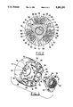
- FIG. 1 is a longitudinal sectional view of one example of my differential interconnecting an input drive shaft to two output drive shafts.
- FIG. 2 is a traverse sectional view taken along line 2--2 of FIG. 1 showing an end view of one of two housing halves.
- FIG. 3 is an exploded view of the one housing half and a driving block also shown in FIG. 2.
- FIG. 4 is a longitudinal sectional view of another example of my differential arranged for fastening two output drive shafts within a housing.
- my differential is constructed as a center differential for delivering drive power to front and rear axles of a vehicle.
- the center differential is assembled from two housing halves 10 and 12 that are held together by bolts 14 extending through respective bores 16 and 18 in the two housing halves 10 and 12.
- An input shaft 46 extends through a bore 48 in output shaft 28 for connecting the housing halves 10 and 12 to a source of drive power (not shown).
- An inner end of the input shaft 46 is keyed to an inner portion of driving block 50 by mating splines 52.
- Keys 54 shown in FIGS. 2 and 3, project from an outer portion of the driving block 50 for engaging mating keyways 56 formed in adjacent portions of the housing halves 10 and 12.
- the keys 54 and mating keyways 56 align the housing halves in desired relative angular positions about the common axis 40.
- Side gears 58 and 60 which are preferably helical gears, are keyed to inner ends of the respective output shafts 28 and 30 by splines 62 and 64.
- Three pairs of combination gears 66 and 68 are mounted in mesh about the side gears 58 and 60 in equal angular positions about the common axis 40.
- Each of the combination gears 66 and 68 includes a first gear section 70 in mesh with one of the side gears, a second gear section 72 in mesh with the first gear section 70 of its paired combination gear, and a stem section 74 interconnecting the first and second gear sections 70 and 72. Further description of this type of combination gear can be found in commonly assigned copending U.S. patent application Ser. No. 735,821, filed Jul. 25, 1991; and this application is hereby incorporated by reference for all of its relevant description.
- Each of the pockets includes a first bearing portion 84 for rotationally supporting the first gear sections 70, a second bearing portion 84 for rotationally supporting the second gear sections 72, and an intermediate portion 88 providing clearance for the stem sections 74.
- the side gears 58 and 60 are spaced apart along the common axis by the driving block 50 through substantially the same distance.
- the stem sections 74 of each combination gear extend in length through a distance substantially equal to the sum of the spacing between side gears and a face width of the side gear in mesh with its paired combination gear.
- Three windows 90 are formed through respective exterior surfaces 92 and 94 of the housing halves 10 and 12, constituting passages connecting the intermediate portions 88 of the pockets to the exterior surfaces 92 and 94.
- the windows 90 allow for improved circulation of lubricant from an exterior sump (not shown) to bearing supports and meshes of the side and combination gears.
- the windows 90 can be sized to a maximum length in the direction of the common axis 40 equal to the distance through which the intermediate portions 88 of the pairs of pockets overlap each other, without diminishing areas over which the first and second bearing portions 84 and 86 are effective for rotationally supporting the gear sections of the combination gears.
- the windows 90 can be dimensioned in circumference about the common axis 40 through a combined angular spacing of the pairs of pockets 76 and 78, without adversely weakening housing strength.
- the driving block 50 has opposite side surfaces 96 and 98 for resisting end thrust from the side gears 58 and 60. Relative rotational speed between each of the side gears and the driving block is equal to one-half of the relative rotational speed between the side gears. This reduces the amount of heat generated at respective inner end faces 100 and 102 of the side gears 58 and 60.
- the driving block 50 allows the coefficient of friction between the respective inner end faces 100 and 102 of the side gears and the opposite side surfaces 96 and 98 of the driving block to be controlled independently of the coefficient of friction between the inner end faces of the side gears alone.
- the coefficient of friction between the driving block and side gears can be either the same as or different from the coefficient of friction between the side gears and the respective housing halves (notwithstanding effects of thrust washer 104, which is regarded as either a part of side gear 60 or housing half 12).
- FIG. 4 A second embodiment of my invention is illustrated in FIG. 4 as a front or rear differential for dividing drive power between front or rear drive axle halves.
- a housing 110 is fitted with an end cap 112, and the housing 110 and end cap 112 are secured together by bolts 114.
- a flange 116 is formed integrally With the housing 110 for mounting a ring gear (not shown).
- Bearings 118 and 120 which are mounted within respective trunnions 122 and 124, support the housing for rotation about axle shafts 126 and 128.
- a planetary gear arrangement similar to the preceding embodiment is carried in the housing 110.
- side gears 130 and 132 are splined to inner ends of the axle shafts 126 and 128 for rotation about a common axis 135.
- Combination gears 134 are mounted in respective pairs of pockets 136 that are evenly distributed about the periphery of the side gears.
- Each combination gear 134 includes a first gear section 138 for meshing with one of the side gears, a second gear section 140 for meshing with the first gear section 138 of its paired combination gear, and a stem section 142 interconnecting the two gear sections 138 and 140.
- each pocket 136 includes a first bearing portion 144 for rotationally supporting the first gear sections 138, a second bearing portion 146 for rotationally supporting the second gear sections 140, and an intermediate portion 148 providing clearance for the stem sections 142.
- the side gears 130 and 132 are separated along the common axis of rotation 135 by a removable spacing block 150 through a distance that substantially corresponds to an amount of overlap between the stem sections 142 of the combination gear pairs.
- a removable spacing block 150 is depicted with a particular design, a variety of other designs of spacing blocks could also be used including spacing blocks disclosed in U.S. Pat. Nos. 3,494,226; 4,365,524; 4,495,835; and 4,677,876.
- each pair of pockets 136 also overlap in a direction along the common axis through substantially the same distance overlapped by the stem sections 142.
- Windows 152 are formed through this overlapping space in the housing connecting an exterior 154 of the housing to the intermediate portions 148.
- the windows 152 are dimensioned to permit insertion and removal of the spacing block 150 (upon removal of a pair of combination gears) to provide access to removable locking elements 156 formed as so-called "C-lock" washers on inner ends of the axle shafts 126 and 128.
- the locking elements 156 capture the ends of the axle shafts within recesses 158 formed in the side gears 130 and 132 and can be installed or removed through the windows 152.
- the windows 152 also cooperate with passages 158 and 160 that are respectively formed through a flange end of the housing 110 and through end cap 112 for circulating lubricant through the pockets 136.
- Gear meshes between the combination gears 134 and side gears 130 and 132 help to further circulate the lubricant to interior portions of the housing.
Abstract
Description
Claims (22)
Priority Applications (4)
| Application Number | Priority Date | Filing Date | Title |
|---|---|---|---|
| US07/890,565 US5292291A (en) | 1992-05-28 | 1992-05-28 | Parallel-axis gear differential with extended planet gears |
| PCT/US1993/004687 WO1993024768A1 (en) | 1992-05-28 | 1993-05-18 | Parallel-axis gear differential with extended planet gears |
| CA002135478A CA2135478A1 (en) | 1992-05-28 | 1993-05-18 | Parallel-axis gear differential with extended planet gears |
| DE4392514T DE4392514T1 (en) | 1992-05-28 | 1993-05-18 | Parallel axis gear differential with extended planetary gears |
Applications Claiming Priority (1)
| Application Number | Priority Date | Filing Date | Title |
|---|---|---|---|
| US07/890,565 US5292291A (en) | 1992-05-28 | 1992-05-28 | Parallel-axis gear differential with extended planet gears |
Publications (1)
| Publication Number | Publication Date |
|---|---|
| US5292291A true US5292291A (en) | 1994-03-08 |
Family
ID=25396840
Family Applications (1)
| Application Number | Title | Priority Date | Filing Date |
|---|---|---|---|
| US07/890,565 Expired - Lifetime US5292291A (en) | 1992-05-28 | 1992-05-28 | Parallel-axis gear differential with extended planet gears |
Country Status (4)
| Country | Link |
|---|---|
| US (1) | US5292291A (en) |
| CA (1) | CA2135478A1 (en) |
| DE (1) | DE4392514T1 (en) |
| WO (1) | WO1993024768A1 (en) |
Cited By (20)
| Publication number | Priority date | Publication date | Assignee | Title |
|---|---|---|---|---|
| US5346443A (en) * | 1993-02-23 | 1994-09-13 | Zexel-Gleason Usa, Inc. | Parallel-axis gear differential with limited edge contact between gear members |
| US5389048A (en) * | 1993-03-24 | 1995-02-14 | Zexel-Gleason Usa, Inc. | Parallel-axis differential with triplet combination gears |
| US5415599A (en) * | 1993-05-06 | 1995-05-16 | Zexel-Gleason Usa, Inc. | Gear mounting system for differential |
| US5433673A (en) * | 1993-05-06 | 1995-07-18 | Zexel Torsen Inc. | Differential with pivotable gear mountings |
| US5492510A (en) * | 1994-10-21 | 1996-02-20 | Zexel Torsen Inc. | Differential with extended planet gears having multiple meshing portions |
| US5545104A (en) * | 1995-02-06 | 1996-08-13 | Tilley; Michael J. | Automotive sun gear/planetary housing assembly |
| US5554081A (en) * | 1995-03-08 | 1996-09-10 | Zexel Torsen Inc. | Differential with distributed planet gears |
| US5624346A (en) * | 1994-06-23 | 1997-04-29 | Tochigi Fuji Sangyo Kabushiki Kaisha | Differential gear |
| US5632704A (en) * | 1994-05-30 | 1997-05-27 | Tochigi Fuji Sangyo Kabushiki Kaisha | Differential apparatus |
| US5647815A (en) * | 1995-09-05 | 1997-07-15 | Zexel Torsen Inc. | Differential with bias control |
| US5669844A (en) * | 1994-11-16 | 1997-09-23 | Toyota Jidosha Kabushiki Kaisha | Lubrication system for a parallel-axis differential |
| US6066064A (en) * | 1998-03-06 | 2000-05-23 | Zexel Corporation | Parallel-axis combination differential gear unit |
| US6083133A (en) * | 1998-05-08 | 2000-07-04 | Zexel Torsen Inc. | Bevel gear differential with asymmetrically distributed pinions |
| US20050197229A1 (en) * | 2004-03-05 | 2005-09-08 | Valente Paul J. | Helical gear differential |
| DE19539169B4 (en) * | 1994-10-21 | 2006-09-21 | Toyoda Machine Works, Ltd., Kariya | Differential with extended planetary gears with multiple engagement sections |
| US20080220926A1 (en) * | 2005-09-14 | 2008-09-11 | Jose Gimenez Vidal | Differential for Vehicles |
| US20090019966A1 (en) * | 2007-07-20 | 2009-01-22 | American Axle & Manufacturing, Inc. | Pre-load mechanism for helical gear differential |
| US7611437B2 (en) | 2004-03-05 | 2009-11-03 | American Axle & Manufacturing, Inc. | Spacer pin arrangement for helical gear differential |
| US20100081535A1 (en) * | 2008-09-30 | 2010-04-01 | Peter Gutsmiedl | Parallel-axis helical differential assembly |
| DE19616807B4 (en) * | 1995-05-01 | 2015-04-30 | Toyoda Machine Works, Ltd. | Lubrication system for a parallel-axis differential |
Families Citing this family (1)
| Publication number | Priority date | Publication date | Assignee | Title |
|---|---|---|---|---|
| JPH10227348A (en) * | 1997-02-14 | 1998-08-25 | Zexel:Kk | Parallel shaft differential gear |
Citations (31)
| Publication number | Priority date | Publication date | Assignee | Title |
|---|---|---|---|---|
| US1195314A (en) * | 1916-08-22 | Difeeeential gearing | ||
| US1938649A (en) * | 1931-06-05 | 1933-12-12 | George I Welsh | Differential gear for vehicles |
| US2269734A (en) * | 1939-09-18 | 1942-01-13 | Lyman S Powell | Differential |
| US2651215A (en) * | 1951-03-03 | 1953-09-08 | Dualoc Engineering Co | Nontorque-equalizing differential transmission |
| US2789446A (en) * | 1952-08-18 | 1957-04-23 | Dualoc Engineering Co | Variable-torque distributing transmissions |
| US2972265A (en) * | 1958-04-23 | 1961-02-21 | Walter Maurice | Differential mechanism for motor vehicles |
| US3095761A (en) * | 1959-12-21 | 1963-07-02 | Hilado Alfonso | Self locking differential mechanism |
| US3154969A (en) * | 1963-04-30 | 1964-11-03 | Illinois Tool Works | Semi-locking differential |
| US3251244A (en) * | 1962-02-02 | 1966-05-17 | Claude H Nickell | Torque divided hydraulically proportioned output differential |
| US3494226A (en) * | 1968-06-24 | 1970-02-10 | Findlay A Carter | Power transmission assembly |
| US3706239A (en) * | 1971-02-09 | 1972-12-19 | Boise Cascade Corp | Pinion differential mechanism having internal bias torque |
| US4245524A (en) * | 1978-11-08 | 1981-01-20 | Fairfield Manufacturing Company | Steering differential |
| US4365524A (en) * | 1980-09-05 | 1982-12-28 | Tractech, Inc. | Torque-proportioning differential with wedge block thrust bearing means |
| JPS5997346A (en) * | 1982-11-24 | 1984-06-05 | Komatsu Ltd | Differential device of car |
| US4491035A (en) * | 1983-03-15 | 1985-01-01 | The Gleason Works | Differential gear apparatus |
| US4491036A (en) * | 1983-03-15 | 1985-01-01 | The Gleason Works | Differential assembly having means for accommodating angular misalignments of axle segments |
| EP0130806A2 (en) * | 1983-07-01 | 1985-01-09 | Rodney Trevor Quaife | Differential mechanism |
| US4495835A (en) * | 1983-03-15 | 1985-01-29 | The Gleason Works | Differential gearing assembly |
| US4512211A (en) * | 1983-03-15 | 1985-04-23 | The Gleason Works | Differential assembly having means for locking and positioning axle shafts therein |
| WO1986004127A1 (en) * | 1984-12-28 | 1986-07-17 | Jack Knight (Developments) Limited | Differentials |
| US4677876A (en) * | 1984-02-13 | 1987-07-07 | Tractech, Inc. | Torque-proportioning differential with cylindrical spacer |
| FR2615262A1 (en) * | 1987-05-11 | 1988-11-18 | Lecal Roger | Differential link with double distribution of torque |
| US4890511A (en) * | 1987-10-22 | 1990-01-02 | D-K Gleason, Inc. | Friction reduction in a differential assembly |
| EP0388207A2 (en) * | 1989-03-15 | 1990-09-19 | Kabushiki Kaisha Toshiba | Transmission apparatus |
| US4969532A (en) * | 1987-11-04 | 1990-11-13 | Fuji Jukogyo Kabushiki Kaisha | Central differential for a four-wheel drive motor vehicle |
| GB2234791A (en) * | 1989-06-24 | 1991-02-13 | Gkn Automotive Ag | Differential gearing with asymmetrically distributed differential gears |
| DE4013196A1 (en) * | 1990-04-25 | 1991-10-31 | Viscodrive Gmbh | Differential gear with housing - contain differential cage with toothed driven wheels coupled by compensating wheels |
| DE4013201A1 (en) * | 1990-04-25 | 1991-10-31 | Viscodrive Gmbh | Differential gear with housing - has differential cage inside it with driven wheels coupled by equalising wheels |
| EP0482754A1 (en) * | 1990-10-24 | 1992-04-29 | Zexel-Gleason Usa, Inc. | Differential with varied frictional surfaces |
| US5122101A (en) * | 1991-07-25 | 1992-06-16 | Zexel-Gleason Usa, Inc. | Parallel-axis combination gear differential |
| US5169370A (en) * | 1991-07-25 | 1992-12-08 | Zexel-Gleason Usa, Inc. | End-thrust design for parallel-axis differential |
Family Cites Families (2)
| Publication number | Priority date | Publication date | Assignee | Title |
|---|---|---|---|---|
| DE1169245B (en) * | 1960-11-29 | 1964-04-30 | Alfonso Hilado | Self-locking differential gear with worm gear |
| DE4027422C2 (en) * | 1990-08-30 | 1994-02-10 | Gkn Automotive Ag | Method and device for changing the blocking value |
-
1992
- 1992-05-28 US US07/890,565 patent/US5292291A/en not_active Expired - Lifetime
-
1993
- 1993-05-18 DE DE4392514T patent/DE4392514T1/en not_active Ceased
- 1993-05-18 CA CA002135478A patent/CA2135478A1/en not_active Abandoned
- 1993-05-18 WO PCT/US1993/004687 patent/WO1993024768A1/en active Application Filing
Patent Citations (32)
| Publication number | Priority date | Publication date | Assignee | Title |
|---|---|---|---|---|
| US1195314A (en) * | 1916-08-22 | Difeeeential gearing | ||
| US1938649A (en) * | 1931-06-05 | 1933-12-12 | George I Welsh | Differential gear for vehicles |
| US2269734A (en) * | 1939-09-18 | 1942-01-13 | Lyman S Powell | Differential |
| US2651215A (en) * | 1951-03-03 | 1953-09-08 | Dualoc Engineering Co | Nontorque-equalizing differential transmission |
| US2789446A (en) * | 1952-08-18 | 1957-04-23 | Dualoc Engineering Co | Variable-torque distributing transmissions |
| US2972265A (en) * | 1958-04-23 | 1961-02-21 | Walter Maurice | Differential mechanism for motor vehicles |
| US3095761A (en) * | 1959-12-21 | 1963-07-02 | Hilado Alfonso | Self locking differential mechanism |
| US3251244A (en) * | 1962-02-02 | 1966-05-17 | Claude H Nickell | Torque divided hydraulically proportioned output differential |
| US3154969A (en) * | 1963-04-30 | 1964-11-03 | Illinois Tool Works | Semi-locking differential |
| US3494226A (en) * | 1968-06-24 | 1970-02-10 | Findlay A Carter | Power transmission assembly |
| US3706239A (en) * | 1971-02-09 | 1972-12-19 | Boise Cascade Corp | Pinion differential mechanism having internal bias torque |
| US4245524A (en) * | 1978-11-08 | 1981-01-20 | Fairfield Manufacturing Company | Steering differential |
| US4365524A (en) * | 1980-09-05 | 1982-12-28 | Tractech, Inc. | Torque-proportioning differential with wedge block thrust bearing means |
| JPS5997346A (en) * | 1982-11-24 | 1984-06-05 | Komatsu Ltd | Differential device of car |
| US4512211A (en) * | 1983-03-15 | 1985-04-23 | The Gleason Works | Differential assembly having means for locking and positioning axle shafts therein |
| US4491035A (en) * | 1983-03-15 | 1985-01-01 | The Gleason Works | Differential gear apparatus |
| US4491036A (en) * | 1983-03-15 | 1985-01-01 | The Gleason Works | Differential assembly having means for accommodating angular misalignments of axle segments |
| US4495835A (en) * | 1983-03-15 | 1985-01-29 | The Gleason Works | Differential gearing assembly |
| EP0130806A2 (en) * | 1983-07-01 | 1985-01-09 | Rodney Trevor Quaife | Differential mechanism |
| US4677876A (en) * | 1984-02-13 | 1987-07-07 | Tractech, Inc. | Torque-proportioning differential with cylindrical spacer |
| WO1986004127A1 (en) * | 1984-12-28 | 1986-07-17 | Jack Knight (Developments) Limited | Differentials |
| FR2615262A1 (en) * | 1987-05-11 | 1988-11-18 | Lecal Roger | Differential link with double distribution of torque |
| US4890511A (en) * | 1987-10-22 | 1990-01-02 | D-K Gleason, Inc. | Friction reduction in a differential assembly |
| US4969532A (en) * | 1987-11-04 | 1990-11-13 | Fuji Jukogyo Kabushiki Kaisha | Central differential for a four-wheel drive motor vehicle |
| EP0388207A2 (en) * | 1989-03-15 | 1990-09-19 | Kabushiki Kaisha Toshiba | Transmission apparatus |
| GB2234791A (en) * | 1989-06-24 | 1991-02-13 | Gkn Automotive Ag | Differential gearing with asymmetrically distributed differential gears |
| US5055096A (en) * | 1989-06-24 | 1991-10-08 | Gkn Automotive Ag | Differential gearing |
| DE4013196A1 (en) * | 1990-04-25 | 1991-10-31 | Viscodrive Gmbh | Differential gear with housing - contain differential cage with toothed driven wheels coupled by compensating wheels |
| DE4013201A1 (en) * | 1990-04-25 | 1991-10-31 | Viscodrive Gmbh | Differential gear with housing - has differential cage inside it with driven wheels coupled by equalising wheels |
| EP0482754A1 (en) * | 1990-10-24 | 1992-04-29 | Zexel-Gleason Usa, Inc. | Differential with varied frictional surfaces |
| US5122101A (en) * | 1991-07-25 | 1992-06-16 | Zexel-Gleason Usa, Inc. | Parallel-axis combination gear differential |
| US5169370A (en) * | 1991-07-25 | 1992-12-08 | Zexel-Gleason Usa, Inc. | End-thrust design for parallel-axis differential |
Cited By (30)
| Publication number | Priority date | Publication date | Assignee | Title |
|---|---|---|---|---|
| US5346443A (en) * | 1993-02-23 | 1994-09-13 | Zexel-Gleason Usa, Inc. | Parallel-axis gear differential with limited edge contact between gear members |
| US5389048A (en) * | 1993-03-24 | 1995-02-14 | Zexel-Gleason Usa, Inc. | Parallel-axis differential with triplet combination gears |
| US5415599A (en) * | 1993-05-06 | 1995-05-16 | Zexel-Gleason Usa, Inc. | Gear mounting system for differential |
| US5433673A (en) * | 1993-05-06 | 1995-07-18 | Zexel Torsen Inc. | Differential with pivotable gear mountings |
| US5632704A (en) * | 1994-05-30 | 1997-05-27 | Tochigi Fuji Sangyo Kabushiki Kaisha | Differential apparatus |
| US5624346A (en) * | 1994-06-23 | 1997-04-29 | Tochigi Fuji Sangyo Kabushiki Kaisha | Differential gear |
| US5492510A (en) * | 1994-10-21 | 1996-02-20 | Zexel Torsen Inc. | Differential with extended planet gears having multiple meshing portions |
| DE19539169B4 (en) * | 1994-10-21 | 2006-09-21 | Toyoda Machine Works, Ltd., Kariya | Differential with extended planetary gears with multiple engagement sections |
| US5669844A (en) * | 1994-11-16 | 1997-09-23 | Toyota Jidosha Kabushiki Kaisha | Lubrication system for a parallel-axis differential |
| US5545104A (en) * | 1995-02-06 | 1996-08-13 | Tilley; Michael J. | Automotive sun gear/planetary housing assembly |
| US5554081A (en) * | 1995-03-08 | 1996-09-10 | Zexel Torsen Inc. | Differential with distributed planet gears |
| DE19616807B4 (en) * | 1995-05-01 | 2015-04-30 | Toyoda Machine Works, Ltd. | Lubrication system for a parallel-axis differential |
| US5647815A (en) * | 1995-09-05 | 1997-07-15 | Zexel Torsen Inc. | Differential with bias control |
| US6066064A (en) * | 1998-03-06 | 2000-05-23 | Zexel Corporation | Parallel-axis combination differential gear unit |
| US6083133A (en) * | 1998-05-08 | 2000-07-04 | Zexel Torsen Inc. | Bevel gear differential with asymmetrically distributed pinions |
| US7022041B2 (en) | 2004-03-05 | 2006-04-04 | American Axle & Manufacturing, Inc. | Helical gear differential |
| US7611437B2 (en) | 2004-03-05 | 2009-11-03 | American Axle & Manufacturing, Inc. | Spacer pin arrangement for helical gear differential |
| US7147585B2 (en) | 2004-03-05 | 2006-12-12 | American Axle & Manufacturing, Inc. | Helical gear differential |
| US20070037656A1 (en) * | 2004-03-05 | 2007-02-15 | Valente Paul J | Differential assembly |
| US7232399B2 (en) | 2004-03-05 | 2007-06-19 | American Axle & Manufacturing, Inc. | Differential assembly |
| US20050197229A1 (en) * | 2004-03-05 | 2005-09-08 | Valente Paul J. | Helical gear differential |
| US20060128516A1 (en) * | 2004-03-05 | 2006-06-15 | Valente Paul J | Helical gear differential |
| US8057348B2 (en) * | 2005-09-14 | 2011-11-15 | Jose Gimenez Vidal | Differential for vehicles |
| US20080220926A1 (en) * | 2005-09-14 | 2008-09-11 | Jose Gimenez Vidal | Differential for Vehicles |
| US20090019966A1 (en) * | 2007-07-20 | 2009-01-22 | American Axle & Manufacturing, Inc. | Pre-load mechanism for helical gear differential |
| US7837588B2 (en) | 2007-07-20 | 2010-11-23 | American Axle & Manufacturing, Inc. | Pre-load mechanism for helical gear differential |
| US20110015025A1 (en) * | 2007-07-20 | 2011-01-20 | Valente Paul J | Pre-load mechanism for helical gear differential |
| US7976423B2 (en) | 2007-07-20 | 2011-07-12 | American Axle & Manufacturing, Inc. | Pre-load mechanism for helical gear differential |
| US20100081535A1 (en) * | 2008-09-30 | 2010-04-01 | Peter Gutsmiedl | Parallel-axis helical differential assembly |
| US9347542B2 (en) | 2008-09-30 | 2016-05-24 | American Axle & Manufacturing, Inc. | Parallel-axis helical differential assembly |
Also Published As
| Publication number | Publication date |
|---|---|
| CA2135478A1 (en) | 1993-12-09 |
| WO1993024768A1 (en) | 1993-12-09 |
| DE4392514T1 (en) | 1995-04-27 |
Similar Documents
| Publication | Publication Date | Title |
|---|---|---|
| US5292291A (en) | Parallel-axis gear differential with extended planet gears | |
| US5492510A (en) | Differential with extended planet gears having multiple meshing portions | |
| US5122101A (en) | Parallel-axis combination gear differential | |
| US3706239A (en) | Pinion differential mechanism having internal bias torque | |
| US5389048A (en) | Parallel-axis differential with triplet combination gears | |
| US5415601A (en) | Parallel-axis differential with restrained center washer | |
| US4751853A (en) | Differential with equal depth pinion cavities | |
| CA1249140A (en) | Transfer case for vehicle drivetrains | |
| US5682799A (en) | External cylindrical gearing | |
| US5472385A (en) | Differential | |
| US5295923A (en) | Lubrication modification for parallel-axis differential | |
| US4723464A (en) | Differential gear assembly for motor vehicles | |
| US5310389A (en) | Parallel-axis differential gear tooth modification | |
| GB2153930A (en) | Torque-proportioning differential with cylindrical spacer | |
| JP3286810B2 (en) | Helical differential gearing including lubrication distribution means | |
| US3593595A (en) | Differential gearing mechanism and method of assembly | |
| AU2002310011A1 (en) | Tandem axle assembly with different hypoid offsets | |
| WO2002096693A2 (en) | Tandem axle assembly with different hypoid offsets | |
| GB2170564A (en) | Improved torque-proportioning differential | |
| US5346443A (en) | Parallel-axis gear differential with limited edge contact between gear members | |
| US5554081A (en) | Differential with distributed planet gears | |
| US5913938A (en) | Gear reduction assembly | |
| US6855087B2 (en) | Axle assembly | |
| US5733216A (en) | Thrust-block for C-clip differential | |
| EP0148641B1 (en) | Differentials |
Legal Events
| Date | Code | Title | Description |
|---|---|---|---|
| AS | Assignment |
Owner name: ZEXEL-GLEASON USA, INC. A NEW YORK CORPORATION, Free format text: ASSIGNMENT OF ASSIGNORS INTEREST.;ASSIGNOR:OSTERTAG, STEVEN E.;REEL/FRAME:006153/0036 Effective date: 19920527 |
|
| STCF | Information on status: patent grant |
Free format text: PATENTED CASE |
|
| FPAY | Fee payment |
Year of fee payment: 4 |
|
| FEPP | Fee payment procedure |
Free format text: PAYOR NUMBER ASSIGNED (ORIGINAL EVENT CODE: ASPN); ENTITY STATUS OF PATENT OWNER: LARGE ENTITY |
|
| FPAY | Fee payment |
Year of fee payment: 8 |
|
| AS | Assignment |
Owner name: ZEXEL TORSEN, INC., NEW YORK Free format text: CHANGE OF NAME;ASSIGNOR:ZEXEL-GLEASON USA, INC.;REEL/FRAME:014506/0385 Effective date: 19940505 |
|
| AS | Assignment |
Owner name: TOYODA MACHINE WORKS, LTD., JAPAN Free format text: ASSIGNMENT OF ASSIGNORS INTEREST;ASSIGNOR:TOYODA-KOKI AUTOMOTIVE TORSEN NORTH AMERICA, INC.;REEL/FRAME:014926/0886 Effective date: 20031201 Owner name: TOYODA-KOKI AUTOMOTIVE TORSEN NORTH AMERICA INC., Free format text: ASSIGNMENT OF ASSIGNORS INTEREST;ASSIGNOR:ZEXEL TORSEN INC.;REEL/FRAME:014926/0806 Effective date: 20030831 |
|
| AS | Assignment |
Owner name: TOYODA MACHINE WORKS, LTD., JAPAN Free format text: ASSIGNMENT OF ASSIGNORS INTEREST;ASSIGNOR:TOYODA-KOKI AUTOMOTIVE TORSEN NORTH AMERICA, INC.;REEL/FRAME:015259/0241 Effective date: 20031201 |
|
| FEPP | Fee payment procedure |
Free format text: PAYER NUMBER DE-ASSIGNED (ORIGINAL EVENT CODE: RMPN); ENTITY STATUS OF PATENT OWNER: LARGE ENTITY Free format text: PAYOR NUMBER ASSIGNED (ORIGINAL EVENT CODE: ASPN); ENTITY STATUS OF PATENT OWNER: LARGE ENTITY |
|
| FPAY | Fee payment |
Year of fee payment: 12 |